Ropam elektronik MGSM 5.0 User manual

MGSM 5.0/MGSM 5.0-PS
GSM NOTIFICATION AND CONTROLL MODULE
with GSM GATE function
telephone PSTN line simulation).
Installation and operating manual.
©2011 Ropam Elektronik
NEW FUNCTIONS:
•support USSD codes handling and transfer)
for example, to activate services, supplementary services, checking the
available limit on your account in the prepaid system.

2011© Ropam Elektronik [email protected] www.ropam.eu Instalattion and operating manual: MGSM .0/MGSM .0-PS v.1.8S EN
This notice is very essential for safety personnel and a user.
This notice is very essential for correctly operation of the equipment.
WEEE MARK
The used electric and electronic products, do not mix with general
household waste. There are separate collection systems for used electric
and electronic products in accordance with legislation under the WEEE
Directive Directive 2002/96/EC) and is effective only with EU.
ATTENTION!
The power-supply MGSM 5.0-PS) cooperates with the sealed lead-acid
battery SLA). After the operating period ends, the power-supply shall
not be discarded but recycled according to valid regulations of EU
directive no. 91/157/EEC and 93/86/EEC).
2
WARNINGS:
• For safety reasons the equipment may be installed only by qualified
personnel.
• Prior to installation read the instructions. All installation procedures
should be performed with the power supply disconnected.
• The power supply should not be switched on when the external
antenna is disconnected operating the equipment with the antenna
disconnected may damage the transmitter and will void the
guarantee! ).
• It is not permitted to make any equipment alterations or to service it
by unauthorized personnel.
• The equipment should be protected from electrostatic discharge.
• The equipment should be encased in a metal housing and EU
principles should be observed regarding: the power supply, housing and
shielding – according to application.
• The equipment emits an electromagnetic field and therefore ,
0may disturb the operation of other radio equipment i.e. ultra
synchrodyne radio receivers etc.)

2011© Ropam Elektronik [email protected] www.ropam.eu Instalattion and operating manual: MGSM .0/MGSM .0-PS v.1.8S EN
1. GENERAL DESCRIPTION
build in industrial telephone
- certificated SIMCOM MOBILE MODULE
- cooperation ith postpaid (subscription) net orks or prepaid (prepaid sales)
telephone line simulation PSTN/GSM processing):
–cooperation ith telephones and telephone s itchboards (GSM gate function)
–operation ith incoming and made calls, DTMF format
–turning over the TIP-RING loop, ring tone generation (rating)
–dedicated to sending the voice format and DTMF
–configuration of output numbers, prefixes
–reaction configuration on incoming calls, alarm or failure status
–DTMF control configuration ith the use of telephones
voice menu VSR-2 module required):
–voice messages in the voice connection mode (“follo me”)
–access via a remote telephone (mobile phone) and local phone (connected to the TIP-
RING)
–easy and user-friendly control and use of the module function
operation with eight telephone numbers call numbers):
- cooperation ith SMS/CLIP monitoring centers
- signaling to private call numbers: SMS, VOICE, SMS+VOICE, CLIP
sending system status information via SMS:
- programming messages from individual inputs
- independent violation and restore (input) information
- po er supply failure messages
- system status messages: inputs, outputs, failures
sending voice messages:
- cooperation ith VSR-2 voice synthesizers (16 messages)
- cooperation ith voice module (MC1), object listening
function 'control panel' -mini alarm unit
- KIT: MGSM 5.0 + PSR-RF+ casing, controlled ith: keyfob, SMS, input
- KIT: MGSM 5.0-PS + casing controlled ith: SMS, input
inputs [8]:
- ide range of reactions, e.g. arm/disarm, delayed, counter
- choice of operating configuration: 2EOL/NC, 2EOL/NO, EOL, NC, NO (I1-I6)
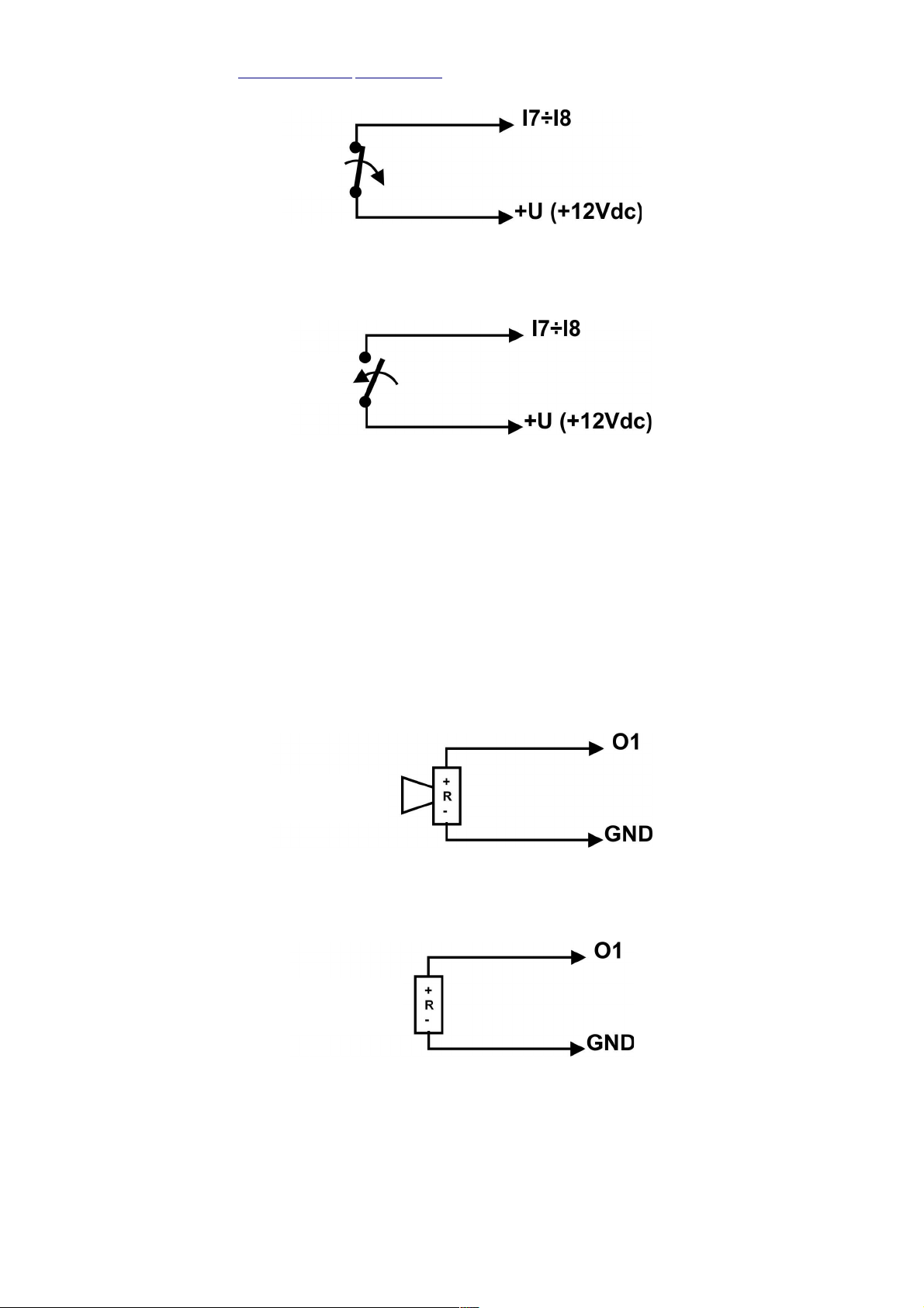
- triggered inputs „+12V” or „GND„ ith configuration NO-NC (I7, I8)
outputs [4]:
- one high current (1A) output and three OC (100mA) outputs
- controlled ith: SMS, CLIP, inputs, module status (alarm, failure etc.)
- programmable mode of operation: MONO- (time) or BISTABLE
- logical functions I/O and O/O: AND, OR, NOR, XOR
communication test function:
- cyclical (every 1-99 hours), according to clock
- triggered by input, external polling
- programmable test type: SMS or CLIP (RING)
module programming:
- local by PC (PARTNER GSM): RS232TTL, USB
- remote by SMS (selected parameters)
- remote by PC: modem do nload (via CSD, required PC+PARTNER GSM+MGSM 5.0)
- firm are update function (FLASH memory)
visual signalization:
- visual signalization of operation and failure status
- visual signalization of outputs status
events memory:
- events registration e.g. alarm arming/disarming
- event date and time (RTC)
- register of 1000 events ith an over rite function
3

2011© Ropam Elektronik [email protected] www.ropam.eu Instalattion and operating manual: MGSM .0/MGSM .0-PS v.1.8S EN
2. PURPOSE
Due extended functionality and diagnostics, modular construction, elastic
configuration and event memory of MGSM 5.0/5.0-PS, it is ideal for:
• intrusion, assault or fire signaling systems:
- as a signaling and controlling channel for control panel
- GSM dialer: SMS, CLIP, SMS+CLIP
• access control systems:
- controlling gate ay: ith SMS(+access code) or CLIP
- GSM dialer: system failure, status etc.
• M2M systems - in automatic control systems for t o ay information exchange:
- GSM transmitter/receiver for technological processes (central heating boiler
and pump installations, PLC controllers, house heating or lighting systems
• burglary alarm (systems):
- control panel for small objects, ith GSM signaling
(e.g. A MGSM 5.0 + PSR-RF or MGSM 5.0-PS unit
3. MODULE DESCRIPTION
3.1 BOARD COMPONENTS AND CONNECTORS DESCRIPTION
4

2011© Ropam Elektronik [email protected] www.ropam.eu Instalattion and operating manual: MGSM .0/MGSM .0-PS v.1.8S EN
COMPONENT /
CONNECTOR DESCRIPTION
+12V-
2Vdc/18Vac
po er supply input:
MGSM 5.0 = 10÷14V/DC
MGSM 5.0-PS= 17÷20V/AC or 20÷30V/DC *
O1 high current output (transistor type , s itching +12V, 1A protection)
AUX po er supply output for auxiliary equipment
( short circuit protected: 300mA, PTC resettable fuse)
O2, O3, O4 lo current OC outputs
(transistor type , s itching GND, not protected against short circuits!))
I1÷I6 module inputs (NO, NC, EOL, 2EOL/NC, 2EOL/NO)
I7, I8 module inputs (NO, NC), trigger by GND or +12V (+U)
GND x4) common terminals (GND, 0V) of inputs and outputs
A, B RS485 bus
TIP, RING
simulated telephone line input (PSTN)
(for connecting a telephone or telephone s itchboard input of dialer's alarm
s itchboard)
X3 not used (for future)
SIMCARD SIM card socket (vertical)
RS 232 TTL RJ12 socket for service computer connection
VSR connector for: voice synthesizer, audio module
EXP communication connector for auxiliary modules e.g. PSR-RF buffered po er supply
module ith built in t o channel radio controller
+BAT-
outputs for battery (BAT, only MGSM 5.0-PS model)
BAT+: red, '+' battery
BAT-: black, '-' battery
JI7, JI8 I7, I8 input polarization configuration jumpers
JRT Jumper: termination resistor − RS−485 line (jumper on = 120 Ohm R)
DO1, DO2, DO3, DO4 GREEN LEDs signaling status of outputs
COMM GREEN LED signaling established communication ith telephone
SEND YELLOW LED signaling SMS sending or dial
(in programming mode – communication ith the computer)
LOG BLUE LED signaling net ork signal level
FAIL RED LED signaling failure
(firm are update in programming mode)
INCOM YELLOW LED signaling SMS receiving or incoming dial
PR connection initiation (programming) via RS232 (TTL) s itch
MODEM GSM industrial telephone SIM300CZ
FME-F FME-F antenna connector (pigtail bulkhead)
3.2 MUDULES DESCRIPTION
3.2.1 VSR-2 : VOICE SYNTHESIZER
This module is used to store and reproduce up to 16 radio announcements (8 x 16s + 8 x
8s). It can be additionally linked ith an audio module for listening-in on objects. MSGM 5.0 enables
independent summing of messages coming from a number of recordings (5), in the event of
violating/sabotaging the input.
3.2.2 VSR-1: VOICE SYNTHETIZER
Module memorizes 20 second voice message. MGSM 5.0 is fully operable ith the VSR-1
synthesizer.
3.2.3 MC1: AUDIO MODULE
5

2011© Ropam Elektronik [email protected] www.ropam.eu Instalattion and operating manual: MGSM .0/MGSM .0-PS v.1.8S EN
The voice module is capable of replaying the object audio during the alarm or after
establishing the voice message. The module should be connected to the S-M input.
3.2.4 PSR: BUFFERED POWER SUPPLY MODULE
The buffered po er supply module 13.8V DC/1.3A ith digital MGSM 5.0 communication.
Operation status and failures diagnostics.
3.2.5 PSR-RF: THE BUFFERED POWER SUPPLY MODULE WITH TWO CHANNEL
RADIO CONTROLLER
The extended PSR version ith built in t o channel radio controller for the remote control of
the MGSM 5.0 (utilizing the control panel function). PSR-RF as an independent device can
functionally replace any t o channel radio link and a buffered 13.8V DC/1.3A po er supply
(together ith the O-R2/O-R3 housings).
4. INSTALLATION
The MGSM 5.0/5.0-PS module should be installed indoors, here air humidity is
normal (RH=90% max. ithout condensation) and temperature in the range of -10°C to
+45°C. When choosing place of installation the follo ing criteria should be taken into
account:
- GSM net ork availability (of the SIM card operator utilized in the module),
- the availability and distance of alarm signal sources and trigger signals (e.g. the control
panel),
- the availability of po er supplies (e.g. buffered po er supply, po er supply module etc.) or
installation possibility of such in vicinity,
- the module requires a po er supply in the follo ing range:
the MGSM 5.0 = 10V-14V/1A min), buffered 13.8V DC power supplies
recommended e.g. recommended dedicated PSR or PSR-RF)
the MGSM 5.0-PS = 17V-20V/30VA, the 17V-20V/AC terminals are used for
connection the secondary winding of mains transformer: O-R2, O-R3 casings)
or DC power supplies recommended 20V-30V/1A min e.g. PSU 24V DC)
- the availability of the premises to third parties and susceptibility to sabotage attempts,
- keeping safe distance from sources of potential interference (e.g. buildings, radio
transmitters, etc. 230V AC main po er supply lines).
The MGSM 5.0/5.0-PS module should be mounted in a dedicated metal housing:
- O-R1, O-R2 or other intended for GSM transmitter or control panel installation:
hen installing the version ithout housing,
- information and communication systems via the DIN 35S bus: hen installing the version
ith housing for the DIN 35S (Z101) bus.
4.1. MODULE COMMISSIONNING PROCEDURE
1. The complete signaling and po er supply iring should be implemented.
2. Mount the housing and insert the iring through the cable glands.
3. Install the SIM card in the module:
Insert the card in the SIMCARD socket in the vertical position, ith the golden contacts of the
SIM card directed to ards the closer edge of the PCB board. The marker (cut-out) of the SIM
card must be directed opposite to the direction of inserting.
6

2011© Ropam Elektronik [email protected] www.ropam.eu Instalattion and operating manual: MGSM .0/MGSM .0-PS v.1.8S EN
4. Install the module:
a) in the O-R1, O-R2 O-R3 housing on the pins included in the kit,
b) in the GSM transmitter housings or control panel housing on the self adhesive pins
supplied ith the module,
c) in the information and communication systems housing using the clip securing the
DIN housing to the assembly bus.
4. Connect the optional additional modules: VSR-2, PSR, PSR-RF
5. Connect the ires to the appropriate module connectors.
6. Connect the external antenna to the FME-F connector.
7. S itch on the module po er supply.
8. Connect the cable bet een the service computer and the RS TTL socket (RS232, USB).
9. Configure the module according to requirements.
10. Perform tests.
11. Disconnect the cable from the RS TTL connector.
Remarks:
•Observe all possible precautionary measures against static discharge to protect
the electronic components.
•Do not switch on the power supply when the external antenna is not connected.
•When installing in O-R2, O-R3 and other dedicated housings, intended for using
with the mains power supply with transformer), do not connect the N “zero”)
cable to the PE grounding clamp of the 230V AC mains power supply. Connecting
the N cable to the PE clamp may damage the electronic components, as GND is
then directly connected to PE! If there is no separate grounding cable provided,
the clamp should be left disconnected.
• In pt. 2.b pins should be inserted in the module PCB board 4 pcs.) Remove the
protective foil from the adhesive layer, place on the inside degreased housing
surface and press lightly.
4.2. CONNECTING THE VOICE SYNTHETIZER OR AUDIO MODULE.
The MGSM 5.0/5.0-PS module has a VSR socket intended for connecting the VSR-2,
ARA and the MC-1 audio or other (e.g. utilized in CCTV) voice synthesizer modules,
provisioned for listening in on the object.
●The voice synthesizer can record and relay a voice command hen an event (alarm) occurs
in the system. Replay is performed automatically after establishing voice communication. The
message is repeated cyclically until the connection is terminated. The voice synthesizer
should be connected directly to the VSR connector and the message recorded after the po er
supply is s itched on (built in microphone).
The message is stored even after the po er supply is disconnected (disconnected
synthesizer).The synthesizer has got a MINIJACK output for listening to the recording.
●Listening in on the object can be accomplished ith the AMR-1 module, hen the alarm is
triggered or hen a voice message is established (connecting ith the module from
7

2011© Ropam Elektronik [email protected] www.ropam.eu Instalattion and operating manual: MGSM .0/MGSM .0-PS v.1.8S EN
authorized lines). To connect the MGSM 3.5/3.5-PS, MGSM 5.0/5.0-PS, VSR-2 and AMR-1
(or other) modules, the 5-pin plug should be used. The connections should be performed, as
in the diagram, using the microphone cable or t isted UTP pair over small distances.
VSR, AUDIO-IN, S-M DESCRIPTION
1GND – 0V, po er supply ground
2AUDIO IN – audio signal input
3SYNTHESIZER TRIGGER - 5V during
the alarm, voice message (period 20s)
4AUDIO OUT – audio signal output
5+ 12V – voice synthesizer or
audiomodule po er supply
4.3. DEVICE CONNECTION TO INPUTS
MGSM can operate ith many types of input polarities. It can operate ith any of the
follo ing:
- detectors ith outputs: NC (normally closed), NO (normally open),
- alarm outputs: relay (RELAY zero potential contacts)
- open collector (OC, BELL – negative po er supply controlled)
- high current (positive po er supply controlled +12V)
TYPE
POLARITY
INPUTS
NC NO EOL 2EOL/NC 2EOL/NO
I1÷I6 √ √ √ √ √
I7, I8 √
GND or
+12V)
√
GND or
+12V)
XXX
√ - Ix input operates with a given type of polarity
X - Ix input does not operate with a given type of polarity
Polarity type: NC.
8
NC
contact

2011© Ropam Elektronik [email protected] www.ropam.eu Instalattion and operating manual: MGSM .0/MGSM .0-PS v.1.8S EN
Polarity type: NO.
Polarity type: EOL with a TAMPER contact).
Polarity type: 2EOL/NC with a TAMPER contact).
Polarity type: 2EOL/NO with a TAMPER contact).
9
NO
contact
NC
contact
NC
contact-
TAMPER
NC
contact
NO
contact
NC
contact-
TAMPER
NC
contact-
TAMPER

2011© Ropam Elektronik [email protected] www.ropam.eu Instalattion and operating manual: MGSM .0/MGSM .0-PS v.1.8S EN
Polarity type only I7, I8): NO
trigger by +12V,
(the jumper JI7 or JI8 isn't installed)
Polarity type only I7, I8): NC
trigger by +12V,
(the jumper JI7 or JI8 isn't installed)
4.4. DEVICE CONNECTION TO OUTPUTS.
The MGSM 5.0/5.0-PS module has got outputs for control and signaling the operation status.
- O1: in the active state e can connect (NO) or disconnect (NC) +12V po er supply (transistor
output controlling the po er supply “+” ith an electronic fuse triggered at 1A)
Output O1: connecting a siren 12VDC/1A max.
acoustical and/or optical signaling ).
Output O1: connecting a load 12VDC/1A max.
10
NC
contact
NO
contact
SIREN
12V DC
LOAD
12V DC
P=12W max.

2011© Ropam Elektronik [email protected] www.ropam.eu Instalattion and operating manual: MGSM .0/MGSM .0-PS v.1.8S EN
Output O1: connecting a relay 12VDC coil).
- O2, O3, O4 in the active state can connect (NO) or disconnect (NC) the 0V po er supply (GND),
the open collector (OC) transistor outputs, control the ground of the po er supply, 100mA max.
Output O2, O3, O4: connecting a siren 12VDC/100mA max.
acoustical and/or optical signaling ).
Output O2, O3, O4: connecting a relay 12VDC coil)
Output O2, O3, O4: connecting a LED +12V=AUX)
- AUX po er supply output for auxiliary equipment: 12V, 300mA max. The output has short circuit
protected by PTC fuse (resettable). If the AUX output is loaded by current exceeding 300mA-600 mA the
automatic isolation of output voltage. hen the load shall be disconnected from the AUX output for about 1 min.
11
RELAY
12V DC coil)
SIREN
12V DC
100mA max.
RELAY
12V DC coil)
LED

2011© Ropam Elektronik [email protected] www.ropam.eu Instalattion and operating manual: MGSM .0/MGSM .0-PS v.1.8S EN
–Output AUX: connecting a load 12V DC e.g. detectors, code lock, LED)
Remarks:
●The maximum 02, 03, 04 outputs current is 100 mA R min. = 140 Ohm at
13.8V DC).
4.5. DEVICE CONNECTION TO OUTPUT TIP-RING
- TIP, RING simulated telephone line input (PSTN)
(for connecting a telephone or telephone s itchboard input of dialer's alarm s itchboard)
Remarks:
•Connecting the telephone circuit directly to PSTN analog or digital network)
will cause damage to the equipment and electric shock.
5. PROGRAM „PARTNER GSM v3.5”
The PARTNER GSM v3.5) software is intended for operation on PC class computers
running under the WINDOWS 9X/Me/2000/XP/VISTA operating system. Communication
between PARTNER GSM and MGSM 5.0/5.0-PS is accomplished via: the RS232 port or the
USB 1.1, 2.0) port utilizing communication cables with a built in RS-232-RS232-TTL or a
USB-RS232-TTL converter. Dedicated RS232-MGSM or USB-MGSM cables are
recommended.
5.1. SOFTWARE DESCRIPTION
The soft are supports a graphical and text menu. Forbidden operations or functions for a
given type of device are displayed as inactive (grey icons and text). Communication functions are
active only after the correct configuration of the RS 232 port (COM) and initiation of communication
ith the module.
12
LOAD 12V DC
P=3,6W max.
TELEPHONE,
TELEPHONE
SWITCHBOARD,
ALARM DIALER'S

2011© Ropam Elektronik [email protected] www.ropam.eu Instalattion and operating manual: MGSM .0/MGSM .0-PS v.1.8S EN
13
FILE
> NEW - configuring the MGSM xxx module in the offline mode
> READ – opening the configuration file from the computer disc (*rpm)
> WRITE – riting the present configuration to the computer disc
> EXIT – exiting the PARTNER GSM soft are
MODULE
> OPEN/CLOSE COM PORT – open or close the RS 232 port marked in the COM bookmark
> READ F4 – read the module configuration (communication active)
> WRITE F5 – rite configuration to module (communication active)
> IN-4 INPUT MODULE ADD/DELETE –adds /deletes the module IN-4 configuration bookmark in
the off-line mode
> POWER SUPPLY PSR-RF ADD/REMOVE - adds/removes the PSR/PSR-RF po er supply
module configuration bookmark in off-line mode
HELP
> HELP – open help file
> HOME PAGE – open page .ropam.eu
READ – open file ith configuration from computer HDD, CD etc. (*rpm file)
WRITE – rite current configuration to computer HDD (local)
OPEN/CLOSE COM PORT – RS 232 port marked in the COM bookmark
- COM CLOSED (not active), - COM OPEN (active)
READ F4 - read module configuration (communication active)
- communication active (red color)
- communication not active (grey color)
WRITE F5 - rite module configuration (communication active)
- communication active (red color)
- communication not active (grey color)
HELP – open help file
EXIT – exit PARTNER GSM soft are
PROGRAMMING/FLASHING PROGRESS MARKER
ACTIVE COMMUNNICATION MARKER
CHOICE OF COM PORT NUMBER RS 232)
MODEM CONNECTION CSD) – start/stop remote configuration
via modem connection.
LANGUAGE
> language selection: e.g. English

2011© Ropam Elektronik [email protected] www.ropam.eu Instalattion and operating manual: MGSM .0/MGSM .0-PS v.1.8S EN
5.2. “PARTNER GSM” COMMUNNICATION WITH THE MGSM 5.0/5.0-PS
5.2.2 LOCAL CONFIGURATION VIA RS 232TTL PC: RS232, USB)
The MGSM 5.0/5.0-PS module is configured via the RS 232 TTL interface. To enter the
configuration process, the follo ing actions should be performed:
1. S itch off the module po er supply.
2. Connect the communication cable to the RS 232 connector on the module board.
3. Connect the cable to the service computer port (options: RS 232 or USB).
4. Start the service computer and the PARTNER GSM soft are.
5. S itch on the module po er supply.
6. In the PARTNER GSM soft are:
6a.Enter the PASSWORD in COMMUNICATION OPTIONS
factory password: 123B);
6b.Select the COM port number and open it; the state of ”waiting to be connected
with the module” is signalized by a message in the footnote: WAITING FOR
MODULE RESPONSE or
6c. The ”AUTO-DETECT COM” option must be marked.
Open the COM port and start procedure no.7 press the PR switch) the PARTNER
GSM starting procedure : 'AUTOSCAN' active COM ports two rounds).
7. Press the PR s itch (ca. 1 second), yello SEND diode flashes.
8. The module communication should be initiated – the communication options should become
visible. Furthermore, the functioning communication is signalzied by the flashing „light” next
to the port number and the COMMUNICATION ESTABLISHED message is
displayed in the PARTNER GSM soft are footnote, together ith the device type, modem and
module firm are version number.
9. Configure the module, perform (ON-LINE) tests etc.
During the read/ rite etc. this is signalled ith an appropriate message in the program
footnote by a fractional indicator.
10. To end the communication, press the PR s itch (the yello SEND LED ill flash 4-5 times).
11. Disconnect the cable from the RS 232TTL connector.
12. Perform tests and user training.
5.2.2 REMOTE CONFIGURATION VIA MODEM CONNECTION CSD)
In the local connection mode for MGSM 5.0/5.0-PS module (via RS232 – see: Local Configuration),
it is possible to establish a modem connection ith another module. In order to establish a
modem connection, follow these steps:
1. Enter the PASSWORD in the COMMUNICATION OPTIONS factory password: 123B)
The password must be identical to the password in the MGSM 5.0 /5.0-PS remote
module and the MODEM ACCESS option must be programmed.
2. Click the MODEM CONNECTION icon.
3. The correct list of modem connection sessions ill be confirmed by an appropriate message.
14

2011© Ropam Elektronik [email protected] www.ropam.eu Instalattion and operating manual: MGSM .0/MGSM .0-PS v.1.8S EN
4. Incorrect connection, communication pass ord discrepancy, lack of modem access ill be
confirmed by an appropriate message.
5. While staying in a modem connection, the follo ing functions are available:
6. SAVE CONFIGURATION
READ CONFIGURATION
EVENT MEMORY READOUT
7. ONLINE MODE – MONITORING OF STATUS AND OUTPUT CONTROL (about 1-2s delay).
8. Press the MODEM CONNECTION icon to end communication.
REMARKS:
In the event that the modem connection is interrupted while changing the
configuration the module will be automatically restored based on the backup copy.
The configuration back-up copy is made automatically after each correct
configuration change (confirmation of the CRC checksum).
5.3. COMMUNNICATION CABLES: RS232-MGSM, USB-MGSM.
The connection diagram of the RS232-MGSM or the USB-MGSM cable to the MGSM 5.0/5.0-
PS module. The SAT_TTL-MGSM cross-over is delivered together ith the cable. After disconnecting
it, the cable can be used for programming other devices ith RS232TTL interface (equivalent to RS-
CA5/CA6). The RS232-MGSM cable should be used to connect ith the PLC controller if the SMS
received from the RS232 sending function is utilized.
15

2011© Ropam Elektronik [email protected] www.ropam.eu Instalattion and operating manual: MGSM .0/MGSM .0-PS v.1.8S EN
6. FUNCTIONAL DESCRIPTION
Functions descriptions and configuration method are explained in the windows and
with messages in the PARTNER GSM software.
Remarks:
•The constantly updated soft are and ne ly implemented ne functions can be
do nloaded by using the PARTNER GSM soft are. The most recent version of the
soft are can be do nloaded from .ropam.eu or directly in PARTNER GSM
soft are by using the UPDATE option.
6.1. SIM CARD PIN accessible in all bookmarks)
The SIM card PIN installed in the telephone
should be entered in this field. When using a card
ithout a PIN code, the ”PIN code not required” option should be marked.
Remarks:
•the default setting is: „PIN code not required”. The SIM card can be installed
and the module commissioned without concern about blocking the SIM card by
entering the wrong PIN from module.
•function „ PIN code not required “ is not disable PIN code request for SIM card.
If you use this function, you must use a mobile phone to change security
option on SIM card.
•6.2. NUMBERS
Telephone numbers, SMS center numbers, module SIM card PIN number and an installation
note can be entered in this bookmark.
16

2011© Ropam Elektronik [email protected] www.ropam.eu Instalattion and operating manual: MGSM .0/MGSM .0-PS v.1.8S EN
Remarks:
module telephone number and the note are not entered into the module memory
but into a file on the local PC computer.
6.2.1 PHONE NUMBERS
The MGSM 5.0/5.0-PS module can signal four telephone numbers. The numbers should be
entered in the international format.
e.g. mobile number: +48555666777, fixed phone number: +48125556677
6.2.2 SMS CENTER
The SMS center number should be chosen from the operators list bookmark (the number ill
be displayed automatically) or the field edited manually. The number should be entered using the
international format.
Remarks:
•The SMS CENTER is the SMS center number of the module SIM card telephone
GSM operator.
•when number is wrong or missing, SMS sending will be blocked!
6.2.3 OBJECT TELEPHONE NUMBER
This is the number of the SIM card in the module telephone. This field is not recorded in the
module, but only serves as an information note. The number is recorded in the configuration file on
the service computer. (see. 5.2.2 REMOTE CONFIGURATION VIA MODEM CONNECTION)
6.2.4 COMMUNICATION OPTIONS
PASSWORD – it must be composed of four characters. The combination of digits and letters is
permitted. (Characters in the pass ord are case-sensitive).
The pass ord is used to secure the communication ith a PC: via local and modem connection.
MODEM ACCESS – marking this option enables establishing a modem connection ith a
remote PC+MGSM 5.0.
6.2.5 NOTES
This field is not recorded in the module, but only serves as an information note. It is recorded
only in the configuration file on the service computer.
17

2011© Ropam Elektronik [email protected] www.ropam.eu Instalattion and operating manual: MGSM .0/MGSM .0-PS v.1.8S EN
6.3 INPUTS
Input configuration, module reactions to violations and restores to a normal state,
can be set in this bookmark. The module has got eight inputs on the main board.
6.3.1 MGSM INPUTS
●POLARITY:
The inputs of MGSM 5.0/5.0-PS can operate ith many types of polarities:
I1-I6: NO, NC, EOL, 2EOL/NO, 2EOL/NC, OFF
I7-I8: NO, NC trigger by (0V ) or (+VDC)
■NO – denotes the GND level triggered signal (0V DC) NORMALLY OPEN state input.
The I7, I8 inputs can be triggered by GND (0V DC) or “plus” (+VDC ), depending on
the JI7 and JI8 settings.
The input in the NORMALLY OPEN state is triggered by
the GND (0V) signal.
The input in the NORMALLY OPEN state is triggered by
the “plus” (+U) signal.
JI7 is by default (ON)/ NO in the
soft are
I7 in the NORMALLY OPEN state, is triggered
by the (short circuit) GND signal.
JI7 is (OFF)/ NO in the soft are I7 in the NORMALLY OPEN state, is triggered
by disconnecting “plus” signal
18
GND
+12V
+

2011© Ropam Elektronik [email protected] www.ropam.eu Instalattion and operating manual: MGSM .0/MGSM .0-PS v.1.8S EN
JI8 is by default (ON)/ NO in the
soft are
I8 in the NORMALLY OPEN state, is triggered
by the (short circuit) GND signal.
JI8 is (OFF)/ NO in the soft are I8 in the NORMALLY OPEN state, is triggered
by the disconnecting“plus” signal
●NC – denotes the input NORMALLY CLOSED state , triggered by disconnecting „mass”
(0V DC).
The I7, I8 inputs can be triggered by GND (0V DC) or “plus” (+VDC ), depending on
the JI7 and JI8 settings.
Input in the NORMALLY CLOSED state, triggered by
disconnecting “mass”.
Input in the NORMALLY CLOSED state, triggered by
the (short circuit) “plus” (+U) signal.
JI7 is by default (ON)/ NC in the
soft are
I7 in the NORMALLY CLOSED state, triggered
by disconnecting “mass”.
JI7 is (OFF)/ NC in the soft are I7 in the NORMALLY CLOSED state, is
triggered by the (short circuit) “plus” signal.
JI8 is by default (ON)/ NC in the
soft are
I7 in the NORMALLY CLOSED state, triggered
by disconnecting “mass”.
JI8 is (OFF)/ NC in the soft are I7 in the NORMALLY CLOSED state, is
triggered by the (short circuit) “plus” signal.
●EOL – denotes the input in the PARAMETRIC state (one parametric resistor), triggered
by disconnecting the parametric resistor 2.2 kΏ which must be connected
between the input and the system mass.
The input in the PARAMETRIC state is triggered by disconnecting the
parametric 2.2 kΏ resistor.
●2EOL/NO – denotes an input in the configuration: t o-parametric, NORMALLY OPEN
sensor; the sensor’s circuit is closed ith t o 1.1 kΩ resistors. 2 EOL inputs enable
the control panel a simultaneous monitoring of sensor status and its sabotage contact.
●2EOL/NC – denotes an input in the configuration: t o-parametric, NORMALLY
CLOSED sensor; the sensor’s circuit is closed ith t o 1.1 kΩ resistors. 2 EOL inputs
enable the control panel a simultaneous monitoring of sensor status and its sabotage
contact.
●OFF – s itches the input off independently of other input settings
Remarks:
•inputs I1-I8 can be triggered directly by low current OC outputs
•inputs: I7, I8 can be triggered by positive high current outputs
19
GND
GND
2,2k
+12V
+

2011© Ropam Elektronik [email protected] www.ropam.eu Instalattion and operating manual: MGSM .0/MGSM .0-PS v.1.8S EN
●TYPE:
●INFO- data on input does not trigger the alarm function, but initiates SMS sending
and the call queuing process.
●24h- module enters the alarm state, sends SMS messages and makes calls,
independently of hether it is in the standby mode or not.
●INSTANT - the line initiates the alarm, SMS messages and calling when the
module is in the armed mode.
●ARM/DISARM- s itching ARM/DISARM line, violation s itches standby mode on, end
of violation s itches it off. Line can operate also in the pulse mode (“pulsed line”
option on) as follo s: first violation arms the module, the second violation disarms it
and so on alternately. The ARM/DISARM line can s itch the SMS and voice signaling
off hen the option SIGNALLING OFF is marked (signaling ill be terminated hen the
module is disarmed, independently of the signaling function progress!).
•DELAYED - line triggers the alarm, SMS messaging and calling after time for entry
has elapsed, only hen the module is disarmed. The time for entry can be set in the
OPTIONS bookmark.
INTERIOR DELAYED - the line triggers the alarm, text messaging (SMS) and calling
after the time for entry has expired and the armed mode has not been s itched off, if
the DELAYED entry has been violated in the first place. Other ise, it operates as a
NORMAL entry.
The time for entry can be set in the OPTIONS tab.
•COUNTING – violation of this type of line ill result in the incrementation of the
violation counter and hen it reaches it’s value, it initiates the alarm procedures. The
line is active in the module standby mode (exactly like the NORMAL) and the violation
counter is reset after a certain time measured from the last violation.
e.g. for values as in the diagram, to initiate the alarm from the counter line, it should be
violated 2 times at intervals not longer than 60 seconds.
•REACTION TIME
This parameter determines the time in ms (1s=1000ms), during hich the input must be
violated to detect it’s change of state. For each input, the reaction time can be set
independently (500 ms by default)
•FLASH
Determines hether the sent SMS message is to be displayed directly on the telephone
screen (flash), or hether it should be read from the “received mail” box. Selecting the
option configures the input SMS type for the “violation” and “entry restore”
Remarks:
●it should be remembered that FLASH type SMS messages can be very easily
overlooked, because they are not recorded in the telephone they disappear
from the telephone screen when there is an incoming call)
●the FLASH option may not be available while sending SMS messages to a different
operator than the one whose card is in the module this does not depend on the
settings but it is a result of limitations imposed by operators!).
●BLOCK FOR
The time of blocking the input (response) after the first violation. This option is active for the
follo ing TYPES of entry: INFO, NORMAL, DELAYED, INTERNAL DELAYED, 24H. The time of
blocking can be set separately for each entry (the default setting is 0s). Min/max time =
1/360min (this option is used for limiting the number of messages and hen using the MGSM
5.0/5.0-PS as an alarm control panel; it enables actual control of the armed mode through
the SMS messages).
•VSR
This column enables configuring the content of voice messages, in cooperation ith the VSR-
2 Voice Synthesizer.
20
This manual suits for next models
1
Table of contents
Other Ropam elektronik Control Unit manuals
Popular Control Unit manuals by other brands

Fibocom
Fibocom G510 Hardware user manual

PHOENIX DIGITAL
PHOENIX DIGITAL OCM-DPR-1 Installation and user manual

Victaulic
Victaulic FireLock NXT 769N Series Installation, Maintenance, and Testing Manual

Pepperl+Fuchs
Pepperl+Fuchs VAA-2E-G4-SN instruction manual

Quectel
Quectel EM160R-GL Hardware design

bonitron
bonitron M3345D Customer Reference Manual