Customer Services, Roper Rhodes Ltd, Brassmill Lane Trading
Estate, Bath, BA1 3JF
Tel:01225 303 900 | Fax: 01225 448 877
Please retain for future reference
Cirrus Wall Mounted Unit
Installation & aftercare instructions
Please retain for future reference
Replacement Components
Should you require any replacement components for this product please contact Roper Rhodes using the contact details below.
RR-CIR900 REV : 02.03.15RR-CIR900 REV : 02.03.15
The isocast basin is made of a non-porous material and as such it can be wiped clean with a damp cloth or sponge using mild detergents or soapy
water. DO NOT use abrasive cleaning solutions. Where possible avoid sliding hard or sharp objects on the surface to prevent scratches. Strong acids
such as those found in drain cleaners, toilet cleaners, paint removers and cleaners containing methylene chloride or acetone (nail polish remover)
should be used very cautiously around the isocast material. Should this product come in contact with the surface, quickly flush the surface with plenty of
soapy water. Any residue and spills from, shampoo, toothpaste, mouthwash, etc. should be cleaned immediately with soapy water to ensure no damage
occurs.
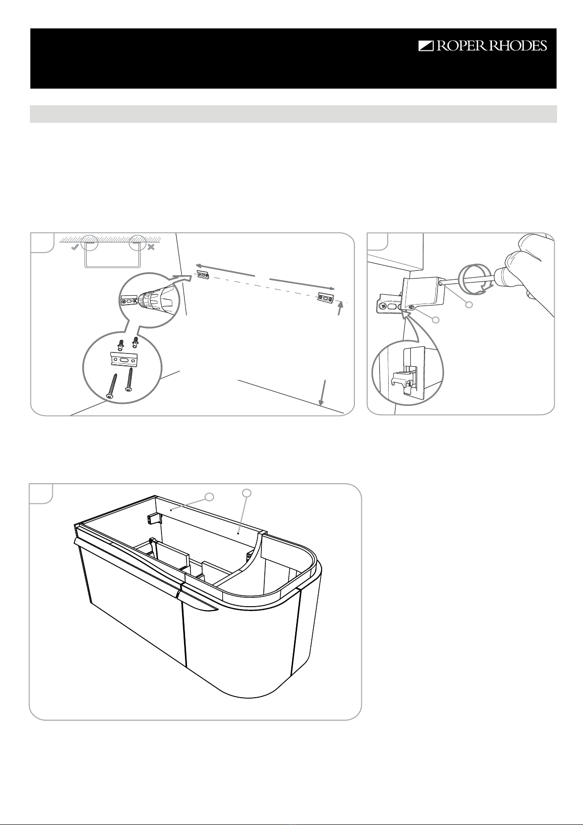
Fitting the Basin
Once the basin has been plumbed in, finish by securing to the furniture unit using a silicone sealant (not supplied).
Isocast Basin Maintenance Instructions
Furniture Aftercare Instructions
As with all wooden furniture, this product should be treated with care.
We recommend...
Wipe away any water splashes or condensation after use. Excessive exposure to water will deteriorate the furniture.
All bathrooms should be well ventilated with a suitable extractor fan.
Clean with a soft damp cloth only.
Use a wax free polish if one must be used.
For removal of lime scale deposits use a suitable proprietary cleaner. If necessary test on an incspicuous area first
Do not scrub or scour
Do not use abrasive cleaning
agents
Please DO NOT...
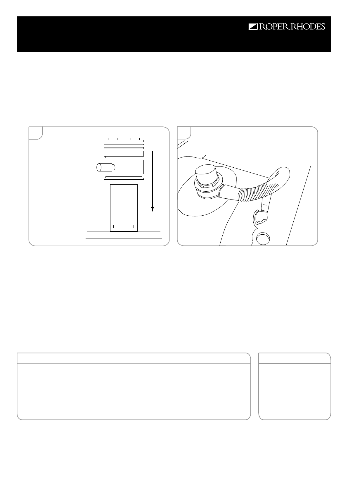
The basin is supplied with an overflow kits which contains: 1pc plastic corrugated pipe, 1pc thin rubber stepped washer, 1pc thick rubber stepped
washer, overflow attachment. These should be used with a slotted waste to allow the overflow to function correctly.
The waste should be placed through the basin hole and then the components should be slid down over this as in figure 1 below (items supplied with
waste may vary). The waste should be rotated such that the slot is in line with the inlet on the overflow attachment. The waste nut should be tightened
to fully compress all of the fittings in place. Finally the plastic tube should be attached to the basin and overflow attachment as shown in figure 2. A
sealant should be used at both ends and anywhere deemed appropriate by the installater. This should be tested for water-tightness prior to domestic
use.
basin
1. waste (slotted)
3. overflow attachment
7. waste nut
6. waste metal ring
5. waste rubber washer
2. overflow thin rubber washer
4. overflow thick rubber washer
slot
inlet
15 16