Roper Whitney 10M14-G User manual

ROPER WHITNEYROPER WHITNEY
of ROCKFORD, Inc.of ROCKFORD, Inc.
10M14-G10M14-G
10 FOOT 14 Ga SHEAR10 FOOT 14 Ga SHEAR
OPERATIONS MANUALOPERATIONS MANUAL
ROPER WHITNEY of ROCKFORD, Inc.
2833 Huffman Blvd.
Rockford, IL 61103
(815) 962-3011
FAX: (815) 962-2227
www.roperwhitney.com
LAST MODIFIED JULY, 1997

TABLE OF CONTENTS
TOPIC PAGE
10M14 Mechanical Shear . . . . . . . . . . . . . . . . . . . . . . . . . . . . . . . . . . . . . . . . . . . . . . . . . . . . . . . . . . 1
Specifications . . . . . . . . . . . . . . . . . . . . . . . . . . . . . . . .. . . . . . . . . . . . . . . . . . . . . . . . . . . . . . . . . . . . 2
Physical machine dims . . . . . . . . . . . . . . . . . . . . . . . . . . . . . . . . . . . . . . . . . . . . . . . . . . . . . . . . . . . . . 4
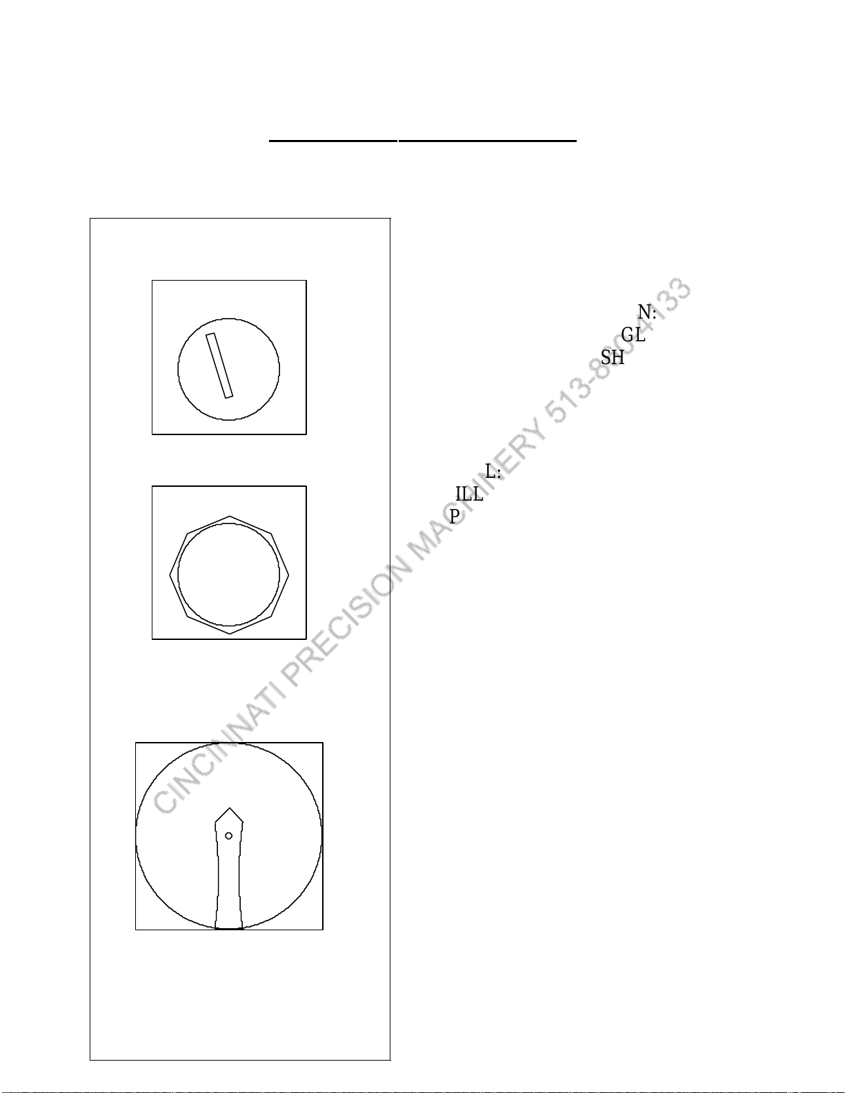
Operator's Control Panel Layout . . . . . . . . . . . . . . . . . . . . . . . . . . . . . . . . . . . . . . . . . . . . . . . . . . . . . 5
Electrical Panel Layout . . . . . . . . . . . . . . . . . . . . . . . . . .... . . . . . . . . . . . . . . . . . . . . . . . . . . . . . . . . . 6
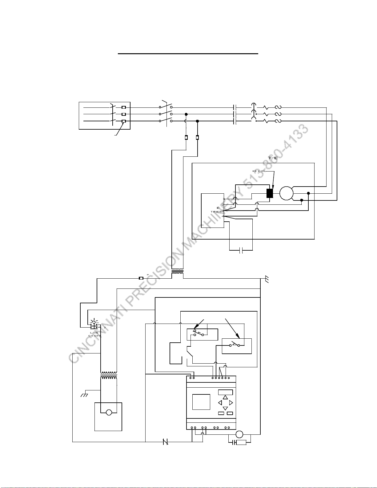
Electrical Wiring Daigram . . . . . . . . . . . . . . . . . . . . . . . .. . . . . . . . . . . . . . . . . . . . . . . . . . . . . . . . . . 7
Safety Instructions . . . . . . . . . . . . . . . . . . . . . . . . . . . . . . . . . . . . . . . . . . . . . . . . . . . . . . . . . . . . . . . 8
Installation Instructions . . . . . . . . . . . . . . . . . . . . . . . . . . . . . . . . . . . . . . . . . . . . . . . . . . . . . . . . . . . . 10
Leveling of machine . . . . . . . . . . . . . . . . . . . . . . . . . . . . . . . . . . . . . . . . . . . . . . . . . . . . . . . . . . . . . . . 10
Cleaning of machine . . . . . . . . . . . . . . . . . . . . . . . . . . . . . . . . . . . . . . . . . . . . . . . . . . . . . . . . . . . . . . 10
Electrical Connections . . . . . . . . . . . . . . . . . . . . . . . . . . . . . .. . . . . . . . . . . . . . . . . . . . . . . . . . . . . . . 11
Maintenance . . . . . . . . . . . . . . . . . . . . . . . . . . . . . . . . . . . . . . . . . . . . . . . . . . . . . . . . . . . . . . . . . . 11
Operating Instructions . . . . . . . . . . . . . . . . . . . . . . . . . . . . . . . . . . . . . . . . . . . . . . . . . . . . . . . . . . . . 12
Blade Repositioning/Replacement . . . . . . . . . . . . . . . . . . . . . . . . . . . . . . . . . . . . . . . . . . . . . . . . . . 14
Blade Clearance Adjustment . . . . . . . . . . . . . . . . . . . . . . . . . . . . . . . . . . . . . . . . . . . . . . . . . . . . . . . 17
Side Extension Arms . . . . . . . . . . . . . . . . . . . . . . . . . . . . . . . . . . . . . . . . . . . . . . . . . . . . . . . . . . . . . 20
Front Arms . . . . . . . . . . . . . . . . . . . . . . . . . . . . . . . . . . . . . . . . . . . . . . . . . . . . . . . . . . . . . . . . . . . . . 20
Light Beam Assembly . . . . . . . . . . . . . . . . . . . . . . . . . . . . . . . . . . . . . . . . . . . . . . . . . . . . . . . . . . . . 21
Rear-operated Backgague . . . . . . . . . . . . . . . . . . . . . . . . . . . . . . . . . . . . . . . . . . . . . . . . . . . . . . . . . 22
Front-operated Backgage . . . . . . . . . . . . . . . . . . . . . . . . . . . . . . . . . . . . . . . . . . . . . . . . . . . . . . . . . . 22
Front Material Return . . . . . . . . . . . . . . . . . . . . . . . . . . . . . . . . . . . . . . . . . . . . . . . . . . . . . . . . . . . . 23
DRO Specifications . . . . . . . . . . . . . . . . . . . . . . . . . . . . . . . . . . . . . . . . . . . . . . . . . . . . . . . . . . . . . . 25
Using the DRO . . . . . . . . . . . . . . . . . . . . . . . . . . . . . . . . . . . . . . . . . . . . . . . . . . . . . . . . . . . . . . . . . 26
Programming the DRO . . . . . . . . . . . . . . . . . . . . . . . . . . . . . . . . . . . . . . . . . . . . . . . . . . . . . . . . . . . 28
DRO Parameter Values . . . . . . . . . . . . . . . . . . . . . . . . . . . . . . . . . . . . . . . . . . . . . . . . . . . . . . . . . . 29
NC Specifications . . . . . . . . . . . . . . . . . . . . . . . . . . . . . . . . . . . . . . . . . . . . . . . . . . . . . . . . . . . . . . 30
Programming the NC. . . . . . . . . . . . . . . . . . . . . . . . . . . . . . . . . . . . . . . . . . . . . . . . . . . . . . . . . . . . 31
Using the NC . . . . . . . . . . . . . . . . . . . . . . . . . . . . . . . . . . . . . . . . . . . . . . . . . . . . . . . . . . . . . . . . . . 32
NC Parameter Values . . . . . . . . . . . . . . . . . . . . . . . . . . . . . . . . . . . . . . . . . . . . . . . . . . . . . . . . . . . . 34

10M14-G MECHANICAL SHEAR
The ROPER WHITNEY 10M14-G mechanical shear is designed and tested to handle 14
gauge mild steel in 10-foot widths. The power drive is through a mechanical linkage with a 5HP
motor brake and gear reducer. The cutting action can be set for single cycle or continuous cycle
by means of a front mounted switch on the control box. All cutting is operator controlled by
use of a foot-switch. The motor only operates when the foot-switch is actuated, thus reducing
continuous electrical power drain in comparison to an "always on" running motor. The
10M14-G shear runs very quiet as a result of this motor actuation system. The shear blades are
two edged, and upper and lower blades are interchangeable. The shear comes standard with a
manual style backgauge that is offered either as a front or rear operated type gauging system.
Several optional features that are available include:
1.) full-length light beam
2.) front extension arms with drop stops
3.) front gauge bar to fit onto the front extension arms
4.) side squaring extension gauges in four foot increments up to 12-feet,
with optional flip-type stops
5.) material support and cut-off return mechanism to the front of the shear
6.) DRO (digital read-out) powered backgauge
7.) NC (numerical controlled) programmable powered backgauge
The 10M14-G shear is ready for use upon uncrating -- no adjustments are required. All
load bearings are steel-backed, lead impregnated, and self lubricating to provide rigid structural
support, low maintenance and a long life. Overall the shear construction is of state-of-the-art
heavy plate weldments that are machined with precision requirements to eliminate any need for
adjustment upon its initial set-up and use. Blade clearance is factory set and adjustment, through
the use of adjustment screws, is provided in the case of blade sharpening or blade replacement.
The following diagram shows the mechanical linkage as driven by the motor/brake gearbox:

10M14-G SPECIFICATIONS
Figure 1 (page 5) : Overall machine and floor mounting dimensions
Figure 2 (page 6) : Control panel with the location of the "ON/OFF" safety
disconnect switch, the "PULL ON/PUSH OFF" power
button, and the "CONTINUOUS CYCLE/SINGLE
CYCLE/JOG" selector switch
Figure 3a (page 7) : Electrical panel layout
Figure 3b (page 8) : Electrical wiring diagram
The following are the specifications:
1. Capacity 14 Ga. mild steel
18 Ga. stainless steel (*)
2. Shear width 0-121.25 inches
3. Shear depth 0-24 inches
4. Table depth 15 inches
5. Motor HP 5 HP at 1700 RPM
6. Cycle rate 32 stroke per minute
7. Standard voltages 208/230/460 VAC, 3 PHASE, 60 HZ
8. Approximate weight 5500 lb.
* Roper Whitney of Rockford, Inc. recommends the use of high carbon/high
chrome blades for shearing stainless steel in production quantities. Note, that these
high carbon/high chrome blades are standard on all 10M14 shears.
For more information contact the factory at (815) 962-3011.
2

3

10M14-G PHYSICAL DIMENSIONS
Figure 1
4
LIFTING EYE
25.75131
129
30
64
141
46
14.38
31.75
(4) 3/4" HOLES

OPERATOR'S CONTROL PANEL
Figure 2
MODE OF OPERATION:
CONTINUOUS, SINGLE,
OR JOG ACTION SHEARING
PULL: TURN ON MACHINE
(ILLUMINATED RED WHEN ON)
PUSH: TURN OFF MACHINE
PUSH: EMERGENCY STOP
3-PHASE ELECTRICAL
POWER DISCONNECT SWITCH
5
PUSH TO STOP
PULL TO START
ON
OFF
CONT JOG
SINGLE

ELECTRICAL PANEL LAYOUT
Figure 3a
6
4
L1
L2
L3
TO GEAR/BRAKE MOTOR
22 17
2
TO LIGHT BEAM
TO LIGHT BEAM
TO FOOTSWITCH
TO FOOTSWITCH
TO LIMIT SWITCH
TO LIMIT SWITCH
ON-PULL
OFF-PUSH
ILLUMINATED
4
2
1
2019
TO BRAKE RECTIFIER
TO FOOT SWITCH
6 7 18
4
1876 1920172
PUSHBUTTON
1
L3L2L1
8
5
9
7
2
DISCONNECT
ROTATARY
MAINPOWER
(230V/3PH/60HZ)
GND
2
GND
GND
6
9
11
10
SINGLE CYCLE
CONT CYCLE
SWITCH
SELECTOR
GND
9695
16
14.5
18
CL04
T3
G.E. CL04A310MJ
CONTACTOR
G.E. RT1S
20
19
8
52
JOG CYCLE
T2T1
M
M-O
A-O
A
RESET
TEST
A1 A2
14NO
1L1 3L2 5L3 13NO
6T34T22T1
NCNO
97 98
SURGE SUPRESSOR
G.E. BSLR2R
10
11
H2
150VA
#B150MBT713RK
24/120 VAC OUT
208/230/460 VAC IN
TRANSFORMER
MICRON CONTROL
H1
L1
FU4, 6 AMP
FU3, 2 AMP
L2
H3H4
X2X3 XFX1
FU2,2AMP
FU1,2AMP
18
17
1
18
18
18
1
1
4
44
120V
24V
230V
ESC OK
230/240V
AC115/120V Input 6 x AC
NL1 I1I2I3I4I5I6
Q4Q3Q2Q1
Output 4xRelay/8A
LOGO! 230R
SIEMENS

ELECTRICAL WIRING DIAGRAM
Figure 3b
7
QTY (3)
FUSE, 30 AMP
SAFETY SWITCH 230/3/60, 30 AMP, NEMA 1
REMOTE MOUNT EQUIPMENT ROTATARY
2 AMP
FU1
OL
120VAC
230/3/60 VAC
MS
DISCONNECT
1 4
REMOTE MOUNT EQUIPMENT
M
T1
T2
T3
1
2
3
4
5
MS
BGE
RECTIFIER
RED
WHITE
BLUE
BRAKE COIL
1920
13.6 AMPS
5.O HP
2 AMP
FU2
4
PUSH OFF
PULL ON
1817
LIGHT
OPTIONAL
EQUIPMENT
W
120VAC
SINGLE
11
A2A1
ESC OK
230/240V
AC115/120V Input 6 x AC
NL1 I1 I2 I3 I4 I5 I6
Q4Q3Q2Q1
Output 4xRelay/8A
LOGO! 230R
SIEMENS
RC
REMOTE MOUNT EQUIPMENT
24VAC
120VAC
REMOTE MOUNT EQUIPMENT MS
OL
LIMIT SWITCH
FOOT SWITCH
8
5
67
JOG
CONT
10 9
4
2 AMP
FU3
2
2
CUSTOMER SUPPLIED

ROPER WHITNEY of ROCKFORD, INC.
SAFETY RULES --- 10M14-G SHEAR
1. WARNING:
Electrical Danger -- Misuse or improper installation of machinery connected to a
source of electricity may result in accidental shock that could cause injury or death.
Installation must conform to National Electric Code (Article 250 - Grounding, etc.)
Electrical connections must be made by a trained and qualified electrician.
Electrical characteristics shown on motor plate and control panel must match the
power source; and all electrically powered equipment must be grounded.
2. WARNING:
Mechanical Danger -- Do no adjust the holddown; it is factory set for 3/16 inch
gap and acts as the hand-guard. Do not exceed the work-piece material capacity --
otherwise serious damage will occur with your shear.
3. Machine to be operated by authorized personnel who have been trained by their
supervisor with the working and safety features of the machine, and by reading and
understanding the Operator's Manual.
4. Do not operate shear without reading this Operator's Manual and without proper
supervisory instructions.
5. Perform all installation and set-up operations before applying power for
electrical start-up.
6. Never operate machine with any guard removed; i.e., all required guarding to be
installed and effective.
7. Never leave machine on or running unattended. When not in use, turn off all
electrical power.
8. Never adjust machine with power on.
9. Avoid accidental start-up.
8

10. Do not use machine if servicing is required.
11. Use safety glasses and required protective tools.
12. Keep work areas clean and in proper order.
13. Be alert to all potential hazards.
9

INSTALLATION
RECEIVING
Immediately upon receiving the 10M14-G mechanical shear, check it very
carefully for damage or loss of parts in transit. Report any loss or damage to the
delivering carrier promptly to insure proper handling of your claim. Also contact
your Roper Whitney of Rockford Dealer. Prior to uncrating your 10M14-G shear,
read the instructions to remove and lift the shear. Note the "red" instruction tag
attached to the lifting eye.
WARNING: Do not lift the shear with a "fork-truck" at any point on the shear
structure, because serious damage will occur to the shear. The only permissible
procedure is to lift at the ram by an "overhead sling" connected to an overhead
crane or overhead lift of a "fork- truck". The "overhead sling" must be connected
to the lifting ring which is passed through and bolted in position onto the ram
assembly.
WARNING: Remove lifting ring after lifting, positioning, leveling and anchoring the
shear to the floor is completed.
DO NOT OPERATE THE SHEAR WITH LIFTING RING INSTALLED!
LEVELING
WARNING: Shear must be removed from the shipping skid, and must be anchored
securely to the floor. See lifting procedures of previously discussed Receiving
Section. Reasonably level shear by referencing the table top in the length and depth
directions. Leveling is accomplished with screws (owner supplied) installed in
tapped 1/2-13 holes adjacent to each mounting hole.
CLEANING
WARNING: Machine electrical power must not be connected when cleaning transit
shipment dirt. Clean machine thoroughly prior to connecting electrical power, and
prior to running the shear. Despite precautions taken in preparing the shear for
shipment, dirt and foreign material may accumulate on machine and other parts
during transit, and can cause considerable damage unless thoroughly cleaned. It is
extremely important to inspect and clean off any dirt and foreign material that may
have accumulated. DO NOT attempt to blow dirt out or off with an air hose as this
may force some foreign material into undesirable areas. Remove rustproofing
compound with an acceptable solvent.
10

ELECTRICAL CONNECTIONS
WARNING:
Electrical Danger -- Misuse or improper installation of machinery connected to a
source of electricity may result in accidental shock that could cause injury or death.
Installation must conform to National Electric Code (Article 250) -- Grounding, etc.
Electrical connections must be made by a trained and qualified electrician.
Electrical characteristics shown on motor plate and control panel must match the
power source; and all electrically powered equipment must be grounded.
A fusible electric "disconnect" panel box must be installed for the line incoming
three-phase electrical power. CAUTION: Motor direction must match the motor
arrow. See Figure 4, below. Switch any two single-phase leads to reverse the
motor rotation -- WARNING: Incoming three-phase electrical power must be turned
off at the fusible "disconnect" panel box before reversing leads to reverse the motor
direction.
Figure 4
MAINTENANCE
The 10M14-G shear requires a minimum maintenance schedule. The rotating
bearings are self-lubricating and require no maintenance. These are the bearings
associated with the mechanical linkage pin connections, and the bearings between
the actuator shaft and legs. The ram gib-guide bearings are made from bearing
bronze, and have grease-pockets packed with bearing grease at the Factory. These
are long-life bearings; however, if a problem occurs consult the Roper Whitney of
Rockford, Service Department. The motor gear-box is grease packed and requires
no maintenance.
CAUTION: The backgauge mechanism will require periodic oiling with standard
machine lubricating oil, as needed, to insure smooth actuating.
11

OPERATING INSTRUCTIONS
WARNING -- Never operate, install blades, or perform maintenance work on your
shear without proper supervision, instruction and without first reading and
understanding the Operating Instructions in this manual.
NEVER OPERATE SHEAR WITH LIFTING EYE INSTALLED!
REMOVE THE LIFTING EYE BEFORE OPERATING SHEAR!
This shear has been inspected and tested at the factory to cut full length stock of
capacity gauge. DO NOT EXCEED SHEARING CAPACITY LIMITS ON ANY
LENGTH OF STOCK. The shear is shipped with the blades properly adjusted,
thus your shear is factory-set to shear the capacity materials. Refer to page 2 for
the machine capacities.
CAUTION: Electrical connection must be made by a qualified electrician.
WARNING: Electrical characteristics shown on motor plate and control panel must
match the power source; and electrically powered connections must be grounded.
A fusible electric "disconnect" panel box must be installed for the line incoming
three-phase electrical power.
CAUTION: Motor direction must match the motor arrow. See Figure 4. Switch
any two single-phase leads to reverse the motor rotation.
WARNING: Incoming three-phase electrical power must be turned off at the fusible
"disconnect" panel box before reversing leads to reverse the motor direction.
Operating Procedure:
A. Turn on electrical power by first switching MAIN disconnect to "ON" and then
pulling start button -- see Figure 2. Be aware that the motor is not turned on -- but
power is noted by the illuminated red light.
B. Set selector switch to either single cycle, continuous cycle mode or jog mode.
C: Set backgauge to desired width of cut.
D. Position work-piece sheet -- to insure square cut, use care to locate sheet
positively against table side squaring gauge and backgauge stop.
E. Depress the foot-switch to shear the workpiece sheet. Foot-switch must remain
depressed when in CONTINUOUS mode.
12

PLEASE READ THE FOLLOWING!!
WARNING: The 10M14-G shear is designed as a single action shear, and each
stroke requires a repeat foot switch actuation. Once the foot switch has been
tripped, the shear will make one complete stroke unless the stop button is pushed
during the stroke.
USE EXTREME CAUTION: If the CONTINUOUS CYCLE mode is selected, the
10M14-G shear will continue to cycle as long as the operator maintains the
footswitch in a depressed mode. If the operator releases the footswitch, the ram
will finish its current cycle and stop in its up position. Pressing the stop button,
at any time, will stop the ram.
NOTE: To reset after hitting the STOP push-button during a cycle, pull the
START button out and press the footswitch.
13

BLADE REPOSITIONING/REPLACEMENT PROCEDURE
The upper and lower blades are two edge blades that can be rotated 180° to
provide a new cutting edge. Either when rotating blades or replacing them after
regrinding, a procedure is applicable:
1. Refer to Figure 5.
2. WARNING: Turn off 3-phase incoming electrical power at the
fuse-disconnect box and turn the MAIN disconnect to OFF before performing any
blade service maintenance.
3. CAUTION: Ram must be in top rest position.
4. Set backgauge to extreme "out" position.
5. Remove holddown assembly (item 4) --
a. Remove two 5/16 x 2-1/2 socket head cap screws (item 2) at
each end of the holddown assembly, and remove the two rod
holders (item 1).
b. Remove two hex nuts (item 3) -- one at each end of the
holddown assembly (item 4).
c. Thread a lifting-eye (3/8-16 thread) into the center of the
holddown assembly, (item 4). Using an overhead or portable
lift crane gently lift holddown assembly upward off of rods
and set safely aside. The upper blade area is now exposed
for servicing.
6. Remove and reposition upper blade (item 7) --
a. Use blocks of wood between upper blade and table blade
(one piece at each end) to prevent blade from dropping.
b. Remove all blade bolts (21 each, item 8) from upper blade
(item 7) by working from ends to the center.
CAUTION: Wear gloves when handling blades and use care to prevent damage to
blades. Avoid all contact with all other materials except wood when blades are
removed from shear.
14

c. Remove upper blade (item 7) and rotate forward 180°.
d. With new cutting edge in position, replace all bolts (21 each,
item 8), and work from center to the ends. Use a wood
"pry-bar" to seat top of blade tight to ram blade seat.
e. Tighten all bolts, working from center to the ends, very
securely -- recommended tightening bolt torque of 40 ft/lb.
7. Remove and reposition lower blade (item 6) --
a. Remove all blade bolts (21 each, item 5) from lower blade
(item 6).
CAUTION: Wear gloves when handling blades and use care to prevent damage
to blades. Avoid all contact with all other materials except wood when blades are
remove from shear.
b. Remove lower blade (item 6) and rotate forward 180°.
c. With new cutting edge in position, replace all bolts (21 each,
item 5), and work from center to the ends.
CAUTION: If blade is resharpened, shims may be required to
position blade properly with respect to top of table.
Use a wood "pry-bar" to seat blade to bed/table blade seat, and work
from center to the ends when tightening the bolts. Recommended tightening bolt
torque of 40 ft/lb. .
8. Replace holddown after blade replacement in reverse order of disassembly
per the procedure of step 5 of this section. Holddown must be replaced before any
blade clearance adjustment is performed.
9. WARNING: Adjust blade clearance prior to shearing any material. Failure to
do so may result in nicked blades or poor quality cuts. See the following section in
this manual that defines the proper procedure.
15

Figure 5
16
DESCRIPTIONPART NUMBERQTY.ITEM
1 2 ----
2 2 ----
3 4 ----
4 1 ----
5 21 ----
6 1 350700273
7 1 350700273
8 21 ----
HOLDDOWN GUIDE BLOCK W/BUSHING
3/4-10 HEX NUT
5/16-18 X 2-1/2 SOC HD CAP SCREW
HOLDDOWN ASSY
1/2-20 X 1-3/4 BLADE BOLT
LOWER (BED) BLADE
UPPER (RAM) BLADE
1/2-20 X 1-3/4 BLADE BOLT
3
2
1
4
5
6
87

BLADE CLEARANCE ADJUSTMENT PROCEDURE
Blade adjustment is factory set to handle rated capacity materials and other
various materials of varying thickness. When a blade is replaced, re-positioned or
re-sharpened, though, the cutting clearance needs to be checked and adjusted to
make sure that the blades do not interfere, and/or an acceptable sheared-edge is
obtained.
WARNING: The electrical power must be turned off to measure the clearance.
Blade clearance is measured at the cutting edge between the upper and lower
blades with a machinist feeler-gauge. It is extremely important that this important
measurement be made only at the exact point which the blades cross! The blade
clearance is .003 inch at each end and .001 inch in the middle. Lower the upper
blade incrementally along the length of the lower blade by pushing the black manual
over-ride button on the main starter contactor. Check the blade clearances every 12
inches or every bolt hole.
Turn the control box off by pushing the START/STOP button (red light is now
off). Open the control-box door and push the black button on the motor
contactor. See diagram below.
CAUTION: USE A NON-CONDUCTING ROD
SUCH AS WOOD OR PLASTIC.
17
MANUAL OVERRIDE
2 17 20196 7 18
1876 1920
2
172 2
CONTACTOR
MAIN STARTER
16
14.5
17.5
T1 T2 T3
R
ESC OK
230/240V
AC115/120V Input 6 x AC
NL1 I1 I2 I3 I4 I5 I6
Q4Q3Q2Q1
Output 4xRelay/8A
LOGO! 230R
SIEMENS CL04

BLADE CLEARANCE ADJUSTMENT PROCEDURE, cont.
The blade adjustment is made with the ram adjustment screws
as follows -- refer to Figure 6a.
1. Warning: Always set a larger clearance prior to running ram downward after the
blades have been replaced, repositioned or re-sharpened. They must not hit! And
holddown must be installed while performing the adjustment procedure.
2. Begin on the right hand side. Bring the ram down, as if checking the blade
clearance, until the blades, items 1 and 2, just pass each other.
3. Loosen the (3) main bolts, item 5 (1-1/8” socket or wrench).
4. Increase blade clearance by first loosening jam-nut, item 4 (3/4” wrench) and then
tightening the adjustment screw, item 3 (5/8” wrench).
5. Decrease blade clearance by first loosening jam-nut, item 4 and then loosening
the adjustment screw, item 3.
6. Tighten jam-nut, item 4, when proper clearance is achieved. Finish by retorquing
the (3) main bolts to 200 ft-lb.
7. "Jog" the ram down all the way. Repeat steps 3-6 on left hand end.
8. Bring the ram half way up. Increase clearance in the middle by loosening tension
bar nut. Decrease clearance by tightening nut. See Figure 6b.
9. Recheck clearance on each end.
18
Table of contents
Other Roper Whitney Power Tools manuals
Popular Power Tools manuals by other brands

Hilti
Hilti TE 30-A36 Original operating instructions

Schulz
Schulz Tornador STP 01 instruction manual

Bosch
Bosch GBH 4-32 DFR Professional Original instructions

Chicago Electric
Chicago Electric 67632 Set up and operating instructions

Schulze
Schulze Air press-4 X instruction manual

BGS technic
BGS technic 9572 quick start guide