Ropox 25-20035-8 User manual

All-in-one walking trainer
User manual
This manual should always be in close proximity of the
product.
TF 200.01.0016 / Date 20-04-2022

TF 200.01.0016_ENG
2
Table of content
1. Symbols used in this manual.................................................................................................................. 4
2. General safety........................................................................................................................................... 4
2.1 Product Unit label ...................................................................................................................... 6
2.2 Sales and transport packaging...................................................................................................... 7
3. General requirements .............................................................................................................................. 7
3.1 Product information....................................................................................................................... 7
3.2 Product description ....................................................................................................................... 8
3.3 Intended purpose .......................................................................................................................... 8
3.4 Intended population....................................................................................................................... 8
3.5 Intended operator.......................................................................................................................... 8
3.6 Contraindications ................................................................... Fejl! Bogmærke er ikke defineret.
3.7 Essential performance .................................................................................................................. 8
3.8 Basic safety................................................................................................................................... 8
3.9 Non clinical functions .................................................................................................................... 8
3.10 Clinical functions .................................................................. Fejl! Bogmærke er ikke defineret.
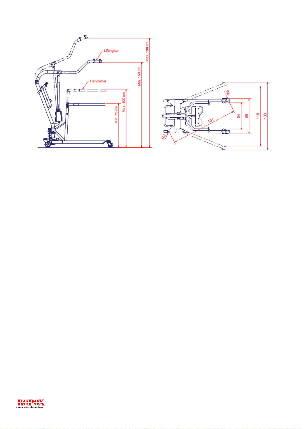
3.11 Product dimensions..................................................................................................................... 9
3.12 Complaints and adverse events................................................................................................ 10
4. Instructions for use................................................................................................................................ 11
4.1 Installation of product............................................................................................................... 11
4.2 Installation of liftig unit and hand support ................................................................................ 12
4.3 Operating the product.............................................................................................................. 14
4.3.1 Operating instructions........................................................................................................... 14
4.3.2 Emergency situation............................................................................................................. 14
4.4 Recharging the battery ............................................................................................................ 14
4.5 Safety function, liftingmotor ..................................................................................................... 15
4.6 Safety function, control unit ..................................................................................................... 15
4.7 Emergency lowering ................................................................................................................ 15
4.8 Brakes...................................................................................................................................... 16
4.9 Transfer –walking trainer............................................................................................................ 17
4.9.1 Lifting from chair/wheelchair................................................................................................. 17
4.9.2 Using the walking trainer...................................................................................................... 18
4.10 Height adjustment of hand support........................................................................................... 19
4.11 Electrical component diagram................................................................................................... 20
5. Trouble shooting .................................................................................................................................... 21
6. Cleaning .................................................................................................................................................. 21
7. Maintenance............................................................................................................................................ 22
7.1 Periodic maintenance .............................................................................................................. 22
7.2 Daily check............................................................................................................................... 22
7.3 Monthly maintenance............................................................................................................... 22
7.4 Yearly inspection ..................................................................................................................... 23
7.5 Maintenance report mechanical parts ..................................................................................... 24

TF 200.01.0016_ENG
3
7.6 Maintenance report actuator/lifting motor................................................................................ 25
7.7 Lifetime of actuator/liftingmotor................................................................................................ 26
8. Components part list.............................................................................................................................. 27
8.1 Spare parts.................................................................................................................................. 27
9. Environmental protection...................................................................................................................... 28
10. Electro magnetic compability ............................................................................................................... 28
10.1 Suitable Environments......................................................................................................... 28
10.2 Cables.................................................................................................................................. 28
10.3 RF portable equipment........................................................................................................ 28

TF 200.01.0016_ENG
4
1. Symbols used in this manual
Warning Symbol
Indication of potentially hazardous situation. If not avoided it can
result in serious injury or death.
Caution Symbol
Indication of potentially hazardous situation which may result in
minor or moderate injury.
It may also be used to alert against unsafe practices.
Notification Symbol
This symbol is used to notify correct use and handling of the
product.
2. General safety
This manual must be read and understood before use.
Always keep this manual in close proximity of the product.
The use, installation and service of this product must be in
compliance with this manual to avoid accidents and serious
personal injury.
Never use or handle this product in other ways specified in
this manual as it can result in personal safety hazards and/or
cause damage to the product.
Persons installing and/or using this product either as operator
or user should have the necessary safety information and
access to this manual.
If the supply cord is damaged, it must be replaced by the
manufacturer, its service agent or similarly qualified
designated persons in order to avoid a hazard.

TF 200.01.0016_ENG
5
Do not perform repairs, disassembly or assembly operations,
add-ons, re-adjustments or modification of the product
beyond what is described in this manual. These must be
carried out by Ropox or Ropox authorized personnel. Do not
perform service while in use.
This appliance can be used by children aged from 8 years
and above and persons with reduced physical, sensory or
mental capabilities or lack of experience and knowledge if
they have been given supervision or instruction concerning
use of the appliance in a safe way and understand the
hazards involved. Children shall not play with the appliance.
Cleaning and user maintenance shall not be made by
children without supervision.
Do not use the product if it has defects or have become
damaged before being repaired or replaced.
If the control box makes unusual noise or smells, switch off
the mains voltage immediately.
Take care that the cables are not damaged.
Unplug the mains cable on mobile equipment before it is
moved.
The products must only be used in an environment that
corresponds to their IP protection.
The information in this manual is based on correct installation
in accordance with installation instructions for this product.
Ropox cannot be held liable if the product is used in any way
that differs from stated in this manual and/or installation
instruction.
Ropox reserve the right to amend this manual and reference
documents without prior notice.

TF 200.01.0016_ENG
6
2.1 Product Unit label
This product is CE-marked in accordance with:
European Medical Device Directive 93/42/EEC, including
amendments incorporated in Directive 2007/47/EEC.
European Medical Device Regulation (EU)2017/745
Council Directive 2006/42/EC on machinery
Council Directive 2011/65/EU, RoHS
Manufacturer name and address
Date of production
Stock number
Serial number
Consult manual before use
Operating interval of electrically operated equipment. The use of electrical
height adjustable equipment can run at maximum 2 minutes, followed by an
18-minute break.
Type B applied part. The product complies with IEC 60601-1 requirements
to provide protection against electric shock.
Consult manual for important safety related information, warnings and safety
precautions.
Class II, double isolated electrical components.
Do not dispose as unsorted municipal waste. Product must be returned to a
designated recycling station.
Mobile phones or other portable RF emitting equipment should be no closer
to the product than 30cm.
Operating and storing temperatures may not exceed 5-40C°

TF 200.01.0016_ENG
7
2.2 Sales and transport packaging
Transport packaging label
Sales packaging label
3. General requirements
3.1 Product information
Manufacturer:
Product models
Part number
Model
Configuration
UDI
25-20035-8
25-20526-8
Walking trainer 150kg
Walking trainer 200kg
Combined
Not convertible
57075810810S6
57075810811S8
MDD Class
93/68/EEC
MDR Class
2017/745
Class I
Applied part
classification
60601-1
Type B applied part
MEE Class
60601-1
Class II
Intended environments
This product is to be used only in:
Proffesional Healtcare Environment
Homecare Environment
The device is not intended for use in special environments as defined by IEC
60601-1-2
Maximum user weight
according to DS/EN
10535:2007
150/200kg
Power supply
100-240V ~50/60Hz
I in
Max 2.5A
Intermittence
2min use / 18min pause
Height adjustment
150-190cm
Speed of actuation
≈15mm/s
IP rating
IPX4
Ambient temperature
range
-5 °C to +40 °C Transport and storage
+5 °C to +40 °C Operation
Relative humidity:
20% to 80% - non-condensing
Materials in contact
with patient
Sling
Spreader bar
Polyester
St37 tube construction
with powder coating.

TF 200.01.0016_ENG
8
Accessories
Item Number
25-20135-8
Model/specification
Walking Trainer kit
3.2 Product description
The all in one walking trainer system is a mobile personal lifter for people with limited mobility who need help
with walking training. The health staff can lift people up to 150/200 kg by using different sails.
3.3 Intended purpose
The product is used in situations where a patient must be lifted from a sitting position and up to a standing
position. The product must not be used for patient transport. The product must always be used with Ropox
suitable lifting slings.
3.4 Intended population
Patient with mobility difficulties.
3.5 Intended operator
Intended operator must have relevant health professional training before using the product, as well as have
read and understood this guide. Children, patient or lay person is not considered a suitable operator.
3.6 Essential performance
The lifting motor has a mechanical emergency lowering facility. In case of failure of electronics during use,
this can be used to lower the patient to a safe height.
3.7 Basic safety
The battery must always be checked for capacity before starting work. An audible warning will sound if the
battery capacity is too low. The product is equipped with an emergency stop, its function must also be
checked before use.
3.8 Non clinical functions
The product has no clinical effect. This is a patient lifter.

TF 200.01.0016_ENG
9
3.9 Product dimensions
25-20035
150kg
25-20526
200kg
Lifting capacity
150 kg
200 kg
Min. lifting height, lifting hook
150 cm
150 cm
Max. lifting height, lifting hook
190 cm
190 cm
Lifting travel
40 cm
40 cm
Min. height of handle
75 cm
75 cm
Max. height of handle
105 cm
105 cm
Width of handle
65 cm
65 cm
Length of undercarriage
117 cm
122 cm
Length legs
97 cm
98 cm
Min. inside distance between legs
50 cm
54 cm
Max. inside distance between legs
94 cm
118 cm
Min. outside distance between legs
65 cm
69 cm
Max. outside distance between legs
109 cm
133 cm
Height of undercarriage
12 cm
12 cm
Free height under legs
7 cm
7 cm
Wheel diameter
100/75 cm
100/75 cm
Turning circle
125 cm
131 cm
Weights
Weight of spreader bar (lifting unit)
5.0kg
5.0 kg
Weight of handle unit
8.5 kg
8.5 kg
Weight of battery
3.0 kg
3.0 kg
Total weight
55.0 kg
61.5 kg
Approx. number of lifting operations per
charging
60
30

TF 200.01.0016_ENG
10
3.12 Complaints and adverse events
Any serious incident that has occurred in relation to the device should be reported to the manufacturer and
the competent authority of the Member State in which the user and/or patient is located.

TF 200.01.0016_ENG
11
4. Instructions for use
4.1 Installation of product
Note! Assembly of 150kg and 200kg Walking
Trainers is identical. The only difference is the
undercarriage.
•Place the lifting mast in the mast holder of
the frame. Tighten the two screws with the
5mm Insex wrench provided, and use
locking nut on opposite site.
•Connect the cable from the leg spreading
motor to the control unit in output terminal 2,
see “Electrical component diagram”
Screws
M6 l
Screws

TF 200.01.0016_ENG
12
4.2 Installation of liftig unit and hand support
•Brake the rear wheels.
•Hold the lifting unit (turn it through 90°) so that the locking pin may be pushed into the corresponding
slide rail of the lifting mast.
•Push in the lifting unit.
•Now turn it 90° clockwise until a click is heard from the locking screw.
•Check that the arm has been properly locked.
•Hook the hand support on to the mast holder.
•Tighten the tightening handle on the side.
The walking trainer is now ready for use.
Tightening
handle
Locking pin

TF 200.01.0016_ENG
13
Dismounting
•Brake the rear wheels.
•Loosen the tightening handle.
•Note! Do not unscrew it completely.
•Lift the hand support off the mast holder.
•Note! It may be stuck owing to the clamping plates.
•Pull the locking screw while turning the spreader bar 90° counter-clockwise.
•The lifting unit may now be pulled out
Note! Be aware of the weight of the lifting unit.
Mounting of directional steering of the front wheels
•Dismount the M10x45 countersunk screw with washer and nut keeping the wheel in place.
•Mount plate and holder for steering using the new M10x50 countersunk screw.
Nut and
washer
M10 screw
With
steering
Without
steering
divice
Front
wheel

TF 200.01.0016_ENG
14
4.3 Operating the product
NOTE!
It is important that you are familiar with the use of the hoist and its functions, and that it
works properly. So for the best possible safety, all users of the hoist must read this user
manual before using the hoist.
For the All-in-One you can use any of Ropox Domino slings.
4.3.1 Operating instructions
-Check that the emergency stop has been released. If not, turn the button clockwise until release.
-The hoist is operated by means of the hand control unit. The two upper buttons control the lifting/lowering
movement, whereas the two lower buttons control the leg spreading facility. It is not possible to use two
functions simultaneously.
-Check that the sling provided is correct for the lifting operation to be performed. This applies to size as well
as shape. Further information about the choice of slings will be found in ”Domino Slings User manual”.
-The battery should be recharged regularly, to ensure that the hoist is always available (e.g. every night).
4.3.2 Emergency situation
Emergency stop and emergency lowering (electrical and mechanical) should be used in emergencies only.
Should it be necessary to activate the emergency functions, contact the distributor before using the hoist again.
4.4Recharging the battery
-The battery must be recharged after approx. 60 lifting operations –i.e. at 50% battery capacity. In case of
continued use you will hear an acoustic signal. The battery can still be used, but it will affect is recharging
capability.
-We recommend charging as soon as the hoist is not being used for a longer period of time, e.g. every night.
The battery cannot be over-charged and it is only ”healthy” for the battery to be recharged often as it
increases the battery life.
-Charging is made directly in the control unit by means of the mains cable provided. Insert the cable into the
wall outlet and the control unit, see drawing page 12, and switch on power. The hoist cannot be used when
connected to mains voltage.
-A green light on the control unit indicates connection to mains voltage. A yellow light indicates that the
battery is being recharged.
-When the battery has been fully charged, the yellow light will be out.
-Full recharging takes 4-5 hours.
-If charging is made via a wall-mounted charging station (optional) a battery may be constantly charged in
the station. The batteries may be easily switched by means of the snap system on top of the battery box.
NOTE!
In case of erroneous operation of the hand control unit (e.g. too quick change of
direction) the hoist does not react. Let go of the push button –wait a few seconds and
press again.
Warning!
The product should always be able to travel the full range of actuation without colliding
with objects. Failing to do so will compromise the product stability.
Special care should be taken in ensuring that no children or adults are sited under the
product as severer injury from entrapment may occur.

TF 200.01.0016_ENG
15
4.5Safety function, liftingmotor
The lifting motor is provided with a safety function, splejn, against jamming. If the lifting arm meets with
resistance during lowering, the movement of the arm will stop automatically. Thus, a person cannot get
jammed between the lifting arm and the bed.
4.6Safety function, control unit
-protective motor switch for lifting and leg spreading, protecting against overloading
-short-circuit protection
-acoustic signal sounding when the batteries need charging
-electrical emergency lowering if the hand control unit does not work
-built-in charger
Emergency stop
If the hoist is to be stopped owing to an emergency –press the red button on the control unit. When the
button has been depressed the electrical functions of the hoist cannot be activated and the battery indicator
has been switched off.
4.7Emergency lowering
If the hoist is to be lowered and the hand control unit does not work, there are two possible solutions:
-The electrical emergency lowering of the control unit (marked emergency), see drawing page 21. Press
with a ball pencil or the like and the person will be lowered slowly.
-The mechanical emergency lowering of the lifting motor. Pull up the red handle, see drawing.
NOTE!
Make sure that the plug from the battery is correctly inserted in the control box, if the plug
have been pulled out, before using the lift again.
WARNING!
Owing to the safety function on the motor the lifting arm and spreader bar may fall freely
to the spindle of the motor.
Therefore make sure that the lifting arm does not ”hang”, that is
has always been pressed down to ensure that it rests on the
spindle of the motor before and after all lifting operations. This
is important as otherwise an injury may result if the lifting arm
”falls” down.

TF 200.01.0016_ENG
16
4.8Brakes
The hoist may be braked on
the two large rear wheels.
Press down the rear part of the
brake with the foot to brake the
hoist. Release the brake by
pressing the front part of the
brake with the foot.
NOTE!
Never brake the hoist during lifting except when used in stand-up mode.
Brake
Release
The lifting motor has a mechanical
emergency lowering facility. To release
it, pull the red handle.

TF 200.01.0016_ENG
17
4.9 Transfer –walking trainer
•Before lifting a person it is important to be familiar with the walking trainer and that it works satisfactorily.
•Also, it is important to choose the right size of sling for the lifting operation to be performed. Further
information about the use of slings will be found in the ”Walking Trainer Manual for Slings”.
•We recommend that the walking training take place on a horizontal surface. However, the walking trainer
may be used on surfaces with gradients up to 5°.
•Never lift a person higher than necessary.
•Always observe the maximum load of the hoist.
4.9.1 Lifting from chair/wheelchair
•Place the sling around the client sitting in the chair/wheelchair. Close the body belt and tighten it so that it
is still comfortable.
•Place the leg straps between the thighs and pull the lifting straps placed in front of the shoulders through
the black loops of the leg straps. Make sure that the four grey lifting straps are in the same height before
attaching them to the spreader bar.
•Increase the width between the legs of the hoist and move it towards the client.
•Place the feet of the client on the floor.
•Move the hoist so close to the client as possible.
•Make sure that the spreader bar is in the lower position.
•Place the lifting straps of the sling correctly in the hooks of the spreader bar. Check that all straps have
been fitted correctly.
•Lift the client a few centimetres above the seat - STOP –and make sure that the sling is placed correctly.
•When the client is comfortable, lift him/her from the chair to standing position.
•Slowly pull the hoist away from the chair - STOP –adjust the sling and lifting height until the client is
standing comfortably.
•You may now start walking training.
Before lifting a client, try the hoist yourself.
Risk assessment shall be carried out to ensure that the correct size, type and shape of
slings is being used for the patient.
NOTE!
The wheelchair must be braked during transfer to and from the chair.

TF 200.01.0016_ENG
18
4.9.2 Using the walking trainer
•The carer may walk in front of or beside the
walking trainer, instructing or supporting
the client.
•Raising or lowering the sling frame will
relieve the client depending on the phase
of walking training.
•Use the hand support to begin with in order
to give the client something to hold on to
and to use for pushing/steering.
•During the last phase of the walking training the
client may use the hand support only without the
support of the sling.
•The steering devices of the two front wheels
contribute to steering the walking trainer, e.g. when
persons with hemiplegia start walking training.
4.9.2 Placing in chair/wheelchair
To place a person in a chair/wheelchair, do the procedures on the opposite side in reverse order:
•Increase the width between the legs of the walking trainer and move it to the chair.
•Make sure that the client is positioned correctly above the chair and lower the hoist slowly.
•Check that the client is positioned correctly during the entire operation.
•When assisting a client in getting back into the chair, lower the client so that he/she just touches the chair.
•If the chair can be tilted a little backward it is easier to place the client correctly.
•If two assistants are present, one may press gently on the knees of the client.

TF 200.01.0016_ENG
19
4.10 Height adjustment of hand support
Press red button, afterwards pull locking tap. Hand support can now be pulled upwards or pushed
downwards for adjustment of correct height for user.

TF 200.01.0016_ENG
20
4.11 Electrical component diagram
Plug for charging, mains cable
Lifting motor
Leg spreading motor
Hand control unit
Emergency
stop
Emergency lowering
Charging indicator
Connected to
mains voltage
This manual suits for next models
3
Table of contents
Other Ropox Fitness Equipment manuals