Quick Installation Guide
00825-0100-4809, Rev DB
December 2009
Flanged 485 Annubar
10
STEP 4: WELD MOUNTING HARDWARE
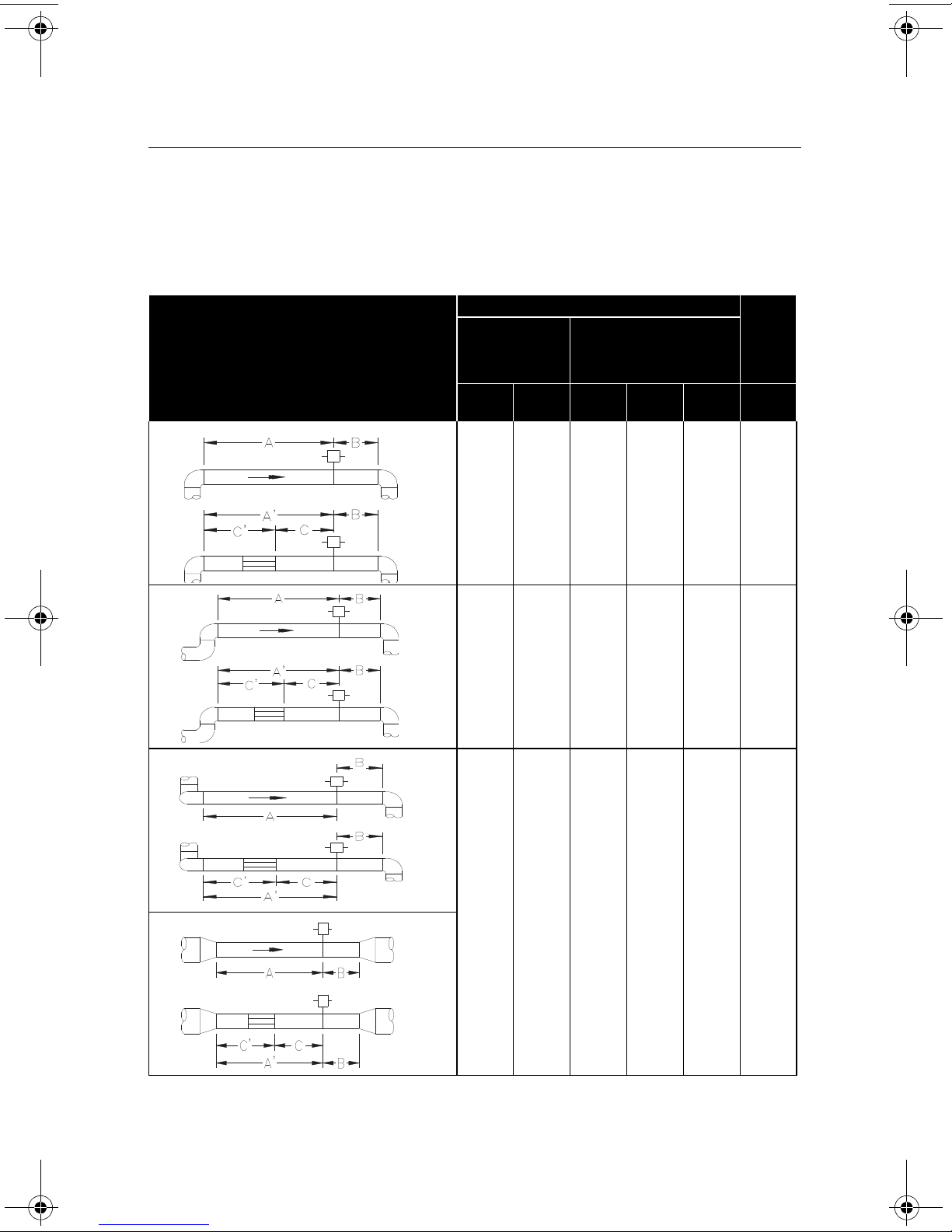
1. Center the flanged assembly over the mounting hole, gap 1/16-in. (1,6 mm), and measure
the distance from the outer diameter of the pipe to the face of the flange. Compare this to
Table 3 and adjust the gap as necessary.
Table 3. Flange Sizes and ODF Per Sensor Size
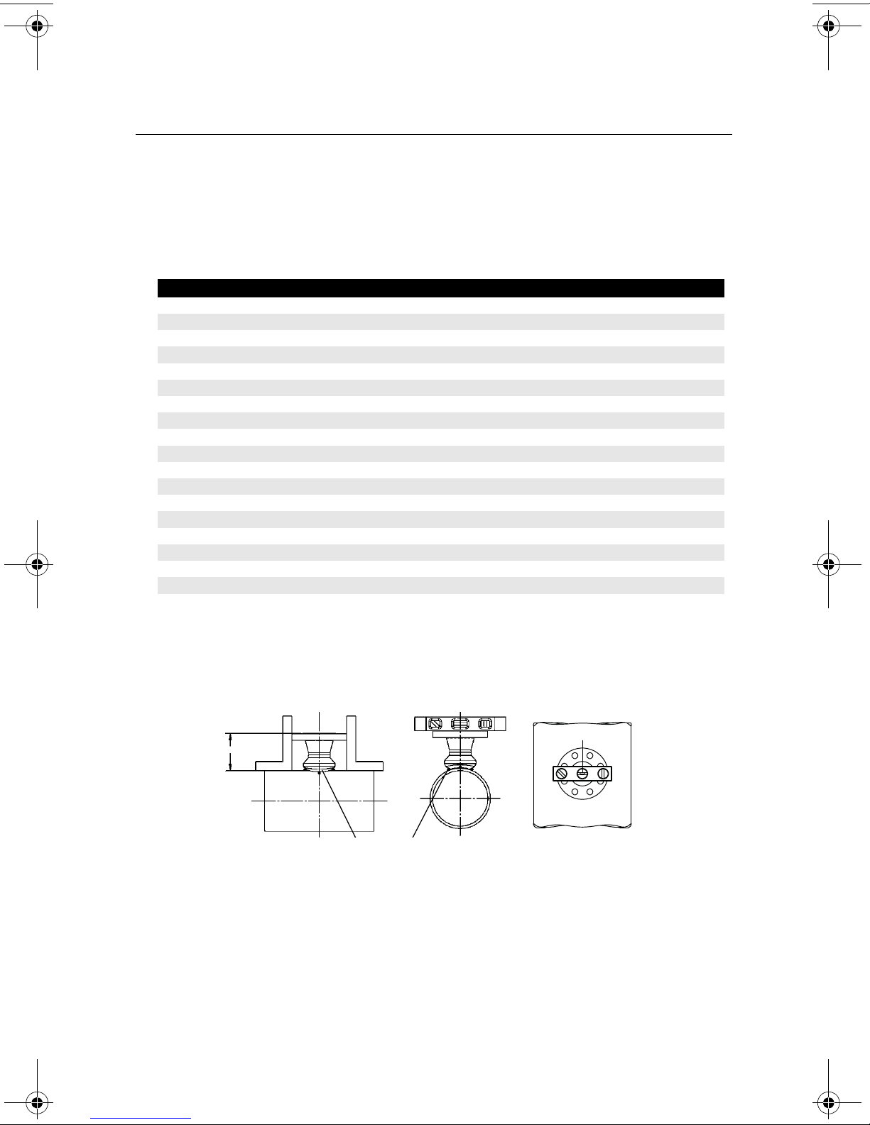
2. Place four 1/4-in. (6 mm) tack welds at 90° increments. Check alignment of the mounting
both parallel and perpendicular to the axis of flow (see Figure 9). If alignment of the
mounting is within tolerances, finish weld per local codes. If alignment is outside of
specified tolerance, make adjustments prior to making the finish weld.
Figure 9. Alignment
3. If opposite-side support is being used, center the fitting for the opposite side support over
the opposite side hole, gap 1/16-in. (1,6 mm), and place four 1/4-in. (6 mm) tack welds at
90° increments. Insert the sensor into the mounting hardware. Verify that the tip of the
sensor is centered in the opposite side fitting and the plug will fit around sensor. Finish
weld per local codes. If alignment of the sensor does not allow enough clearance to
insert the opposite side plug, make the necessary adjustments prior to making the finish
weld.
4. To avoid serious burns, allow the mounting hardware to cool before continuing.
Sensor Size Flange Size ODF (in. (mm)) Size ODF (in. (mm)
11
1/2-in. 150# 3.88 (98.5) DN40 PN16 3.09 (78.6)
1 11/2-in. 300# 4.13 (104.9) DN40 PN40 3.21 (81.6)
11
1/2-in. 600# 4.44 (112.7) DN40 PN100 3.88 (98.6)
1 11/2-in. 900# 4.94 (125.4) Not Applicable Not Applicable
11
1/2-in. 1500# 4.94 (125.4) Not Applicable Not Applicable
1 11/2-in. 2500# 6.76 (171.6) Not Applicable Not Applicable
2 2.0-in. 150# 4.13 (104.8) DN50 PN16 3.40 (86.3)
22.0-in. 300# 4.38 (111.2) DN50 PN40 3.51 (89.3)
2 2.0-in. 600# 4.76 (120.8) DN50 PN100 4.30 (109.3)
22.0-in. 900# 5.88 (149.2) Not Applicable Not Applicable
2 2.0-in. 1500# 5.88 (149.2) Not Applicable Not Applicable
23.0-in. 2500# 9.87 (250.7) Not Applicable Not Applicable
3 3.0-in. 150# 4.63 (117.5) DN80 PN16 3.84 (97.6)
33.0-in. 300# 5.00 (126.9) DN80 PN40 4.16 (105.6)
3 3.0-in. 600# 5.38 (136.6) DN80 PN100 4.95 (125.6)
34.0-in. 900# 8.19 (208.0) Not Applicable Not Applicable
3 4.0-in. 1500# 8.56 (217.5) Not Applicable Not Applicable
34.0-in. 2500# 11.19 (284.2) Not Applicable Not Applicable
0100-4809 Rev DB.fm Page 10 Wednesday, December 30, 2009 3:57 PM