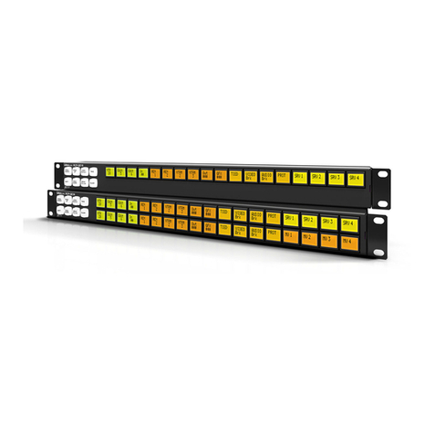
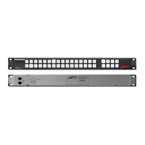
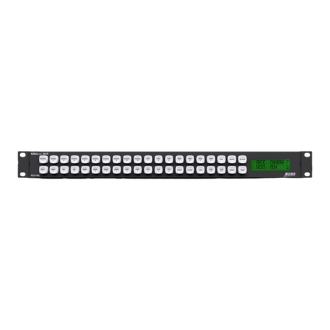
Ross NK RCP-NKM User manual

RCP-NKM User Guide

Thank You for Choosing Ross
You've made a great choice. We expect you will be very happy with your purchase of Ross Technology.
Our mission is to:
1. Provide a Superior Customer Experience
• offer the best product quality and support
2. Make Cool Practical Technology
• develop great products that customers love
Ross has become well known for the Ross Video Code of Ethics. It guides our interactions and
empowers our employees. I hope you enjoy reading it below.
If anything at all with your Ross experience does not live up to your expectations be sure to reach out to
us at [email protected].
David Ross
CEO, Ross Video
Ross Video Code of Ethics
Any company is the sum total of the people that make things happen. At Ross, our employees are a
special group. Our employees truly care about doing a great job and delivering a high quality customer
experience every day. This code of ethics hangs on the wall of all Ross Video locations to guide our
behavior:
1. We will always act in our customers’ best interest.
2. We will do our best to understand our customers’ requirements.
3. We will not ship crap.
4. We will be great to work with.
5. We will do something extra for our customers, as an apology, when something big goes wrong and
it's our fault.
6. We will keep our promises.
7. We will treat the competition with respect.
8. We will cooperate with and help other friendly companies.
9. We will go above and beyond in times of crisis. If there's no one to authorize the required action in
times of company or customer crisis - do what you know in your heart is right. (You may rent
helicopters if necessary.)

RCP-NKM · User Guide
• Ross Part Number: 9806DR-0103-03
• Release Date: August 15, 2019.
The information contained in this Guide is subject to change without notice or obligation.
Copyright
©2019 Ross Video Limited, Ross®, and any related marks are trademarks or registered trademarks of Ross Video Limited. All other
trademarks are the property of their respective companies. PATENTS ISSUED and PENDING. All rights reserved. No part of this
publication may be reproduced, stored in a retrieval system, or transmitted in any form or by any means, mechanical, photocopying,
recording or otherwise, without the prior written permission of Ross Video. While every precaution has been taken in the preparation
of this document, Ross Video assumes no responsibility for errors or omissions. Neither is any liability assumed for damages resulting
from the use of the information contained herein.
Patents
Patent numbers US 7,034,886; US 7,508,455; US 7,602,446; US 7,802,802 B2; US 7,834,886; US 7,914,332; US 8,307,284; US
8,407,374 B2; US 8,499,019 B2; US 8,519,949 B2; US 8,743,292 B2; GB 2,419,119 B; GB 2,447,380 B; and other patents pending.
Notice
The material in this manual is furnished for informational use only. It is subject to change without notice and should not be construed
as commitment by Ross Video Limited. Ross Video Limited assumes no responsibility or liability for errors or inaccuracies that may
appear in this manual.
Statement of Compliance
This product has been determined to be compliant with the applicable standards, regulations, and directives for the countries where
the product is marketed.
Compliance documentation, such as certification or Declaration of Compliance for the product is available upon request by
contacting techsupport@rossvideo.com. Please include the product; model number identifiers and serial number and country that
compliance information is needed in request.
EMC Notices
US FCC Part 15 Sub Part B
This equipment has been tested and found to comply with the limits for a class A Digital device, pursuant to part 15 of the FCC Rules.
These limits are designed to provide reasonable protection against harmful interference when the equipment is operated in a
Commercial environment. This equipment generates, uses, and can radiate radio frequency energy and, if not installed and used in
accordance with the instruction manual, may cause harmful interference to radio communications. Operation of this equipment in a
residential area is likely to cause harmful interference in which case the user will be required to correct the interference at his own
expense.
CANADA
This Class “A” digital apparatus complies with Canadian ICES-003.
Cet appareil numerique de la classe “A” est conforme a la norme NMB-003 du Canada.
EUROPE
This equipment is in compliance with the essential requirements and other relevant provisions of Council Directives 2006/95/EC &
2004/108/EC.
Notice — Changes or modifications to this equipment not expressly approved by Ross Video Ltd. could void the
user’s authority to operate this equipment.

INTERNATIONAL
This equipment has been tested to CISPR 22:1997 along with amendments A1:2000 and A2:2002 and found to comply with the
limits for a Class A Digital device.
Australian/New Zealand C-tick approval
The equipment meets the requirements of the Australian Communications and Media Authority (Limits & Methods of Measurement
of Radio Interference Characteristics of Information Technology Equipment (AS/NZS CISPR22)).
Warranty and Repair Policy
The product is backed by a comprehensive one-year warranty on all components.
If an item becomes defective within the warranty period Ross will repair or replace the defective item, as determined solely by Ross.
Warranty repairs will be conducted at Ross, with all shipping FOB Ross dock. If repairs are conducted at the customer site, reasonable
out-of-pocket charges will apply. At the discretion of Ross, and on a temporary loan basis, plug in circuit boards or other replacement
parts may be supplied free of charge while defective items undergo repair. Return packing, shipping, and special handling costs are
the responsibility of the customer.
This warranty is void if products are subjected to misuse, neglect, accident, improper installation or application, or unauthorized
modification.
In no event shall Ross Video Limited be liable for direct, indirect, special, incidental, or consequential damages (including loss of
profit). Implied warranties, including that of merchantability and fitness for a particular purpose, are expressly limited to the duration
of this warranty.
This warranty is TRANSFERABLE to subsequent owners, subject to Ross’ notification of change of ownership.
Extended Warranty
For customers that require a longer warranty period, Ross offers an extended warranty plan to extend the standard warranty period by
one year increments. For more information, contact your regional sales manager.
Environmental Information
The equipment that you purchased required the extraction and use of natural resources for its production. It may contain hazardous
substances that could impact health and the environment.
To avoid the potential release of those substances into the environment and to diminish the need for the extraction of natural
resources, Ross Video encourages you to use the appropriate take-back systems. These systems will reuse or recycle most of the
materials from your end-of-life equipment in an environmentally friendly and health conscious manner.
The crossed-out wheeled bin symbol invites you to use these systems.
If you need more information on the collection, reuse, and recycling systems, please contact your local or regional waste
administration. You can also contact Ross Video for more information on the environmental performances of our products.
Notice — This is a Class A product. In domestic environments, this product may cause radio interference, in which
case the user may have to take adequate measures.
Notice — Changes or modifications to this equipment not expressly approved by Ross Video Ltd. could void the
user’s authority to operate this equipment.

Company Address
Ross Video Limited
8 John Street
Iroquois, Ontario
Canada, K0E 1K0
Ross Video Incorporated
P.O. Box 880
Ogdensburg, New York
USA 13669-0880
General Business Office: (+1) 613 652 4886
Fax: (+1) 613 652 4425
Technical Support: (+1) 613 652 4886
After Hours Emergency: (+1) 613 349 0006
E-mail (Technical Support): [email protected]
E-mail (General Information): [email protected]
Website: http://www.rossvideo.com


RCP-NKM User Guide (v3.0) Contents • i
Contents
Introduction 1
Overview of this User Guide ................................................................................................................................1-1
RCP-NKM Overview 2
Features ..................................................................................................................................................................2-1
Typical System Equipment ....................................................................................................................................2-1
System Overview ...................................................................................................................................................2-2
How the RCP-NKM and Routing Switchers Communicate..................................................................................2-3
Installation 3
Unpacking the Equipment......................................................................................................................................3-1
General...................................................................................................................................................................3-1
Installing the RCP-NKM .......................................................................................................................................3-1
Connecting to the NK-IPS in the Routing Switcher System .................................................................................3-3
Checking the Firmware Version of a Device.........................................................................................................3-4
Upgrading the Firmware Version of a Device .......................................................................................................3-4
Setting Up the RCP-NKM 4
Implementing Your System Plan ...........................................................................................................................4-1
Viewing and Changing Device Details..................................................................................................................4-2
Default Configuration ............................................................................................................................................4-3
Linking Remote Control Panels.............................................................................................................................4-4
Assigning Physical Connections for Control by an RCP-NKM ............................................................................4-5
Setting Up Breakaways..........................................................................................................................................4-6
Setting Up Menus ..................................................................................................................................................4-7
Assigning Functions to Keys on the RCP-NKM ...................................................................................................4-8
Unassigning a Key ...............................................................................................................................................4-18
Locking an RCP-NKM ........................................................................................................................................4-18
Setting Up Cutbus Operation ...............................................................................................................................4-18
Setting Up Machine Control ................................................................................................................................4-19
Setting Up Virtual Routing and Resource Management......................................................................................4-20
Setting the Retry Time for a Switch Failure ........................................................................................................4-21
Setting Up the Backlighting on the RCP-NKM...................................................................................................4-21
Returning to the Home Menu ..............................................................................................................................4-21
Loading Factory Defaults ....................................................................................................................................4-22
Saving the Current Document for the RCP-NKM...............................................................................................4-22
Sending a Document to a Device.........................................................................................................................4-23
Printing Labels for the Front of the RCP-NKM ..................................................................................................4-23
Operating the RCP-NKM 5
LCD Screen............................................................................................................................................................5-1
Breakaways and Levels..........................................................................................................................................5-2
Making a Switch ....................................................................................................................................................5-3
Using a Macro........................................................................................................................................................5-4
Locking the RCP-NKM .........................................................................................................................................5-4
Protecting a Destination.........................................................................................................................................5-5
Clearing Protects Held by an RCP-NKM ..............................................................................................................5-6
Toggling Between Two Sources ............................................................................................................................5-6
Using a Menu.........................................................................................................................................................5-7

ii • Contents RCP-NKM User Guide (v3.0)
De-Assigning a Machine Control Port .................................................................................................................. 5-7
De-Assigning Resources ....................................................................................................................................... 5-8
Operating Linked Remote Control Panels ............................................................................................................ 5-8
Resetting Devices.................................................................................................................................................. 5-9
Viewing Status and Alarms................................................................................................................................... 5-9
Adjusting the Contrast for the LCD .................................................................................................................... 5-10
Troubleshooting 6
Hexadecimal to Router Level Conversion 7

RCP-NKM User Guide (v3.0) Introduction • 1–1
Introduction
Thank you for purchasing the Ross Video RCP-NKM Remote Control Panel. This remote control panel enables you
to control a routing switcher system from one point. With Ross Video’s reputation for delivering leading-edge
routing switcher equipment and our unsurpassed level of customer service and support, you can look forward to
many years of reliable broadcasting. Please read this thoroughly and retain it for future reference.
The RCP-NKM provides flexible connectivity of additional remote control panels and multi-page menu
programming.
Overview of this User Guide
This is for installers, and operators of the Ross Video RCP-NKM. It provides instructions on how to connect the
RCP-NKM to your routing switcher system, how to set up a configuration document for the RCP-NKM using
DashBoard, and how to operate it. It assumes that you are experienced with general broadcast concepts, and that
you are familiar with the planning requirements for a routing switcher system.

1–2 • Introduction RCP-NKM User Guide (v3.0)

RCP-NKM User Guide (v3.0) RCP-NKM Overview • 2–1
RCP-NKM Overview
Features
The RCP-NKM Remote Control Panel provides the following features:
• 40 programmable keys (function, backlighting level)
• 16 character × 2 line backlit LCD
• operation in XY and cutbus modes
• up to 32 router levels may be controlled
• virtual routing and resource management
• macros
• panel linking with other remote control panels
• DashBoard support for easy creation of configuration documents
• firmware is fully upgradeable using DashBoard
• slim modular design integrates with NK Series devices via T-Bus using straight CAT5 Ethernet cables
• custom transparent labels under keys
• up to 250 pages of programmable menus including navigation keys
• assignable functions of destination, source, crosspoint, level, breakaway, breakaway step, macro, protect, take,
chop, shift, de-assign, machine control, panel lock, menu link, and menu navigation
Typical System Equipment
The RCP-NKM is used when you require advanced control functions from a single point. Using DashBoard, you
can program up to 250 menus on the same remote control panel. At each menu, the function of particular keys may
change depending on the assignment. These parameters can be saved in a configuration document and sent to an
RCP-NKM at any time using DashBoard. Therefore, if an RCP-NKM is used in a number of different operating
scenarios, the configuration can be changed easily and quickly.
Typical equipment that is used in an NK Series routing switcher system when an RCP-NKM is used includes:
• any of the NK Series routing switchers with its appropriate power supply (for more information see the
documentation provided with your NK Series routing switcher)
• an NK-IPS Network Bridge
• a PC running DashBoard, connected via a CAT5 Ethernet cable to the NK-IPS
• standard source and destination equipment (for example, cameras, VTRs, servers)
Notes
Keep the following in mind:
• If you are connecting the PC directly to the NK-IPS, use a crossover CAT5 Ethernet cable.
• If you are connecting the PC indirectly via an Ethernet switch to the NK-IPS, use a straight-through CAT5
Ethernet cable.
• The NK-IPS and PC with DashBoard are only required for setting up the configuration document, then sending
this to the device. However, you can use the NK Switchboard feature in DashBoard to control and monitor a
routing switcher system.

2–2 • RCP-NKM Overview RCP-NKM User Guide (v3.0)
System Overview
A routing switcher system may use distributed control across the internet, a LAN, or a VPN. The routing switcher
system shown in Figure 2.1 has been simplified.
Figure 2.1 Layout showing a simplified routing switcher system with an RCP-NKM
NK-D32/75 AES/EBU
Digital Audio Routing Switcher
Internet/LAN/VPN
PC running
DashBoard
Audio out
Audio out
Server 1
Server 2
VTR 1
VTR 2
Audio in
Server 3
Audio in
Video in
Audio in
Monitor
Appropriate
NK Series
power supply
Input 1
Input 2
Input 7
Output 15
Output 20
Output 8
Audio out
Audio out
Input 5
NK-IPS
Network Bridge
Appropriate
NK Series
power supply
RCP-NKM
Remote Control Panel
NK-S34 SDI
Digital Video Routing Switcher
Appropriate
NK Series
power supply
NK Series
5 V, 2 A
power supply
Video out
Video out
Video out
Input 5
Input 7
Input 3
Video in
Output 20
Output 8
Output 15
Video in
Camera 2
Camera 1
Ethernet
switch
Ethernet
T-BUS
T-BUS
T-BUS

RCP-NKM User Guide (v3.0) RCP-NKM Overview • 2–3
All T-Bus connections between NK Series devices use straight-through CAT5 cables.
How the RCP-NKM and Routing Switchers Communicate
Switching
The RCP-NKM sends a switch request message to the routing switcher. The routing switcher recognises the
request, sets the crosspoint, then sends a response to the RCP-NKM.
Data Storage
The RCP-NKM stores information on the menu, destination, level, breakaway, and machine control status. The
routing switcher stores the crosspoint status in its internal memory.
When the routing switcher system is powered up, the routing switcher restores its crosspoint status. The RCP-NKM
requests the status of the routing switcher. The routing switcher sends the status of the crosspoints to the
RCP-NKM

2–4 • RCP-NKM Overview RCP-NKM User Guide (v3.0)

RCP-NKM User Guide (v3.0) Installation • 3–1
Installation
Unpacking the Equipment
On receiving your RCP-NKM, check the contents against the packing list. Make sure that all equipment itemized on
the packing list is present and that there are no signs of damage before you start installing the RCP-NKM into your
system.
If anything is missing or damaged, contact your Ross Video office immediately to obtain the correct warranty
service procedures. This ensures prompt assistance, minimal turnaround time, and avoids any freight issues.
We recommend that the equipment is installed by qualified and experienced personnel, to any relevant standards
and approvals.
General
These installation guidelines assume the following:
• The relevant NK Series equipment has been installed into a ventilated rack frame. The relative humidity in the
environment of the equipment should be < 70% (non-condensing).
• The routing switcher system has been well planned and designed. Consideration must be given to inputs and
outputs across multiple router levels, and typical operating scenarios for breakaways.
• Correct IP addresses have been assigned to the equipment, where required.
• The routing switchers are connected to physical inputs and outputs, and have appropriate NK Series power
supplies.
• All NK Series equipment connected in the routing switcher system have firmware v2.00 or later. For information
on updating the firmware in a device see the readme file that comes with the firmware. To check for the latest
firmware versions, contact Ross Video Technical Support.
Installing the RCP-NKM
The RCP-NKM is powered using the 5 V 2 A power supply provided. This power supply connects directly to the
AC mains supply
Installing the Routing Switcher System in a Daisy-Chain Layout
You may connect NK Series equipment in a daisy-chain layout. The items are connected via the T-Bus control
system. However, if the T-Bus chain is broken, for example, by accidentally disconnecting a cable, downstream
devices are also disconnected. T-Bus RJ-45 sockets on devices downstream from the NK-IPS are passively
connected internally, so device failure or power disconnection does not disrupt communication with other devices
in the chain.
Each T-Bus connector on the NK-IPS has an independent driver/receiver ensuring that each of the eight T-Bus
connectors will not be affected by a device failure on any other connector.
Warning — Ensure that the AC mains supply complies with the PSU specification before making the
connection.
Warning — An earthed neutral mains supply and residual current device is recommended for safe
operation.

3–2 • Installation RCP-NKM User Guide (v3.0)
Figure 3.2 Remote control panels connected to NK Series equipment in a daisy-chain layout
To connect the remote control panel in a daisy-chain layout
1. Install the RCP-NKM into the rack frame, then fix in place with appropriate fasteners.
2. Connect a straight-through CAT5 Ethernet cable between a T- BUS connector on the rear of the RCP-NKM and
a T-BUS connector on the rear of another remote control panel, an NK Series routing switcher, or an NK-IPS
(see Figure 3.2).
If required, make a similar connection between the remaining T-BUS connector on the rear panel of the
RCP-NKM and a T-BUS connector on the rear panel of another item of NK Series equipment.
3. Connect the 5 V 2 A power supply provided to the POWER connector on the rear panels of the RCP-NKM.
4. Connect the cable from the power supply to a suitable AC mains supply.
The RCP-NKM is designed for installation into a standard 19" equipment rack. It has integrated rack ears,
allowing it to be screwed in using standard screws and cage nuts.
Installing the Routing Switcher System in a Star Layout
You may connect NK Series equipment to the NK-IPS in a star layout. The items are connected via the T-BUS
control system. If any device connected directly to the NK-IPS is disconnected, it is only the downstream devices
that become non-operational. All other devices remain operational.
NK-IPS
Network Bridge
RCP-NKM
Remote Control Panel
RCP-NKM
Remote Control Panel
Routing Switcher
Appropriate
NK Series
power supply
T-BUS
T-BUS
T-BUS
Appropriate
NK Series
power supply
NK Series
5 V, 2 A
powersupply
NK Series
5 V, 2 A
powersupply

RCP-NKM User Guide (v3.0) Installation • 3–3
Figure 3.3 Remote control panels connected to NK Series equipment in a star layout
To connect the remote control panel in a star layout
1. Install the RCP-NKM into the rack frame, then fix in place with appropriate fasteners.
2. Connect a straight CAT5 Ethernet cable between a T-Bus connector on the rear panel of the RCP-NKM and a
T-Bus connector on the rear panel of the NK-IPS (see Figure 3.3).
3. Connect the 5 V 2 A power supply provided to the POWER connector on the rear panel of the RCP-NKM.
4. Connect the cable from the power supply to a suitable AC mains supply.
5. Connect any remaining remote control panels in this manner.
The RCP-NKM is designed for installation into a standard 19" equipment rack. It has integrated rack ears,
allowing it to be screwed in using standard screws and cage nuts.
Connecting to the NK-IPS in the Routing Switcher System
Before you can set up and send a configuration document to the RCP-NKM, you must connect an NK-IPS to the
RCP-NKM. Once DashBoard locates the NK-IPS, the attached RCP-NKM is visible and can have configuration
documents sent to it.
Most systems automatically detect an NK-IPS if its IP address uses the same subnet as the PC running DashBoard.
However, if the device is not detected automatically, follow the steps below. For information on the NK-IPS, refer
to the documentation provided with the equipment.
To connect to the NK-IPS
1. Launch DashBoard.
2. Use Walkabout to determine and/or change the IP address of the NK-IPS. Refer to the NK-IPS User Guide for
more information.
3. From the main toolbar in DashBoard select File > New > NK IPS Connection.
NK-IPS
Network Bridge
RCP-NKM
Remote Control Panel
Routing Switcher
Appropriate
NK Series
power supply
T-BUS
NK Series
5 V, 2 A
powersupply
Routing Switcher
RCP-NKM
Remote Control Panel
RCP-NKM
Remote Control Panel
RCP-NKM
Remote Control Panel
NK Series
5 V, 2 A
powersupply
NK Series
5 V, 2 A
powersupply
NK Series
5 V, 2 A
powersupply
Appropriate
NK Series
power supply
T-BUS
T-BUS
T-BUS
Appropriate
NK Series
power supply
T-BUS T-BUS

3–4 • Installation RCP-NKM User Guide (v3.0)
4. Enter the IP Address of the NK-IPS you want to connect to.
5. Ensure the TCP Port field is set to 5000.
6. Click Finish.
The NK-IPS now displays as a node in the Basic Tree View of DashBoard.
Checking the Firmware Version of a Device
The RCP-NKM must operate with other devices that have v2.00 firmware or later. Firmware may be updated easily
using the DashBoard. To check for the latest firmware versions, contact Ross Video Technical Support.
Using DashBoard to Check the Firmware Version
To check the firmware version of any device using DashBoard
1. Launch DashBoard and connect to the NK-IPS.
2. In the Device Tree of DashBoard, expand the NK-IPS (or NK-NET) node to display a list of sub-nodes.
Each sub-node is a list of devices communicating with the NK-IPS (or NK-NET).
3. Double-click the RCP-NKM node to open its interface in DashBoard.
The firmware version is reported in the top panel of the window.
Upgrading the Firmware Version of a Device
For information on upgrading the firmware version of a device, see the readme file that comes with the firmware.

RCP-NKM User Guide (v3.0) Setting Up the RCP-NKM • 4–1
Setting Up the RCP-NKM
The RCP-NKM can be set up using the DashBoard. You must have an NK-IPS connected to the system. The
parameters for a device may be then saved to a configuration document.
For More Information on...
• checking and upgrading firmware, see “Checking the Firmware Version of a Device” on page 3–4 and
“Upgrading the Firmware Version of a Device” on page 3–4.
• saving parameters to a configuration document, see “Saving the Current Document for the RCP-NKM” on
page 4–22.
Opening the RCP-NKM Editor
Before setting up any parameters for the RCP-NKM, ensure that all NK Series devices in the routing switcher
system have firmware v2.00 or later.
To open the RCP-NKM editor
1. Launch DashBoard and connect to the NK-IPS.
2. In the Device Tree of DashBoard, expand the NK-IPS (or NK-NET) node to display a list of sub-nodes.
Each sub-node is a list of devices communicating with the NK-IPS (or NK-NET).
3. Double-click the RCP-NKM node to open its interface in DashBoard.
Implementing Your System Plan
An effective routing switcher system takes careful planning. If you intend to use multiple router levels across
several input and output devices, it is recommended that you use common input connectors for each source device
across the routing switchers, and common output connectors for each destination device across the routing
switchers. This methodology is shown in Figure 4.4.
The following process for setting up the RCP-NKM is recommended.

4–2 • Setting Up the RCP-NKM RCP-NKM User Guide (v3.0)
Figure 4.4 Flow chart for setting up the RCP-NKM
Viewing and Changing Device Details
When a device attached to the NK-IPS is interrogated, a tab for the device appears in the main pane of DashBoard.
Information is read from the device and shown in the simulated RCP-NKM.
To view the details for the RCP-NKM
1. Open the RCP-NKM editor (see “Opening the RCP-NKM Editor” on page 4–1).
The read-only parameters for the RCP-NKM are shown in the top section of the tab of the device.
Table 4.1 Device details that are read from the RCP-NKM
Item Description
Serial Num (read-only) This parameter is read-only. The serial number of the device. This is set in the factory.
It is unique to the device.
If you are working on a file that is stored under File Explorer, the serial number of
the device is replaced by SAVED-FILE.
Version (read-only) This parameter is read-only. The version status of the firmware detected in the device.
If the firmware version for any NK Series device that is connected to the RCP-NKM
is earlier than v2.00, you must upgrade the firmware in that device (see “Upgrading
the Firmware Version of a Device” on page 3–4).
Update device
details
Assign inputs and
outputs according
to physical
connections
Set up
breakaways
according to router
levels
Assign functions
to keys
Unassign any
keys that are not
used
Set up menus
Table of contents
Other Ross Control Panel manuals

Ross
Ross CARBONITE RCP Series User manual

Ross
Ross NK Routing Systems RCP-QE User manual

Ross
Ross TouchDrive User manual

Ross
Ross Ultritouch User manual

Ross
Ross Ultrix Acuity User manual

Ross
Ross Ultrix Acuity User manual

Ross
Ross Vision 4800DR-322-05 User manual

Ross
Ross Ultricore RCP-ME User manual

Ross
Ross PIVOTCam User manual

Ross
Ross Touch Drive User manual
Popular Control Panel manuals by other brands

Gamewell
Gamewell ZNS Installation & operation manual

Dometic
Dometic MPC01 Installation and operating manual

United Technologies
United Technologies Interlogix Advisor Advanced ATS1000A-SM Manager manual

EST
EST EST3X Installation sheet

GESTRA
GESTRA SPECTORcontrol user manual

Vallox
Vallox MyVallox Control manual