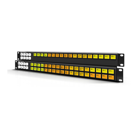
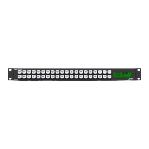
Ross Vision 4800DR-322-05 User manual

Ross Video Limited
Auxiliary Control Panel
Installation Guide
V I S I O N

2
Vision • Auxiliary Control Panel Installation Guide
• Ross Part Number: 4800DR-322-05
• Release Date: September 30, 2010. Printed in Canada.
The information contained in this guide is subject to change without notice or
obligation.
Copyright
© 2010 Ross Video Limited. All rights reserved.
Contents of this publication may not be reproduced in any form without the
written permission of Ross Video Limited. Reproduction or reverse engineering
of copyrighted software is prohibited.
Patents
This product is protected by the following US Patents: 4,205,346; 5,115,314;
5,280,346; 5,561,404; 7,034,886; 7,508,455. This product is protected by the
following Canadian Patents: 2039277; 1237518; 1127289. Other patents
pending.
Notice
The material in this guide is furnished for informational use only. It is subject to
change without notice and should not be construed as commitment by Ross
Video Limited. Ross Video Limited assumes no responsibility or liability for
errors or inaccuracies that may appear in this guide.
Trademarks
•is a registered trademark of Ross Video
Limited.
• Ross, ROSS, ROSS®, and MLE are registered trademarks of Ross
Video Limited.
•All other product names and any registered and unregistered
trademarks mentioned in this guide are used for identification
purposes only and remain the exclusive property of their
respective owners.

3
Important Regulatory and Safety Notices to Service
Personnel
Before using this product and associated equipment, refer to the “Important
Safety Instructions” listed here and in the front of the Vision Engineering
Manual, to avoid personnel injury and to prevent product damage.
Products may require specific equipment, and/or installation procedures to be
carried out to satisfy certain regulatory compliance requirements. Notices have
been included in these publications to call attention to these specific
requirements.
Important Safety Instructions
Use only manufacturer approved Power Supplies and Power Cords supplied
with this product.
The power supply adapter(s) included with this product use a protective earth
connection to reduce the risk of electrical shock to the operator and or service
personnel. A grounding conductor in the equipment's supply cord provides this
protective earth connection and must be reliably connected to a facilities
protective earth.
Do not defeat safety purpose of the polarized or grounding-type plug. A
polarized plug has two blades with one wider than the other. A grounding type
plug has two blades and a third grounding prong. The third prong is provided for
your safety. If the provided plug does not fit in to your outlet, consult an
electrician for replacement of the obsolete outlet.
Protect the product’s power cord(s) and replace any cord(s) which shows signs
of physical damage or ware.
The product's power supply cord(s) is (are) used as a means to disconnect the
power supply from the AC Mains. Ensure either the appliance inlet or the mains
plug of the power supply cord, remains readily operable.
This product is designed for Indoor Use:
“WARNING - TO REDUCE THE RISK OF FIRE OR ELECTRIC SHOCK,
DO NOT EXPOSE THIS APPERATUS TO RAIN OR MOISTURE”.
General Handling Guidelines
• Careful handling, using proper ESD precautions, must be observed.
• Power down the system before PCB removal.
4
ESD Susceptibility — Avoid handling the switcher circuit
boards in high static environments such as carpeted areas, and
when synthetic fiber clothing is worn. Touch the frame to
dissipate static charge before removing boards from the frame,
and exercise proper grounding precautions when working on
circuit boards.
Environmental Information
The equipment that you purchased required the extraction and use
of natural resources for its production. It may contain hazardous
substances that could impact health and the environment.
To avoid the potential release of those substances into the environment and to
diminish the need for the extraction of natural resources, Ross Video encourages
you to use the appropriate take-back systems. These systems will reuse or
recycle most of the materials from your end-of-life equipment in an
environmentally friendly and health conscious manner.
The crossed-out wheeled bin symbol invites you to use these systems.
If you need more information on the collection, reuse, and recycling systems,
please contact your local or regional waste administration.
You can also contact Ross Video for more information on the environmental
performances of our products.

Package Contents • 5
Package Contents
The contents of each Auxiliary Control Panel kit is listed below. If any items
are missing, or damaged, contact Ross Video Technical Support.
Qty Part# Item
1 V-159-x Auxiliary Control Panel
1727-025R Aux Control Cable
2 4800FR-634 Control Panel Mounting Brackets
24800FR-635 Rack/Desk Mounting Brackets
2a
a.These mounting brackets are onlyincluded with theV-159-16,andV-159-16-NM.
4800FR-636 Rack Mounting Brackets for V-159-16
1103-011R 12V DC Power Supply
1 4800CR-399 Power Supply Cord
12 850-098R Control Panel Mounting Screws (8-32×3/8 flange
screw)
6 850-011R Rack Mounting Screws (6-32×3/16 machine screw)

6 • Auxiliary Control Panel Installation
Auxiliary Control Panel Installation
The Auxiliary Control Panel comes in either a 16, 24, 32, or 40 button model,
depending on the switcher or application you are installing the control panel for.
Each model can be installed either onto the back of the control panel, or into a
desk. The 24-button V-159-24 and 16-button V-159-16 Auxiliary Control Panels
can also be installed into a 19-inch equipment rack, taking up 2 RUs.
Installing the Auxiliary Control Panel
A single Auxiliary Control Panel can be installed onto the back of the control
panel (Figure 1), into a desk, or mounted into a equipment rack.
Figure 1 V-159-40 Auxiliary Control Panel Mounted on Panel
The model of Auxiliary Control Panel that can be installed onto a Vision control
panel depends on the size of the control panel.
•V-159-16 — Vision 1, and Vision 2
•V-159-16-NM — Vision 1, and Vision 2
•V-159-24 — Vision 1M, and Vision 2M, Vision 3M
•V-159-32 — Vision 2X, and Vision 3
•V-159-40 — Vision 4
Installing onto the Control Panel
Use the following procedure to install an Auxiliary Control Panel onto the back
of a control panel:
1. Identify the Aux Panel side of the mounting bracket (Figure 2).
Figure 2 Control Panel Mounting Bracket
SEL
SEL
SEL
SEL
BKGD
T
RANSITION
KEY1 KEY2
FRAMES
PST
BLACK
TRANS
PV
KEY
OVER
TRANS
LIMIT
DISS
ROLL
CLIP
WIPE DVE SEQ
CUT AUTO
TRANS
BKGD
T
RANSITION
KEY1 KEY2
FRAMES
PST
BLACK
TRANS
PV
KEY
OVER
TRANS
LIMIT
DISS
ROLL
CLIP
WIPE DVE SEQ
CUT AUTO
TRANS
BKGD
T
RANSITION
KEY1 KEY2
FRAMES
PST
BLACK
TRANS
PV
KEY
OVER
TRANS
LIMIT
DISS
ROLL
CLIP
WIPE DVE SEQ
CUT AUTO
TRANS
BKGD
T
RANSITION
FRAMES
PST
BLACK
TRANS
PV
KEY
OVER
TRANS
LIMIT
DISS
ROLL
CLIP
WIPE DVE SEQ
CUT AUTO
TRANS
KEY3 KEY4
RECALL 7 8 9
456
123
BANK 0 ENTER
KEYS
ONLY
EFF
DISS
STORE
MLE
RATE
KEY
RATE
M
EMORY
S
YSTEM
RECALL 7 8 9
456
123
BANK 0 ENTER
KEYS
ONLY
EFF
DISS
STORE
MLE
RATE
KEY
RATE
M
EMORY
S
YSTEM
RECALL 7 8 9
456
123
BANK 0 ENTER
KEYS
ONLY
EFF
DISS
STORE
MLE
RATE
KEY
RATE
M
EMORY
S
YSTEM
789
456
123
+/- 0 .
BANK DEFLT ENTER
MLE
2
MLE
1
ALL
MLE
4
MLE
3
MLE
2
MLE
1
ALL
MLE
4
MLE
3
FADE
RATE
MLE
RATE
EFF
RATE
KEY
RATE
UNDO
RECALL
CLIP
KEYS
ONLY
EFF
DISS
G
LOBAL
M
EMORY
S
YSTEM
K
EYERS
SELF
KEY
AUTO
SELECT
CHROMA
KEY
PST
PATT
MATTE
FILL
KEY
MEM
KEY
INV MASK FLY
KEY
CHAN
MGMT
BORD
ON
BORD
OFF
SHOW
ALPHA
KEY
PV
CUT CUT
AUTO
TRANS
AUTO
TRANS
SEL SEL
K
EYERS
SELF
KEY
AUTO
SELECT
CHROMA
KEY
PST
PATT
MATTE
FILL
KEY
MEM
KEY
INV MASK FLY
KEY
CHAN
MGMT
BORD
ON
BORD
OFF
SHOW
ALPHA
KEY
PV
CUT CUT
AUTO
TRANS
AUTO
TRANS
SEL SEL
K
EYERS
SELF
KEY
AUTO
SELECT
CHROMA
KEY
PST
PATT
MATTE
FILL
KEY
MEM
KEY
INV MASK FLY
KEY
CHAN
MGMT
BORD
ON
BORD
OFF
SHOW
ALPHA
KEY
PV
CUT CUT
AUTO
TRANS
AUTO
TRANS
SEL SEL
12
12
12
SELF
KEY
AUTO
SELECT
CHROMA
KEY
PST
PATT
MATTE
FILL
KEY
MEM
KEY
INV MASK FLY
KEY
CHAN
MGMT
BORD
ON
BORD
OFF
SHOW
ALPHA
KEY
PV
CUT CUT CUT CUT
AUTO
TRANS
AUTO
TRANS
AUTO
TRANS
AUTO
TRANS
SEL SEL SEL SEL
1234
D
OWNSTREAM
K
EYERS
LINK
DEFLT
LOCK
P
OSITIONER
F
ADE
T
O
B
LACK
CUT FADE
F
RAMES USB
P
REVIEW
O
VERLAY
HIDE
OVER
MASK
PV
TIME
CLOCK
CENTER
SAFE
TITLE
VTR
TC
SOURCE
ID
P
REVIEW
B
US
PGMSRC PVMLE4MLE3MLE2MLE1
To Auxiliary
Control Panel
To Control
Panel

Auxiliary Control Panel Installation • 7
2. With the two bent ends of the bracket pointed away from the button
side of the Auxiliary Control Panel, align the 3holes on the bracket
with the holes on the Auxiliary Control Panel (Figure 3).
Figure 3 Installing a Bracket onto the Aux Panel
3. Use 3Control Panel Mounting Screws to attach the bracket onto the
Auxiliary Control Panel.
4. Repeat steps (2.) and (3.) for the other bracket.
5. With both brackets installed, align the 3holes on the bracket with the
holes on the back of the control panel (Figure 4).
Figure 4 Installing onto the Control Panel
6. Use 6Control Panel Mounting Screws to attach the Auxiliary
Control Panel onto the control panel.
This completes the procedure for installing an Auxiliary Control Panel onto the
back of a control panel. Next you must install the control and power cables to
the Auxiliary Control Panel.

8 • Auxiliary Control Panel Installation
Installing into an Equipment Rack or Desk
Use the following procedure to install an Auxiliary Control Panel into a 19-inch
equipment rack or in a desk:
1. With the rack-ears of the bracket pointed away from the Auxiliary
Control Panel, align the 3holes on the bracket with the holes on the
Auxiliary Control Panel (Figure 5).
Figure 5 Installing Rack-Ear Bracket onto an Aux Panel (V-159-24 shown)
2. Use 3Rack Mounting Screws to attach the bracket onto the
Auxiliary Control Panel.
3. Repeat steps (1.) and (2.) for the other bracket.
4. With both brackets installed, install the Auxiliary Control Panel into
your equipment rack (Figure 6) according to good engineering
practices.
Figure 6 Installing into Equipment Rack (V-159-24 shown)
Note — If you are installing the Auxiliary Control Panel into a desk, the
desk cutout dimensions must be used (Table 1). Only the 4800FR-635
Rack/Desk Mounting Brackets should be used for desk mounting.

Auxiliary Control Panel Installation • 9
This completes the procedure for installing an Auxiliary Control Panel into a 19-
inch equipment rack or in a desk. Next you must install the control and power
cables to the Auxiliary Control Panel.
Table 1 Auxiliary Control Panel Cutout Dimensions
Auxiliary Control Panel Cutout Dimensions
(Width × Depth)
V-159-16 12.00” × 3.5”
V-159-16-NM 12.00” × 3.5”
V-159-24 17.75” × 3.5”
V-159-32 23.50” × 3.5”
V-159-40 29.25” × 3.5”

10 • Auxiliary Control Panel Cabling
Auxiliary Control Panel Cabling
Once the Auxiliary Control Panel is installed, the next step is to connect the
communications and power cables.
Each Auxiliary Control Panel (Figure 7) has connections for a primary (PS1)
and secondary (PS2) power supply, a 25-pin GPI (GPI), and two RJ-45
communications ports (PREV and NEXT).
Figure 7 Auxiliary Control Panel Cable Connectors
Communications Cabling
The Auxiliary Control Panel can be cabled as an Internal panel row or an
External panel row, depending on the functionality you want. Refer to your
Vision documentation for more information on panel rows.
Depending on whether you cable the Auxiliary Control Panel for Internal or
External Panel Row operation, you are restricted to the number of Auxiliary
Control Panels you can connect together (Table 2).
Internal Panel Row Assignment
Assign the Auxiliary Control Panel to an Internal Panel Row if you need menu
follows and double-press actions. Actions such as double-pressing a crosspoint
Table 2 Auxiliary Control Panel Daisy-Chain Length
Auxiliary Control
Panel
Max. Number of
Panels in Internal
Panel Row Chain
Max. Number of
Panels in External
Panel Row Chain
V-159-16 13 14
V-159-16-NM 13 14
V-159-24 6 7
V-159-32 6 7
V-159-40 4 4
PREV
PS1 PS2
NEXT
GPI

Auxiliary Control Panel Cabling • 11
button to assign a Color Corrector to that video source must be done on an
Internal Panel Row.
Use the following procedure to cable the switcher to an Auxiliary Control Panel
for Internal Panel Row operation:
1. Connect and secure one end of the Aux Control Cable to the NEXT
port on the back of the Touchscreen Display of the control panel.
Note — If a Touchscreen Display is not connected to the Vision control
panel, connect the Aux Control Cable to External Link Port 1.
2. Connect and secure the other end of the Aux Control Cable to the
PREV port on the Auxiliary Control Panel (Figure 8).
Figure 8 Auxiliary Control Panel Communication Cabling
This completes the procedure for cabling the switcher to an Auxiliary Control
Panel for Internal Panel Row operation.
External Panel Row Assignment
Assign the Auxiliary Control Panel to an External Panel Row if you do not need
menu follows. Refer to your Vision documentation for more information on
menu follows.
Use the following procedure to cable the switcher to an Auxiliary Control Panel
for External Panel Row operation:
1. Connect and secure one end of the Aux Control Cable to External
Link Ports 2, 3, or 4on the control panel.
Note — If the OverDrive Production Control System is set up with the
switcher, you cannot assign an Auxiliary Control Panel to External Link
Port 2.
2. Connect and secure the other end of the Aux Control Cable to the
PREV port on the Auxiliary Control Panel (Figure 9).
VGA DVI PS1 PS2
V
G
A
D
VI
PS1
P
S2
PREV
PS1 PS2 NEXT
GPI
Auxiliary Control Panel
To PREV on the next Auxiliary Control
Panel in the chain, or no connection if the
last panel in the chain.
PREV NEXT
To Vision Panel To Auxiliary Control Panel

12 • Auxiliary Control Panel Cabling
Figure 9 Auxiliary Control Panel Control Cabling
This completes the procedure for cabling the switcher to an Auxiliary Control
Panel for External Panel Row operation.
Power Cabling
Use the following procedure to cable power to an Auxiliary Control Panel:
1. Connect and secure one 12V DC Power Supply to the PS1 connector
on the back of the Auxiliary Control Panel.
Caution — Always connect the 12V DC Power Supply to the Auxiliary
Control Panel before connecting the AC mains power. Connecting the
power supply to the AC mains power before connecting to the Auxiliary
Control Panel could damage the Auxiliary Control Panel.
2. If purchased, connect and secure the second 12V DC Power Supply
to the PS2 connector on the back of the Auxiliary Control Panel.
3. Connect additional Auxiliary Control Panels as required. For each
additional Auxiliary Control Panel, connect and secure an Aux
Control Cable between the NEXT port on the first Auxiliary Control
Panel and the PREV port on the next Auxiliary Control Panel in the
chain.
Note — The maximum number of Auxiliary Control Panels that can be
chained together depends on the size of the Auxiliary Control Panel
(Table 2).
4. Connect the power cables into the appropriate AC outlets.
This completes the procedure for cabling power to an Auxiliary Control Panel.
PREV
PS1 PS2 NEXT
GPI
Auxiliary Control Panel
To PREV on the next Auxiliary Control
Panel in the chain, or no connection if the
last panel in the chain.
To Touchscreen
To Auxiliary Control Panel To Auxiliary Control Panel
To Auxiliary Control Panel

Auxiliary Control Panel Cabling • 13
GPI Cabling
The single DB25 GPI port on the Auxiliary Control Panel supports a total of 16
GPI Inputs. The following table (Table 3) lists the signal pinouts for the GPI
port.
Table 3 GPI Port Pinouts
Pin Signal Pin Signal
1GPI1 14Ground
2 GPI 2 15 GPI 3
3 Ground 16 GPI 4
4GPI5 17Ground
5 GPI 6 18 GPI 7
6 Ground 19 GPI 8
7GPI9 20Ground
8 GPI 10 21 GPI 11
9 Ground 22 GPI 12
10 GPI 13 23 Ground
11 GPI 14 24 GPI 15
12 Ground 25 GPI 16
13 Ground

14 • Auxiliary Control Panel Setup
Auxiliary Control Panel Setup
With the Auxiliary Control Panel installed and cabled, the Vision switcher must
be set up to properly communicate with the Auxiliary Control Panels.
Refer to your Vision Engineering Manual for information on setting up your
Auxiliary Control Panel.

Auxiliary Control Panel Setup • 15
Notes

Contact Us
Contact our friendly and professional support representatives for the
following:
• Name and address of your local dealer
• Product information and pricing
• Technical support
• Upcoming trade show information
Visit Us
Please visit us at our website for:
• Company information
• Related products and full product lines
• On-line catalog
•News
• Testimonials
PHONE
General Business Office
and Technical Support 613 • 652 • 4886
After Hours Emergency 613 • 349 • 0006
Fax 613 • 652 • 4425
E-MAIL General Information [email protected]
POSTAL
SERVICE
Ross Video Limited 8 John Street,
Iroquois, Ontario, Canada
K0E 1K0
Ross Video Incorporated P.O. Box 880,
Ogdensburg, New York, USA
13669-0880
Table of contents
Other Ross Control Panel manuals

Ross
Ross Ultrix Acuity User manual

Ross
Ross NK Routing Systems RCP-QE User manual

Ross
Ross TouchDrive User manual

Ross
Ross Touch Drive User manual

Ross
Ross NK RCP-NKM User manual

Ross
Ross Ultricore RCP-ME User manual

Ross
Ross PIVOTCam User manual

Ross
Ross CARBONITE RCP Series User manual

Ross
Ross Ultritouch User manual

Ross
Ross Ultrix Acuity User manual
Popular Control Panel manuals by other brands

XIM Technologies
XIM Technologies C3-X60 Series installation guide

LS
LS iXP50-TTA installation guide

S&S Northern
S&S Northern Merlin 2000X Installation & operation manual

Fracarro
Fracarro FRPRO10HD operating instructions

Bosch
Bosch D9412GV3 Operation and installation guide

THOMPSON PUMP
THOMPSON PUMP J1939 product manual