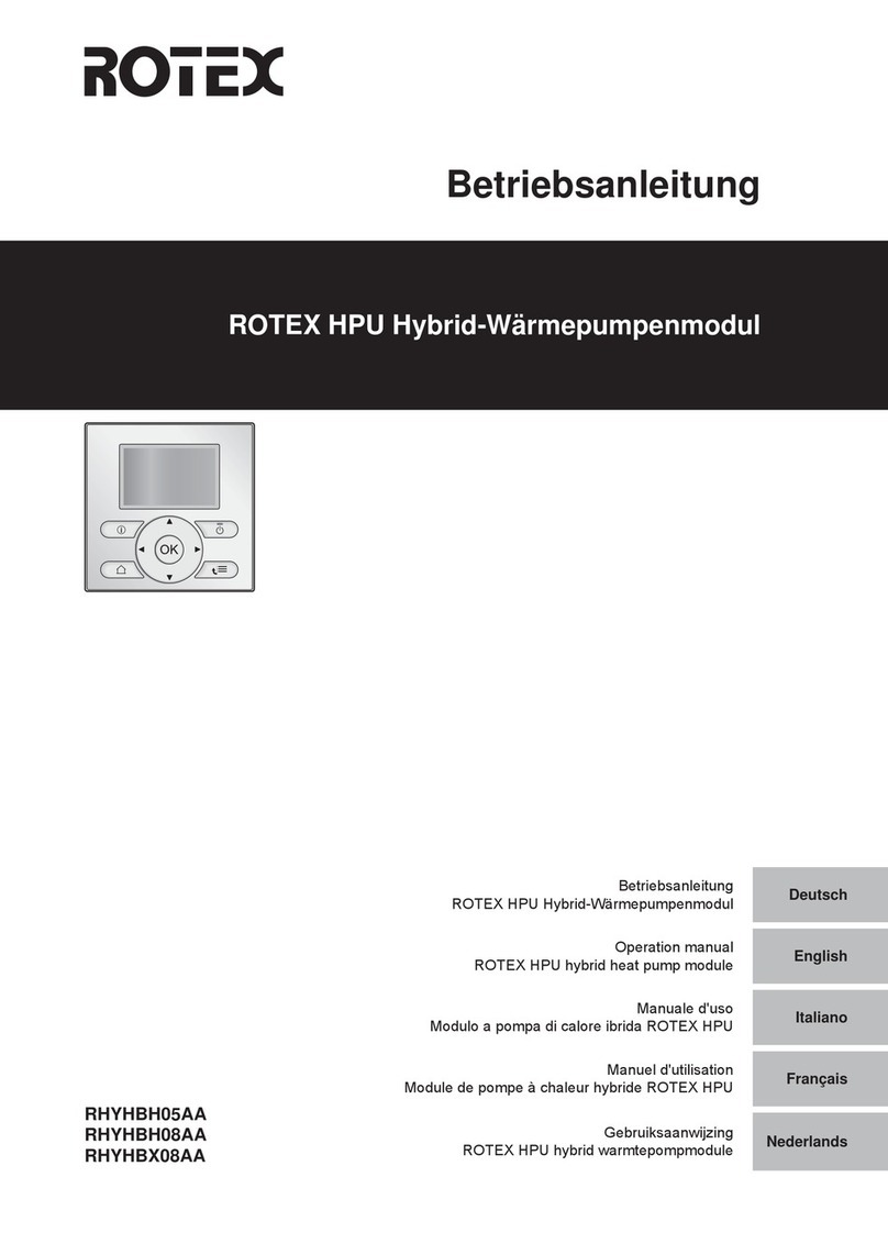
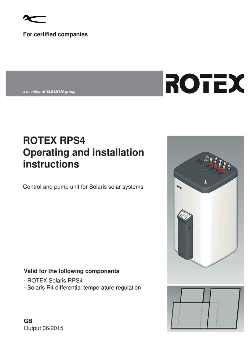
Rotex RoCon mb User manual

For certified companies
ROTEX Control unit
RoCon mb,
RoCon U1,
RoCon M1
Operating instructions
Electronic controller for heat pumps
For ROTEX HPSU monobloc compact types
RKHWMX300C
RKHWMX500C
RKHWMXB300C
RKHWMXB500C
GB
Edition 09/2017

List of contents
2FA ROTEX RoCon mb • 09/2017
1 Safety . . . . . . . . . . . . . . . . . . . . . . . . . . . . . . . 4
1.1 Refer to the manual . . . . . . . . . . . . . . . . . . . . . . . 4
1.2 Warning signs and explanation of symbols . . . . . 4
1.2.1 Meaning of the warnings . . . . . . . . . . . . . . . . . . . . . . 4
1.2.2 Validity. . . . . . . . . . . . . . . . . . . . . . . . . . . . . . . . . . . . 5
1.2.3 Order number . . . . . . . . . . . . . . . . . . . . . . . . . . . . . . 5
1.2.4 Handling instructions. . . . . . . . . . . . . . . . . . . . . . . . . 5
1.3 Avoiding danger . . . . . . . . . . . . . . . . . . . . . . . . . . 5
1.4 Use as intended . . . . . . . . . . . . . . . . . . . . . . . . . . 5
2 Product description. . . . . . . . . . . . . . . . . . . . 6
3 Operation . . . . . . . . . . . . . . . . . . . . . . . . . . . . 7
3.1 General . . . . . . . . . . . . . . . . . . . . . . . . . . . . . . . . 7
3.2.1 Display . . . . . . . . . . . . . . . . . . . . . . . . . . . . . . . . . . . 7
3.2.2 Controls. . . . . . . . . . . . . . . . . . . . . . . . . . . . . . . . . . . 8
3.3 Operating concept . . . . . . . . . . . . . . . . . . . . . . . . 9
3.4 Basic functions and operating modes . . . . . . . . 10
3.4.1 System information (Info) . . . . . . . . . . . . . . . . . . . . 10
3.4.2 Setting the operating mode . . . . . . . . . . . . . . . . . . .12
3.4.3 Temperature setting of daytime room temperature . 14
3.4.4 Temperature setting of setback mode. . . . . . . . . . . 14
3.4.5 Temperature setting of hot water generation . . . . . 14
3.4.6 Unscheduled hot water preparation . . . . . . . . . . . .14
3.4.7 Switching time program. . . . . . . . . . . . . . . . . . . . . . 14
3.4.8 System settings. . . . . . . . . . . . . . . . . . . . . . . . . . . . 17
3.4.9 Terminal function. . . . . . . . . . . . . . . . . . . . . . . . . . . 17
3.4.10 Operation with glycol. . . . . . . . . . . . . . . . . . . . . . . . 18
3.4.11 Whisper mode . . . . . . . . . . . . . . . . . . . . . . . . . . . . . 18
3.4.12 Smart Grid (SG) . . . . . . . . . . . . . . . . . . . . . . . . . . . 19
3.4.13 EHS emergency operation . . . . . . . . . . . . . . . . . . . 19
3.5 Special functions . . . . . . . . . . . . . . . . . . . . . . . . 20
3.5.1 Manual operation . . . . . . . . . . . . . . . . . . . . . . . . . .20
3.5.2 3-way switching valves reference travel. . . . . . . . . 20
3.6 Special system settings . . . . . . . . . . . . . . . . . . . 21
3.6.1 Access rights (technician code) . . . . . . . . . . . . . . . 21
3.6.2 Heat slope. . . . . . . . . . . . . . . . . . . . . . . . . . . . . . . . 21
3.6.3 Cooling slope . . . . . . . . . . . . . . . . . . . . . . . . . . . . .22
3.6.4 Weather-dependent T-HS control . . . . . . . . . . . . . .23
3.6.5 Frost protection function . . . . . . . . . . . . . . . . . . . . . 23
3.6.6 Interlink function . . . . . . . . . . . . . . . . . . . . . . . . . . . 24
3.6.7 Additional alternative heat generator . . . . . . . . . . . 24
3.6.8 Heating support . . . . . . . . . . . . . . . . . . . . . . . . . . . 25
3.6.9 Special function: switching contacts . . . . . . . . . . . . 25
3.6.10 Air purge . . . . . . . . . . . . . . . . . . . . . . . . . . . . . . . . . 25
3.6.11 Anti-legionella system . . . . . . . . . . . . . . . . . . . . . . .26
3.6.12 Resetting to factory settings (reset) . . . . . . . . . . . . 26
3.6.13 Screed program . . . . . . . . . . . . . . . . . . . . . . . . . . .27
3.6.14 Relay test . . . . . . . . . . . . . . . . . . . . . . . . . . . . . . . . 29
3.6.15 Settings for optional circulation pump . . . . . . . . . . . 29
3.6.16 Remote control via Internet . . . . . . . . . . . . . . . . . . . 30
4 Initial start-up. . . . . . . . . . . . . . . . . . . . . . . . 31
4.1 Fundamental aspects of the IDs and
authorisations in the RoCon system . . . . . . . . . 31
4.2 Operating Support during 1st. Commissioning
and during System Extensions . . . . . . . . . . . . . 32
4.3 Commissioning ROTEX
HPSU monobloc compact . . . . . . . . . . . . . . . . . 33
4.3.1 Assigning the terminal ID on the RoCon B1 control
panel of the ROTEX HPSU monobloc compact . . . 33
4.4 Putting optional RoCon system components
into operation . . . . . . . . . . . . . . . . . . . . . . . . . . 33
4.4.1 Mixer module RoCon M1. . . . . . . . . . . . . . . . . . . . .33
4.4.2 RoCon U1 room station. . . . . . . . . . . . . . . . . . . . . .34
4.4.3 Allocating the RoCon M1 mixing module to a heat
generator . . . . . . . . . . . . . . . . . . . . . . . . . . . . . . . . .35
4.4.4 Master RoCon function . . . . . . . . . . . . . . . . . . . . . .35
4.4.5 Caretaker function. . . . . . . . . . . . . . . . . . . . . . . . . .35
5 Parameter overview. . . . . . . . . . . . . . . . . . . 36
5.1 For first commissioning or resetting to factory
settings . . . . . . . . . . . . . . . . . . . . . . . . . . . . . . . 36
5.2 After first commissioning/After successful basic
configuration . . . . . . . . . . . . . . . . . . . . . . . . . . . 37
5.2.1 Rotary switch setting: Configuration . . . . . . . . . . . .37
5.2.2 Rotary switch setting: DHW Install . . . . . . . . . . . . .38
5.2.3 Rotary switch setting: Operating Mode . . . . . . . . .38
5.2.4 Rotary switch setting: Set Temp Day . . . . . . . . . . .38
5.2.5 Rotary switch setting: Set Temp Night . . . . . . . . . .38
5.2.6 Rotary switch setting: DHW Set Temp . . . . . . . . . .38
5.2.7 Rotary switch setting: Time Program . . . . . . . . . . .38
5.2.8 Rotary switch setting: Remote Param . . . . . . . . . .38
5.2.9 Rotary switch setting: Info . . . . . . . . . . . . . . . . . . .38
5.2.10 Exit key: Special function . . . . . . . . . . . . . . . . . . . .38
5.3 Parameter levels for the
RoCon M1 mixer module . . . . . . . . . . . . . . . . . 38
5.3.1 Rotary switch setting: Info . . . . . . . . . . . . . . . . . . .38
5.3.2 Rotary switch setting: Operating Mode . . . . . . . . .38
5.3.3 Rotary switch setting: Set Temp Day . . . . . . . . . . .38
5.3.4 Rotary switch setting: Set Temp Night . . . . . . . . . .38
5.3.5 Rotary switch setting: DHW Set Temp . . . . . . . . . .38
5.3.6 Rotary switch setting: DHW Install . . . . . . . . . . . . .38
5.3.7 Rotary switch setting: Time Program . . . . . . . . . . .39
5.3.8 Rotary switch setting: Remote Param . . . . . . . . . .39
5.3.9 Rotary switch setting: Configuration . . . . . . . . . . . .39
6 Parameter settings . . . . . . . . . . . . . . . . . . . 40
6.1 Explanation of the parameter tables . . . . . . . . . 40
6.2 Rotary switch setting: Configuration . . . . . . . . . 40
6.2.1 "Setup" level . . . . . . . . . . . . . . . . . . . . . . . . . . . . . .40
6.2.2 "System Configuration" level . . . . . . . . . . . . . . . . . .44
6.2.3 "HC Configuration" level . . . . . . . . . . . . . . . . . . . . .45
6.2.4 "DHW Configuration" level . . . . . . . . . . . . . . . . . . .47
6.3 Rotary switch setting: DHW Install . . . . . . . . . . 47
6.4 Rotary switch setting: Operating Mode . . . . . . 48
6.5 Rotary switch setting: Set Temp Day . . . . . . . . 48
6.6 Rotary switch setting: Set Temp Night . . . . . . . 48
6.7 Rotary switch setting: DHW Set Temp . . . . . . . 48
6.8 Rotary switch setting: Time Program . . . . . . . . 49
6.9 Rotary switch setting: Remote Param . . . . . . . 49
6.10 Rotary switch setting: Info . . . . . . . . . . . . . . . . 49
6.11 Exit key: Special function . . . . . . . . . . . . . . . . . 50
6.12 "Basic Configuration" parameter level. . . . . . . . 51
6.13 Parameter levels of the
RoCon M1 mixer module . . . . . . . . . . . . . . . . . 51
6.13.1 Rotary switch setting:
Configuration , "Setup" level . . . . . . . . . . . . . . . . . .52
6.13.2 Rotary switch setting:
Configuration , "Mixer Config" level. . . . . . . . . . . . .53
7 Errors, malfunctions and messages . . . . . 55
7.1 Recognising errors, correcting malfunctions . . . 55
7.1.1 Current error display . . . . . . . . . . . . . . . . . . . . . . . .55
7.1.2 Reading out the protocol . . . . . . . . . . . . . . . . . . . . .55
7.1.3 Troubleshooting. . . . . . . . . . . . . . . . . . . . . . . . . . . .55
List of contents
FA ROTEX RoCon mb • 09/2017 3
7.2 Emergency operation . . . . . . . . . . . . . . . . . . . . .56
7.3 EHS emergency operation . . . . . . . . . . . . . . . . .56
7.4 Malfunctions and fault codes . . . . . . . . . . . . . . .56
8 Glossary. . . . . . . . . . . . . . . . . . . . . . . . . . . . .57
9 Notes . . . . . . . . . . . . . . . . . . . . . . . . . . . . . . .58
9.1 User-specific settings . . . . . . . . . . . . . . . . . . . . .58
9.1.1 Switching time program. . . . . . . . . . . . . . . . . . . . . .58
9.1.2 Parameters . . . . . . . . . . . . . . . . . . . . . . . . . . . . . . .59
9.1.3 IDs in the RoCon CAN bus system . . . . . . . . . . . . .59
9.2 Other items . . . . . . . . . . . . . . . . . . . . . . . . . . . . .60
10 List of keywords . . . . . . . . . . . . . . . . . . . . . .63

4FA ROTEX RoCon mb • 09/2017
1 xSafety
1 Safety
1.1 Refer to the manual
These instructions are the >> translation of the
original version << in your language.
All the activities required for operation and
setting the parameters are described in this in-
struction manual. All parameters needed for
trouble-free operation have been configured at
the factory.
●Please read through this manual carefully
before operating the heating system or before
adjusting the settings for it.
●Make a note of the preset values before you
make any changes to the unit configuration.
Relevant documents
– ROTEX HPSU monobloc compact:
– Installation and maintenance instructions
– Operating instructions for the user/owner
– Commissioning checklist
– the operating manual for the user/owner
– Outdoor unit for ROTEX HPSU monobloc
compact: the respective installation and oper-
ating instructions.
– On connection of a ROTEX solar system: the
respective installation and operating instruc-
tions.
– On connection of a ROTEX HP convector: the
respective installation and operating instruc-
tions.
– For connecting to another ROTEX heat gen-
erator or optional accessories: the associated
installation and operating instructions.
The guides are included in the scope of supply
for the individual units.
1.2 Warning signs and explanation of
symbols
1.2.1 Meaning of the warnings
Warnings in this manual are classified according
into their severity and probability of occurrence.
Special warning signs
Some types of danger are represented by
special symbols:
DANGER!
Draws attention to imminent danger.
Disregarding this warning can lead to serious
injury or death.
WARNING!
Indicates a potentially dangerous situation.
Disregarding this warning may result in serious
physical injury or death.
CAUTION!
Indicates a situation which may cause possible
damage.
Disregarding this warning may cause damage
to property and the environment.
This symbol identifies user tips and par-
ticularly useful information, but not
warnings or hazards.
Electric current
Risk of burning or scalding

1 xSafety
FA ROTEX RoCon mb • 09/2017 5
1.2.2 Validity
Some information in this manual has limited va-
lidity. The validity is highlighted by a symbol.
1.2.3 Order number
Notes related to order numbers are identified by
the shopping cart symbol .
1.2.4 Handling instructions
●Handling instructions are shown as a list.
Actions for which the sequential order must be
maintained are numbered.
Results of actions are identified with an
arrow.
Display readouts of the RoCon controller
Certain screen displays or menu items may de-
viate from those shown in these instructions de-
pending on the national or equipment variant of
the ROTEX HPSU monobloc compact or the
user status logged onto the controller.
1.3 Avoiding danger
The ROTEX HPSU monobloc compact is built
according to the state-of-the-art and the recog-
nised technical rules. However, improper use
may result in serious physical injuries or death,
as well as property damage.
To avoid hazards, only operate the ROTEX
HPSU monobloc compact:
– as stipulated and in perfect condition,
– with an awareness of safety and the hazards
involved.
This assumes knowledge and use of the con-
tents of this manual, of the relevant accident pre-
vention regulations as well as the recognised
safety-related and occupational health rules.
1.4 Use as intended
The RoCon mb controller must only be used in
ROTEX HPSU monobloc compact heat pumps
that are approved for the ROTEX RoCon regu-
lating system. The ROTEX RoCon mb must only
be operated as per the data in these instructions.
Any other use outside the intended use is con-
sidered as improper. The operator alone shall
bear responsibility for any resulting damage.
For any work on the equipment, which extends
above and beyond the operation of the regu-
lating system, you must observe the details pro-
vided in the supplementary documents, particu-
larly with regard to safety instructions.
Only valid for ROTEX HPSU monobloc
compact with cooling function
Only valid/available with a connected
room station (RoCon U1)
Only valid/available with a connected
mixer module (RoCon M1)
Entry into a setting procedure
Exit from a setting procedure
WARNING!
This equipment must only be used by children
aged 8 and above and by persons with re-
stricted physical, sensory or mental capabilities
or with a lack of experience and knowledge, if
they are under supervision or if they have been
instructed in the safe use of the equipment and
understand the dangers arising therefrom.
Children must not play with the equipment.
Cleaning or user maintenance must not be
carried out by children without supervision.

6FA ROTEX RoCon mb • 09/2017
2 xProduct description
2 Product description
Depending on heater unit, the electronic, digital controller auto-
matically regulates all heating, cooling and hot water functions for
a direct heating circuit, a storage tank charging circuit and, via
mixer modules that can be optionally connected, also further
heating circuits.
It undertakes all safety management for the ROTEX HPSU
monobloc compact. This executes a safety switch-off in the event
of a water shortage or undefined operating states. A corre-
sponding error message shows the operator all the information
for fault causes.
All function settings for the ROTEX HPSU monobloc compact
and the optional RoCon devices that are connected via the data
bus are undertaken with the controls of the integrated RoCon B1
control panel and shown on the plain text display with coloured
back-lighting.
The following additional, optional devices can be connected to
the ROTEX HPSU monobloc compact via the controller data bus:
–RoCon U1 room station ( 15 70 34).
–RoCon M1 mixer module ( 15 70 68).
In addition, the RoCon mb controller has a frost protection
function for the direct heating circuit and the storage tank
charging circuit as well as an automatic function for heating
support (integration of an additional heat source such as a wood-
burning boiler or solar system).
The potential-free AUX switching contact can be used to carry out
different control functions in conjunction with external devices
(demand from an external heat generator, switching to bivalent
operating mode, external status display, etc.).
Several inputs for evaluating external control contacts are also
available (external operating mode switching or heat request,
Smart Grid and off-peak EVU functions1).
1) Utility company (EVU) outputs signals that are used to control power grid ca-
pacity utilisation and influence the electricity price and availability.
With the optional RKRSCA1 outside temperature sensor
(14 10 39) that is installed on the north side of the building,
weather-dependent T-HS control can be further optimised.
If the optional RoCon G1 gateway ( 15 70 56) is installed and
connected to the Internet, the ROTEX HPSU monobloc compact
can be conveniently monitored and operated by remote control
using a mobile phone (app).
The RoCon mb control unit contains a timer which can be used
to set:
– 2 individual adjustable switching time programs2) for room
heating and room cooling (direct heating circuit),
– 2 individually-adjustable timer programs for hot water gener-
ation,
– 1 individually-adjustable timer program for an optional circu-
lation pump.
2) Use of the switching time programs for room cooling only in combination with a
connected room thermostat
Initial commissioning of the heating system is described in the in-
stallation instructions for the ROTEX HPSU monobloc compact.
Certain menu items of the RoCon mb control unit are only acces-
sible for the heating expert. This security measure ensures that
no undesirable malfunctions arise during operation of the system
through incorrect settings.
The RoCon U1 room station has the same user interface as the
ROTEX HPSU monobloc compact's integrated RoCon B1 control
panel.
All settings for the allocated heating circuit can be carried out in
the same way as the operating unit. With activated terminal
function, all operating possibilities that are available on the inte-
grated operating unit are available, with the exception of certain
special functions (e.g. Handbetrieb).
After corresponding assignment, a connected RoCon M1 mixer
module is also operated using the RoCon B1 control panel and/or
the RoCon U1 room station.
The RoCon mb controller is part of the ROTEX HPSU
monobloc compact.
It consists of the RoCon BM1 printed circuit board, to
which the actuators, sensors and further components of the
ROTEX RoCon regulating system are connected, and the
RoCon B1 control panel.
In this instruction manual we explain just the functions and
setting possibilities of the control unit. More detailed information
on the ROTEX HPSU monobloc compact and other device com-
ponents can be found in the other applicable documents.

3 xOperation
FA ROTEX RoCon mb • 09/2017 7
3 Operation
3.1 General
3.2 Display and operating elements
3.2.1 Display
All operating steps are supported by corresponding displays on a
coloured backlit plain text display.
The menu guidance can be displayed 7 languages (see
chap. 3.4.8).
The colour of the backlighting indicates the operational status
and the operating mode:
DANGER!
If electrical components come into contact with
water, this can cause an electric shock as well
as cause potentially fatal burns or injuries.
●The displays and the keys of the control unit
must be protected against the effects of
moisture.
●To clean the control unit, use a dry cotton
cloth. Using aggressive cleaning agents
and other fluids can cause damage to
devices or lead to an electric shock.
Maximum energy exploitation
The ROTEX HPSU monobloc compact makes the
most effective use of energy at the lowest possible
return and target hot water temperature.
If an external heat generator (e.g. the optional backup heater)
is activated at target feed temperatures over 50 °C, the effi-
ciency (COP) of the ROTEX HPSU monobloc compact can de-
teriorate (depending on the outside temperature).
1 Clear text display
2 Setting: Configuration
3 Setting: Remote Param
4 Rotary switch
5 Setting: Info
6 Setting: Operating Mode
7 Setting: Set Temp Day
8 Setting: Set Temp Night
9 Setting: DHW Set Temp
10 Rotary button
11 Setting: DHW Install
12 Setting: Time Program
13 Exit key
Fig. 3-1 Arrangement of display and operating elements
Malfunctions are generally indicated by a fault code and
a clear text fault message on the display.
For troubleshooting instructions, see Chapter 7.
White: Standard lighting, normal operating display.
Red: Fault status; depending on the type of fault, the
ROTEX HPSU monobloc compact continues to
operate with restrictions.
Green: Operating mode with operator authorisation.
Blue: Operating mode with expert authorisation.
1 Display date
2 Refrigerant compressor
status
3 Status display (e.g. techni-
cian access rights active)
4 Display time
5 Current feed temperature
6 Heating circuit status
7 Current outside temperature
8 Active operating mode
9 Hot water generation status
10 Current storage temperature
Fig. 3-2 Display of the control unit - standard display

8FA ROTEX RoCon mb • 09/2017
3 xOperation
Explanation of symbols
Tab. 3-1 Explanation of display symbols
3.2.2 Controls
If special key combinations or long key presses are required for
certain functions, these are referred to separately in the re-
spective section of this manual.
Rotary switch
Frequently required functions and setting options can be quickly
and directly selected using the rotary switch (main function level).
Tab. 3-2 Function of the rotary switch
Item
fig. 3-2 Icon Explanation
2Flashing: heat pump request active
Permanently on: refrigerant compressor op-
erating
2No connection to the heat pump outdoor
unit
3Expert access rights active (see
chap. 3.6.1)
2 / 3 Air purge active (see chap. 3.6.10)
2 / 3 Terminal function active (see chap. 3.4.9)
2 / 3 Frost protection function active (see
chap. 3.6.5)
2 / 3 Temporary time program "Party" active (see
chap. 3.4.7)
2 / 3 Temporary time program "Away" active
(see chap. 3.4.7)
2 / 3 Temporary time program "Holiday" active
(see chap. 3.4.7)
2 / 3 Temporary time program "Vacation" active
(see chap. 3.4.7)
2 / 3 Screed program active (see chap. 3.6.13)
5Direct heating circuit
The current feed temperature tV, BH is dis-
played beneath this.
5Mixer circuit
The current T-HS of the assigned heating
circuit is displayed underneath.
5Room temperature sensor
The current room temperature is displayed
underneath.
6Heating circuit status
– Heating circuit active (room heating
function)
– Heating circuit active (room cooling
function)
– Heating circuit not active (currently no
thermal transport in the heating circuit)
7External temperature sensor
The current outside temperature is dis-
played underneath.
8Current operating mode (see chap. 3.4.2)
Standby active
Reducing active
Heating active
Cooling active
Summer active
Automatic 1 active
Automatic 2 active
9Hot water generation active
Hot water generation not active
10 Hot water heating circuit status
The current storage tank temperature tDHW
is displayed beneath this.
CAUTION!
Never operate the operating elements of the
control unit with a hard, pointed object. This can
cause damage and can cause the control to
malfunction.
Irrespective of the rotary switch position, the ROTEX
HPSU monobloc compact operates according to the
operating mode which has been set in the "Operating
Mode" switch position or activated by a special
program.
Action Result
Turning
Direct selection of the main function level
assigned to this switch position.
Item
fig. 3-2 Icon Explanation

3 xOperation
FA ROTEX RoCon mb • 09/2017 9
Rotary button
The rotary button can be used to navigate in the respective level,
to select or change the setting value and to accept this change
with a short key press.
Tab. 3-3 Functions of the rotary button
Exit key
This key can be used to jump back to the previous display within
a menu item or to cancel a function/input.
The special level can also be called up using this key (see
chap. 3.5).
Tab. 3-4 Functions of the Exit key
3.3 Operating concept
The operating concept of the RoCon mb control unit is designed
so that frequently required setting options can be accessed
quickly and directly at the main function level (selection by
means of rotary switch) and less frequently required setting op-
tions are arranged on a lower lying parameter level.
Certain functions and parameters are restricted by access rights
and can only be configured by a heating expert (see chap. 3.6.1).
In normal operation, the rotary switch should be in the po-
sition.
After switching on and successful initialisation, the standard
display automatically shows the display for the rotary switch
setting .
During initial start-up, the setting for the language selection is first
displayed.
●Select the language with the rotary button.
●Confirm the selection with a brief push of the rotary button.
If the system is switched on, the defaults set in the RoCon mb
control unit fully automatically control the operation of the
– room heating, room cooling and
– hot water generation plumbing.
If the user sets a value manually, this setting remains active until
the user changes it or until the timer program forces a different
mode of operation.
Action Result
Turning
To the right (+): increasing adjustment
To the left (–): decreasing adjustment
Touching
Confirm selection, accept setting, execute
function.
Action Result
Touch briefly. – Return to the previous display or the pre-
vious level or
– cancel a special function or an active,
temporary time program.
Press for longer
than 5 seconds.
– A special level is called up.
1 Info (chap. 3.4.1)
2 Operating Mode (chap. 3.4.2)
3 Set Temp Day (chap. 3.4.3)
4 Set Temp Night (chap. 3.4.4)
5 DHW Set Temp (chap. 3.4.5)
6 DHW Install (chap. 3.4.6)
7 Time Program (Chap. 3.4.7)
8 Configuration (Chap. 3.4.8)
9 Remote Param (Chap. 3.4.9)
Fig. 3-3 Illustration of the main function level (rotary switch position)
Adaptations to the special system configuration are
made in the "Configuration" rotary switch setting
(see chap. 3.4.8).
Irrespective of the rotary switch position, the ROTEX
HPSU monobloc compact operates according to the
operating mode which has been set in the "Operating
Mode" switch position or activated by a special
program.

10 FA ROTEX RoCon mb • 09/2017
3 xOperation
The operating modes can be affected by additional functions
such as:
–Weather-dependent T-HS control
–Switching time program
– Setting the temperature target value
– Setting on the room station
– Setting on the room thermostat
– Switch status on the EXT input (external operating mode
changeover)
– Switch status at the EBA input (external requirement request)
– Whisper mode
– Interlink function
– Switch status at the Smart Grid input (EVU function
Smart Grid)
– Switch status at the EVU input (EVU function HT/NT (off-
peak) or Smart Grid)
– Defrost function
– Frost protection function
– Screed function
–Airpurge
– Manual operation
– EHS emergency operation
Keylock
The control panel of the RoCon mb can be locked against inad-
vertent operation (see fig. 3-4).
It is unlocked in the same way.
Precondition for this function is that the [Keylock Function] pa-
rameter at the "Setup" level is set to "On" (see chap. 6.2.1,
tab. 6-1).
3.4 Basic functions and operating modes
Automatic defrost function
At low outdoor temperatures and corresponding humidity, the
heat pump outdoor unit may ice up. This icing impairs efficient op-
eration. The system detects this status automatically and starts
the defrost function.
While the defrost function is active, heat is drawn from the hot
water storage tank, and the backup heater is activated if nec-
essary. Depending on the heat required for the defrost function,
heating the direct heating circuit may be temporarily interrupted
during the defrosting process.
After a maximum of 8 minutes, the system switches back to
normal operation.
3.4.1 System information (Info)
In this rotary switch position, the rotary button can be used to
query all system temperatures, the ROTEX HPSU monobloc
compact type, various software information and the operating
states of all system components in succession. The number of
displayed parameters depends on which components are con-
nected.
No adjustments can be made to these values.
●Set the rotary switch to the "Info" position.
Standard display is shown (see fig. 3-2).
●Press the rotary button briefly.
Parameter overview is displayed.
●Use the rotary button to select the desired information level.
●Confirm the selection with a brief push of the rotary button.
Value is displayed (example, see fig. 3-6).
●Use the rotary button to select the individual information.
Further explanations on, and possible display values for, this rotary switch position
can be found in tab. 3-5 and chap. 6.10.
Fig. 3-4 Activating (1.) and deactivating (4.) the key lock
Keylock Function
On
Keylock Function
Keylock Function
Off
If the storage tank temperature falls below specific
minimum values, the ROTEX HPSU monobloc
compact's safety settings prevent the heat pump from
being operated at low outside temperatures:
–Outside temperature < -2 °C, minimum storage tank
temperature = 30 °C
–Outside temperature < 12 °C, minimum storage tank
temperature = 23 °C.
Without backup heater:
The storage tank water must be heated to the required
minimum storage tank temperature with an external heater
booster.
With backup heater (BUxx):
At an outside temperature of < 12 °C and a storage tank tem-
perature of < 35 °C, the backup heater (BUxx) is automatically
switched on to heat the storage tank water to at least 35 °C.
●To speed up the heating process with backup heater,
temporarily set
– parameter [Function Heating Rod] = "1" and
– parameter [Power DHW] to the maximum value of the
backup heater.
– Set the rotary switch to operating mode, and set the
parameter [1x Hot Water] to "On".

3 xOperation
FA ROTEX RoCon mb • 09/2017 11
Displaying the operating data overview
On the "Overview" information level, the RoCon mb controller's
display shows the current operating data for the ROTEX HPSU
monobloc compact.
The display of the operating data is split over several screen
pages. Adjust the rotary button to navigate between the screen
pages.
Tab. 3-5 Explanation of the operating data displayed as an overview
Short des-
ignation Explanation of the display value
Page 1
Mode Current heat pump mode:
- - -: No heat or cooling request
: Heating
: Cooling
: Hot water generation
: Automatic defrost function active
Ext Current heat pump energy mode:
LT: EVU function HT/NT active and off-peak.
HT: EVU function HT/NT active and peak.
SGN: EVU function Smart Grid active, normal
operation.
SG1: EVU function Smart Grid active, shut-off: no
heat pump operation, no frost protection function.
SG2: EVU function Smart Grid active, switch-on
recommendation, operation at higher target
temperatures, inexpensive electricity.
SG3: EVU function Smart Grid active, switch-on
command and storage tank charging to 70 °C,
inexpensive electricity
- - -: No external mode active, heat pump operates
in standard mode.
RT Parameter [Room thermostat] / [Interlink fct]
= Off: - - -
Parameter [Room thermostat] = On:
–: Heat or cooling request
–: No heat requirement
Parameter [Interlink fct] = On (priority):
– - - -: Frost protection only
– IL1: Normal target feed temperature
–IL2:
– In heating mode, increased target feed
temperature
– In cooling mode, reduced target feed tem-
perature
Pump Current status of the internal heating circulation
pump
VActual flow rate in the heating system
EHS Current output of the backup heater in kW
Page 2
TV Current feed temperature downstream of the plate
heat exchanger (tV1)
TVBH Current heating feed temperature, poss. down-
stream of the heating support heat exchanger
(tV, BH)
TR Current temperature of heating return (tR1)
Tdhw Current temperature in the hot water storage tank
(tDHW)
TA Current outside temperature (measured by the
heat pump outdoor unit temperature sensor)
Psyst Current water-side pressure in the heating system
Page 3
BPV Current position of mixing valve 3UVB1
(100% = A, 0% = B)
3UVD Current position of mixing valve 3UV DHW
(100% = B, 0% = A)
TA2 Current outside temperature (measured by the op-
tional outside temperature sensor RKRSCA1)
Tliq2 Current refrigerant temperature (tL2)
quiet Indicates the whisper mode status
Glycol Glycol present: 0 (No) / 1 (Yes)
Fig. 3-5 Displaying the operating data overview
At low return flow temperatures and with glycol in the
system, only "ffff" is displayed as the volumetric flow, no
current value.
Short des-
ignation Explanation of the display value
On
1205 l/h
3 kW
- - -
- - -
48°C42°C
1°C
1,9 bar36°C
44°C
46°C0%
On
2°C
0%
Mode:
Ext:
RT:
Pump:
V:
EHS:
TV:
TVBH:
TR:
Tdhw:
TA:
Psyst:
BPV:
3UVD:
TA2:
Tliq2:
quiet:
0
Glycol:
Info
Overview
Water Pressure

12 FA ROTEX RoCon mb • 09/2017
3 xOperation
Displaying the water pressure
On the RoCon mb control unit, the system pressure (water
pressure) of the internal circuit (direct heating circuit) can be dis-
played when it is switched on. The water pressure is the first info
parameter available after the operating data overview (see
fig. 3-6).
The permissible water pressure range during operation is de-
pendent on the ROTEX HPSU monobloc compact and the
heating system. The target values and thresholds may only be
set by the heating expert. If the water pressure drops below the
minimum value (set parameter value), it must be increased by
topping up the system (see ROTEX HPSU monobloc compact in-
stallation instructions, chapter entitled "Inspection and mainte-
nance").
3.4.2 Setting the operating mode
The operating mode in which the ROTEX HPSU monobloc com-
pact is to operate is selected using the rotary switch in the "Oper-
ating Mode" position.
The selected operating mode is activated by briefly pressing the
rotary button.
●Set the rotary switch to the "Operating Mode"
position.
An overview is displayed.
●Use the rotary button to select the required operating mode.
●Confirm the selection with a brief push of the rotary button.
ROTEX HPSU monobloc compact operates according to
the set operating mode.
The current operating mode is indicated by an appropriate
symbol on the standard display.
Operating mode Standby (Stand-by)
The pressure limits for safety shut-off and the target
pressure can be set in the parameter setting on the
"System Configuration" level.
Fig. 3-6 Displaying info values (e.g. system pressure)
Info
Overview
Water Pressure
T-HS
Water Pressure
Fig. 3-7 Changing the operating mode
(e.g. from "Standby" to "Automatic 1")
CAUTION!
A heating system that is not protected against
frost can freeze in the event of frost and thus be
damaged.
●Add glycol to the heating water circuit (see
installation and maintenance instructions)
●Alternatively, drain the heating system on the
water side if there is a danger of frost.
●If the heating system is not drained, the
power supply must be ensured and the
external main switch must remain switched
on if there is a danger of frost.
Operating Mode
Standby
Reducing
Operating Mode
Heating
Cooling
Summer
Operating Mode
Summer
Automatic 1
Automatic 2
Operating Mode
Summer
Automatic 1
Automatic 2

3 xOperation
FA ROTEX RoCon mb • 09/2017 13
In this operating mode, the ROTEX HPSU monobloc compact is
switched to Stand-by mode. The frost protection function (see
chap. 3.6.5) is maintained. In order to maintain this function, the
system may not be disconnected from the mains.
All controllers integrated in the RoCon system via the CAN bus
are primarily also switched to the "Standby" operating mode.
Operating mode Reducing
Reduced heating mode (lower target room temperature) ac-
cording to the target feed temperature set for reducing mode in
the parameter [T-Reduced] (see chap. 3.4.4).
Hot water preparation according to the set target hot water tem-
peratures and switching cycles in the hot water time program
[DHW Program 1] (see chap. 3.4.5).
Operating modes Heating, Cooling
Heating, cooling mode according to the target room temperature
set in the parameter [T-Room 1 Setpoint] (see chap. 3.4.3).
A connected outside temperature sensor (weather-dependent T-
HS control) or a connected room station also influence the target
feed temperature (prerequisite: parameter [HC Function] = On).
Hot water preparation according to the set target hot water tem-
peratures and switching cycles in the hot water time program
[DHW Program 1] (see chap. 3.4.5).
Operating mode Summer
Hot water preparation according to the set target hot water tem-
peratures and switching cycles in the hot water time program
[DHW Program 1] (see chap. 3.4.5).
All controllers integrated in the RoCon system via the CAN bus
are primarily also switched to the "Summer" operating mode.
Operating mode Automatic 1 (time program)
Automatic heating and setback mode according to the permanent
time programs (see chap. 3.4.7):
– [HC Program 1]
– [DHW Program 1]
Operating mode Automatic 2 (time program)
Automatic heating and setback mode according to the permanent
time programs (see chap. 3.4.7):
– [HC Program 2]
– [DHW Program 2]
Tab. 3-6 Resistance values for evaluating the EXT signal
Besides these operating modes, different temporary heating pro-
grams (see tab. 3-7) are available that are carried out with priority
after activation.
* only with technician code.
Tab. 3-7 Overview of temporary time programs
Fig. 3-8 Standard display in the "Standby" operating mode
(above the frost limit temperature)
If the hot water readiness is in setback mode in the
active operating mode, a temporary "DHW Re-
heating" can be set with the rotary switch setting
without having to change other standard settings (see
chap. 3.4.6).
Switching contact for external operating mode
switch-over
A potential-free switching contact connected via
ROTEX HPSU monobloc compact connection J8 at the "EXT"
terminals and wired with a resistor can also be used to switch
the operating mode from an external device (e.g. modem, …).
In this case, the switching contact functionality is dependent on
the parameter [Function BSC]:
– [Function BSC] = 0 (default setting): evaluation of the resist-
ance values (see tab. 3-6)
– [Function BSC] = 1: evaluation as a burner blocking contact.
If the switching contact is closed, the external heat generator
has priority.
Operating mode Resistance Tolerance
Standby < 680 Ω
± 5 %
Heating 1200 Ω
Reducing 1800 Ω
Summer 2700 Ω
Automatic 1 4700 Ω
Automatic 2 8200 Ω
The resistances specified in tab. 3-6 function in a toler-
ance field of 5%. Resistances outside this tolerance
field are interpreted as an open input. The heat gener-
ator switches back to the previously active operating
mode.
The input is not considered for resistance values greater than
the value for "Automatic 2".
If several switching contacts are to be connected to the ROTEX
HPSU monobloc compact (e.g. Smart Grid, room thermostat),
the related functions may have a higher priority than external op-
erating mode switch-over. The operating mode requested by the
EXT switching contact is then possibly not activated, or is only
activated later.
Temporary
time program Setting/Activa-
tion in the level Rotaryswitch
setting Information
DHW Install DHW Install Chap. 3.4.6
Party
Time Program
Chap. 3.4.7
Away
Holiday
Vacation
Screed*
Configuration >
HC Configura-
tion
Chap. 3.6.13
If a temporary time program (DHW Install, Party, Away,
Holiday, Vacation, Screed) is started during the se-
lected operating mode, control is carried out primarily
according to the settings for this time program.

14 FA ROTEX RoCon mb • 09/2017
3 xOperation
3.4.3 Temperature setting of daytime room
temperature
In rotary switch position , the target room temperatures during
the day for room heating are defined.
●Set the rotary switch to the "Set Temp Day" position.
An overview is displayed.
●Select the temperature block to be set with the rotary button.
●Confirm the selection with a brief push of the rotary button.
Settings are displayed.
●Set the temperature.
●Confirm the selection with a brief push of the rotary button.
Change has been accepted. Jump back to previous dis-
play.
Detailed explanations and possible setting values for this rotary switch setting can
be found in chap. 6.5.
3.4.4 Temperature setting of setback mode
In rotary switch position , the target room temperatures in re-
ducing mode for room heating are defined.
●Set the rotary switch to the "Set Temp Night" position.
An overview is displayed.
●Select the parameter to be set with the rotary button.
●Confirm the selection with a brief push of the rotary button.
– [T-Reduced]: Setting value for "Reducing" operating
mode or reduction through permanent time program.
– [T-Absence]: Setting value for temporary heating/cooling
programs ("Away" and "Vacation").
Settings are displayed.
●Set the temperature.
●Confirm the selection with a brief push of the rotary button.
Change has been accepted. Jump back to previous dis-
play.
Detailed explanations and possible setting values for this rotary switch setting can
be found in chap. 6.6.
3.4.5 Temperature setting of hot water generation
In rotary switch position , the target hot water temperatures
for hot water preparation for the respective time programs are de-
fined.
●Set the rotary switch to the "DHW Set Temp" position.
●Select the temperature block to be set with the rotary button.
●Confirm the selection with a brief push of the rotary button.
Settings are displayed.
●Set the temperature.
●Confirm the selection with a brief push of the rotary button.
Change has been accepted. Jump back to previous dis-
play.
Detailed explanations and possible setting values for this rotary switch setting can
be found in chap. 6.7.
3.4.6 Unscheduled hot water preparation
In rotary switch position the hot water can be recharged
manually, outside of a hot water time program, to the target tem-
perature set as default in the parameter [T-DHW Setpoint 1]. The
heating up is carried out with priority and independent of other
heating programs.
●Set the rotary switch to the "DHW Install" position.
An overview is displayed.
●Select the parameter to be set with the rotary button.
– [1x Hot Water]: Activation of one-time hot water genera-
tion.
●Confirm the selection with a brief push of the rotary button.
●Set the parameter.
●Confirm the selection with a brief push of the rotary button.
The unscheduled hot water generation starts.
Detailed explanations and possible setting values for this rotary switch setting can
be found in chap. 6.3.
3.4.7 Switching time program
For comfortable and individual room and hot water temperature
control, different (but freely adjustable) time programs preset at
the factory can be selected.
The switching time programs control the assigned heating circuit,
the storage charging circuit as well as an optionally connected
circulation pump according to the specified switching times.
Setting
In the rotary switch setting, the time intervals for the
heating circuit, integrated hot water generation and the optional
circulation pump are set.
●Set the rotary switch to the "Time Program"
position.
An overview is displayed.
●Use the rotary button to select the time program to be set.
●Confirm the selection with a brief push of the rotary button.
Settings are displayed.
●Use the rotary button to select and change the value to be
adjusted.
●Confirm the selection with a brief push of the rotary button.
More detailed explanations and possible setting values for this rotary switch position
can be found in chap. 6.8.
The last digits of the parameter designations (1 - 3)
within this rotary switch setting mark the affiliation to
the respective cycle of the time program.
The last digits of the parameter designations (1 - 3)
within this rotary switch setting mark the affiliation to
the respective cycle of the time program.
After this temporary function has elapsed, the control
unit automatically jumps back to the previously active
operating mode. The rotary switch should therefore be
brought back into the "Info" position after the
function has been activated.
The function is subject to time limitations.
At the latest, it is cancelled after the maximum loading time set
in the parameter [Max DHW loading time], and can be restarted
at the earliest after the blocking time set in the parameter [DHW
Off Time] has expired (see chap. 6.2.4).

3 xOperation
FA ROTEX RoCon mb • 09/2017 15
Permanent time programs
Time programs control the heating circuit temperatures or the op-
erating times of the circulation pump according to the specified
switching cycles for the connected heating circuits and the
storage charging circuit. The switching cycles are saved in time
blocks for which different target temperatures can be set.
In the switching cycles, the heating system is controlled differ-
ently according to day and reducing mode.
The target temperatures for these time programs are set in the
rotary switch positions "Set Temp Day" , "Set Temp Night"
and "DHW Set Temp" .
The following switching time programs are available:
–2 time programs for the heating circuit, each with 3 possi-
ble switching cycles
– [HC Program 1]
– [HC Program 2]
Tab. 3-8 Menu structure of heating circuit/time program
–2 time programs for the hot water circuit, each with 3 pos-
sible switching cycles
– [DHW Program 1]
– [DHW Program 2]
–1 time program for an optionally connected circulation
pump, each with 3 possible switching cycles
– [Circulation Time]
Saved switching time programs can be changed at any time. For
a better overview, it is recommended to write down and safely
store the programmed switching cycles (see chap. 9.1.1).
The permanent time programs are preset according to tab. 3-9.
The times can be entered separately for each individual
weekday or in blocks of "Monday to Friday", "Saturday
to Sunday" and "Monday to Sunday".
Program Time period Switching cycle
HC Program 1 Individual weekday
(Monday, Tuesday …)
1.
2.
3.
06:00 -> 22:00
--:-- -> --:--
--:-- -> --:--
Working week
(Monday to Friday)
1.
2.
3.
06:00 -> 22:00
--:-- -> --:--
--:-- -> --:--
Weekend
(Saturday to Sunday)
1.
2.
3.
07:00 -> 23:00
--:-- -> --:--
--:-- -> --:--
Whole week
(Monday to Sunday)
1.
2.
3.
06:00 -> 22:00
--:-- -> --:--
--:-- -> --:--
HC Program 2 See
HC Program 1
1.
2.
3.
See
HC Program 1
Time settings for a switching cycle in a weekday or
block program will also be accepted for other time pe-
riods as long as they are for the same weekdays. Ex-
amples referring to tab. 3-8:
a) The starting time in the 1st switching cycle is changed from
06:00 am to 05:00 am for the individual weekday "Monday".
The 1st switching cycle is also automatically changed
from 06:00 am to 05:00 am for the "working week" and
"whole week" time periods.
b) The starting time in the 1st switching cycle is changed from
07:00 am to 08:00 am for the "weekend" time period.
The 1st switching cycle is also automatically changed
from 07:00 am to 08:00 am for the individual weekdays
"Saturday" and "Sunday".
c) The end time in the 1st switching cycle is changed from
10:00 pm to 9:30 pm for the "whole week" time period.
The 1st switching cycle is also automatically changed
from 10:00 pm to 9:30 pm in all weekday or block pro-
grams.
The setting and the entry structure of the time programs
are identical with those for the heating circuit time
program (see also tab. 3-8).
The setting and the entry structure of the time program
are identical with those for the heating circuit time pro-
gram (see also tab. 3-8).
For further information on settings for an optional circulation
pump, see chap. 3.6.15.

16 FA ROTEX RoCon mb • 09/2017
3 xOperation
Tab. 3-9 Factory setting of the permanent switching time programs
Temporary time programs
4 temporary time programs are available for special situations,
which make the permanent time programs or the currently set
operating mode ineffective for the duration of their validity.
The symbol of the temporary time program is displayed in the
header of the standard display for as long as the time program is
active.
1. [Party]: Immediate one-off extension of room heating.
a) If an automatic program is activated, the last valid
switching cycle is always extended. In the time prior to
switching cycle 1, control is carried out according to the
target room temperature set in the parameter [T-Room 1
Setpoint].
b) In all other operating modes, control is carried out accord-
ing to the target room temperature set in the parameter [T-
Room 1 Setpoint].
– The hot water generation is not affected.
– The time program runs for the set time period from activa-
tion.
2. [Away]: Immediate one-time setback up to 6 hours.
– In reducing mode, control is carried out according to the
target room temperature set in the "Set Temp Night"
rotary switch position in the parameter [T-Absence].
– The hot water generation is not affected.
– The time program runs for the set time period from activa-
tion.
3. [Holiday]: One-time calendar-controlled presence.
– Control is carried out only according to the settings for
"Sunday" in the [HC Program 1].
– The hot water generation is only controlled according to
the settings for "Sunday" in the [DHW Program 1].
4. [Vacation]: One-time calendar-controlled setback.
– In reducing mode, control is carried out exclusively
according to the target room temperature set in the "Set
Temp Night" rotary switch position in the parameter
[T-Absence].
– Hot water generation according to the set target tempera-
tures and switching cycles in the [DHW Program 1] hot
water time program (see chap. 3.4.5).
– The calendar-controlled [Vacation] program is not
started if the "Standby" or "Manual Operation" operating
mode is active on the set start date.
Switching cycle 1 Switching cycle 2 Switching cycle 3
Time period On Off On Off On Off
Room heating / room cooling
Temperature setting [T-Room 1 Setpoint]: 20 °C [T-Room 2 Setpoint]: 20 °C [T-Room 3 Setpoint]: 20 °C
[T-Reduced]: 10 °C
"HC Program 1"
Monday - Friday 06:00 22:00 - - : - - - - : - - - - : - - - - : - -
Saturday, Sunday 07:00 23:00 - - : - - - - : - - - - : - - - - : - -
"HC Program 2"
Monday - Friday 06:00 08:00 - - : - - - - : - - - - : - - - - : - -
Saturday, Sunday 07:00 23:00 - - : - - - - : - - - - : - - - - : - -
Domestic hot water generation
Temperature setting [T-DHW Setpoint 1]: 48 °C [T-DHW Setpoint 2]: 48 °C [T-DHW Setpoint 3]: 48 °C
"DHW Program 1"
Monday - Sunday 00:00 24:00 - - : - - - - : - - - - : - - - - : - -
"DHW Program 2"
Monday - Friday 05:00 21:00 - - : - - - - : - - - - : - - - - : - -
Saturday, Sunday 06:00 22:00 - - : - - - - : - - - - : - - - - : - -
"Circulation Time"
Monday - Friday 05:00 21:00 - - : - - - - : - - - - : - - - - : - -
Saturday, Sunday 06:00 22:00 - - : - - - - : - - - - : - - - - : - -
The following temporary time programs can be can-
celled at any time due to the manual changing of the
operating mode.

3 xOperation
FA ROTEX RoCon mb • 09/2017 17
3.4.8 System settings
In the "Configuration" rotary switch position, basic setting
of the RoCon mb controller and system configuration for the
installation environment of the ROTEX HPSU monobloc com-
pact, the direct heating circuit, hot water preparation and any
optionally connected components are carried out.
Depending on the access authorisation (user or expert), different
parameters are available. Several parameters can only be ac-
cessed by the heating expert.
Setting the LCD display, language, date, time
●Set the rotary switch to the "Configuration" position.
An overview is displayed.
●Use the rotary button to select the "Setup" level.
An overview is displayed.
●With the rotary button, select the parameters [LCD
Brightness] and [LCD Illum Time], and change them if
desired.
●With the rotary button, select and confirm the parameters
[Language], [Date] or [Time].
●Use the rotary button to select and change the value to be
changed within the respective display.
●Confirm the selection with a brief push of the rotary button.
Change has been accepted. Jump back to previous dis-
play.
Detailed explanations and possible setting values of this rotary switch setting can be
found in chap. 3.6 and in chap. 6.2.
3.4.9 Terminal function
In the "Remote Param" rotary switch setting, other devices
(mixer module control unit or heat generator control components)
integrated in the RoCon system via the CAN bus can also be op-
erated and parametrised as long as the respective control unit
has the required authorisation (see also chap. 4.3).
The local control unit functions as a remote control for the ex-
ternal device. In this case, all the control functions are performed
and saved 1:1 as on the external device.
The different application and parametrisation options for the use
of the devices and control units in the RoCon system connected
via the CAN bus are described in chap. 4.3.
An internally pre-programmed calendar ensures an au-
tomatic timeshift for the annually repeating sum-
mertime/wintertime changeover dates.
A list of the recognised devices
is displayed for selection on the
display after activation of the
"Bus - Scan" (external devices
and local device).
After selection and confir-
mation of an external device,
the terminal function for this
device is activated and the as-
sociated standard display for
this device is shown on the
display.
The operating component is
then in terminal operation.
Fig. 3-9 Display of the "Remote
Param" level during
commissioning or after
interim disconnection
from the mains
Remote Param
Bus - Scan
No selection
B1 RoCon B1 control panel of the HPSU monobloc compact
Bus CAN bus (connection line between RoCon devices
and control units)
H1Direct heating circuit (e.g. radiators)
H2Mixed heating circuit (e.g. floor heating)
M1 RoCon M1 mixer module
U1 RoCon U1 room station
WE1 Heat generator HPSU monobloc compact
Fig. 3-10 Example of "Bus - Scan" on a heating system with 1 heat gen-
erator, 1 mix valve, 1 room station and activation of the termi-
nal function for remote control of the mixer module
Remote Param
Bus - Scan
No selection
Remote Param
Bus - Scan
No selection
Remote Param
No selection
Contr BM1/BE1 #X
Mix Valve #X
Remote Param
Contr BM1/BE1 #X
Mix Valve #X
Remote Param
Contr BM1/BE1 #X
Mix Valve #X

18 FA ROTEX RoCon mb • 09/2017
3 xOperation
If the terminal function is activated, the #X symbol is dis-
played in the header of the display as additional information on
the remote-controlled device, where "X" is the set device identifi-
cation of the remote-controlled device.
The displayed values and symbols are always accepted by the
selected device (e.g. mixer circuit T-HS of the RoCon M1 mix
valve module with device identification 1).
In order to operate the local device, it must be activated again in
the selection list ([No selection] parameter).
Activating/deactivating terminal operation
Prerequisite: a valid terminal ID has been assigned to the
RoCon B1 control panel of the ROTEX HPSU monobloc compact
or the RoCon U1 room station ( 15 70 34).
●Set the rotary switch to the "Remote Param" position.
The "Remote Param" level is displayed.
●Use the rotary button to select the [Bus - Scan] parameter.
●Confirm the selection with a brief push of the rotary button.
The context menu is displayed.
●Use the rotary button to select the [Bus - Scan] parameter and
confirm with "Yes".
Bus - Scan is performed.
An overview of all the devices found is displayed (for an
example, see fig. 3-10).
●Use the rotary button to select the device for which the
terminal function should be carried out.
●Confirm the selection with a brief push of the rotary button.
The local control unit functions as a remote control for the
external device.
To end terminal operation and to switch back to the control unit
for the operation of the assigned device, the [No selection] pa-
rameter must be selected and confirmed at the "Remote
Param" level.
3.4.10 Operation with glycol
Frost can damage the system. To prevent the hydraulic compo-
nents from freezing, the software is equipped with special frost
protection functions, that include the activation of pump, internal
heaters, and/or backup heater operation in case of low tempera-
tures.
However, in case of a power failure, these functions cannot guar-
antee protection. It is therefore recommended to add glycol to the
water circuit. To do this, observe the installation and mainte-
nance instructions.
If glycol has been added to the system, the RoCon controller
setting must be adapted accordingly.
●Set the rotary switch to the "Configuration" position.
An overview is displayed.
●Use the rotary button to select the "Setup" level.
An overview is displayed.
●Use the rotary button to select the [Glycol] parameter.
●Change the parameter if desired.
– Parameter [Glycol] = 0: no glycol added
– Parameter [Glycol] = 1: glycol added
●Confirm the selection with a brief push of the rotary button.
Change has been accepted. Jump back to previous dis-
play.
3.4.11 Whisper mode
Whisper mode means that the heat pump outdoor unit operates
at reduced output. This reduces the operating noise generated by
the heat pump outdoor unit.
Activating / deactivating whisper mode
●Set the rotary switch to the "Configuration" position.
An overview is displayed.
●Use the rotary button to select the "System Configuration"
level.
An overview is displayed.
Fig. 3-11 Example of the display for the remote-controlled mixer module
If the "n.A." message is displayed in the rotary switch
setting , no valid terminal ID has been assigned to
the control unit until now.
If the "n.A." message is still displayed, it may be necessary to
update the device software in order to use the terminal function.
Contact the ROTEX Service Team for this.
For setting the terminal ID of optionally connected
devices, see chap. 4.4 or the respective operating
instructions that are supplied.
After an interim disconnection from the power supply,
the display always appears at the "Remote Param"
level, as shown in fig. 3-9.
To be able to use the terminal function for connected devices, a
repeat Bus - Scan must be carried out.
Communication between the RoCon system components also
continues to function without a Bus - Scan, and previously un-
dertaken settings remain active.
The terminal function is activated as shown in fig. 3-10, but after
confirmation of the "Bus - Scan" display, the [New scan?] pa-
rameter must be selected with the rotary button and confirmed
with "Yes".
CAUTION!
During active whisper mode, the output in room
heating and room cooling mode decreases such
that it may no longer be possible to achieve pre-
set target temperature values.
●With outside temperatures below freezing,
there is a risk of material damage caused by
frost.

3 xOperation
FA ROTEX RoCon mb • 09/2017 19
●Use the rotary button to select the [Quite Mode] parameter.
●Confirm the selection with a brief push of the rotary button.
The setting of the parameter is displayed.
●Set the parameter.
– Parameter [Quite Mode] = 0: deactivated
– Parameter [Quite Mode] = 1: permanently activated
– Parameter [Quite Mode] = 2: only activated at night
●Confirm the selection with a brief push of the rotary button.
Change has been accepted. Jump back to previous dis-
play.
Detailed explanations and possible setting values of this function can be found in
chap. 6.2.2.
3.4.12 Smart Grid (SG)
A special electricity meter with SG receiver, to which the ROTEX
HPSU monobloc compact must be connected, is required to use
this function.
As soon as the function is activated by the parameter [SMART
GRID] = 1, the heat pump is set to an operating mode as per
tab. 3-10 depending on the utility company signal.
1) No frost protection function (see chap. 3.6.5).
2) Switching contacts at input J8 of the RoCon BM1 printed circuit board closed
(1) or opened (0).
Tab. 3-10 Use of the SG signal
Detailed explanations and possible setting values of this function can be found in
chap. 6.2.1.
3.4.13 EHS emergency operation
If the heat pump fails, the backup heater can be used as emer-
gency heating, and can undertake all heating requirements either
automatically or non-automatically.
Activating / deactivating emergency automatic
operation
●Set the rotary switch to the "Configuration" position.
An overview is displayed.
●Use the rotary button to select the "Setup" level.
An overview is displayed.
●Use the rotary button to select the [Emergency BUH]
parameter.
●Confirm the selection with a brief push of the rotary button.
The setting of the parameter is displayed.
●Set the parameter.
– Parameter [Emergency BUH] = 0: no automatic emer-
gency operation
– Parameter [Emergency BUH] = 1: automatic emergency
operation
●Confirm the selection with a brief push of the rotary button.
Change has been accepted. Jump back to previous dis-
play.
WARNING!
There is a danger of scalding at target hot water
temperatures over 60 °C. This is possible, as
the utility company (EVU) is entitled to control
current draw optimised according to supply and
demand in the definitions for Smart Grid.
Due to such forced charging, the target hot
water temperature in the hot water storage tank
can exceed 60 °C.
This storage tank charging is carried out even
when "Standby" operating mode is set.
●Install scald protection in the hot water distri-
bution line (e.g. VTA32, 15 60 15 + Screw
set 1", 15 60 16).
Signal2) Electric-
ity costs Effect on
EVU SG Domestic hot
water Heating installa-
tions
1 0 - - - No operation1) No operation1)
0 0 Normal Normal operation Normal operation
0 1 Low Switch-on recom-
mendation, and tar-
get storage tank
temperature value is
increased depending
on the parameter
[Mode SG]
Switch-on recom-
mendation, and tar-
get feed temperature
is increased depend-
ing on the parameter
[Mode SG]
1 1 Very low Switch-on command,
and target storage
tank temperature val-
ue is set to 70 °C
Switch-on command
for storage tank
charging
Activation of emergency automatic operation ensures
that heating and hot water requirements are reliably
met even if the heat pump fails. However, the risk is run
that the user only notices the system malfunction after
a certain time, and that electricity consumption is thus in-
creased.
If emergency automatic operation is deactivated (default
setting), it must be activated as described below to meet heating
and hot water requirements in the event that the outdoor unit
fails.

20 FA ROTEX RoCon mb • 09/2017
3 xOperation
3.5 Special functions
At the "Special Level", different functions (mostly useful func-
tions for the heating expert) can be carried out.
The following special functions are possible:
– Manual operation (see chap. 3.5.1).
– Displaying messages (see chapter 7)
– Reset to factory settings (see chap. 3.6.12)
Detailed explanations of these functions can be found in chap. 6.11.
●Push the Exit button for at least 5 s.
Menu "Special Level" is displayed.
●Use the rotary button to select the program to be started.
●Confirm the selection with a brief push of the rotary button.
The selected program starts.
●Cancellation and jump back by:
– pressing the Exit key again or
– touching the rotary button or
– selecting another menu using the rotary switch.
3.5.1 Manual operation
Manual operation is used to manually control the ROTEX HPSU
monobloc compact to a specific feed temperature. Manual oper-
ation should only be used for diagnostic purposes.
With hydraulically controlled priority operation for hot water prep-
aration, it must be ensured that the target feed temperature set in
manual mode is sufficient to achieve the stored target hot water
temperature (parameter [T-DHW Setpoint 1]).
●Push the Exit button for at least 5 s.
Menu "Special Level" is displayed.
●Use the rotary button to select the "Manual Operation"
program.
●Confirm the selection with a brief push of the rotary button.
"Manual Operation" is active.
●Use the rotary button to set the target feed temperature.
During active manual mode, the storage tank temperature
is permanently regulated to the first target hot water tem-
perature parameter value ([T-DHW Setpoint 1]).
The key lock (if it was activated prior to the start of this
function) is reactivated within 2 s to prevent undesired
cancellation of the function through operation of the
RoCon mb controller.
●Cancellation and jump back by:
– pressing the Exit key again or
– touching the rotary button or
– selecting another menu using the rotary switch.
If manual operation is ended, the RoCon mb control unit
automatically switches to "Standby" operating mode.
3.5.2 3-way switching valves reference travel
The positions of the two 3-way switch valves 3UVB1 and 3UV
DHW in the ROTEX HPSU monobloc compact are controlled
continuously between their two basic settings for optimised
energy utilisation (e.g. heating support function).
To ensure this function, the two 3-way switch valves are always
moved automatically to their basic position (bypass - path AB-A
open) at 11:00 hours.
This function can take up to 5 minutes. It is programmed as
standard and cannot be changed.
The calling-up of the special functions does not depend
on the rotary switch setting.
Do not confirm this setting with the rotary button,
as the program is otherwise ended.
Fig. 3-12 Symbolic brief instructions for manual operation
Manual Operation
Special Level
Attention!
Actual mode:
Special Level
Manual Operation
FA failure
Set Point Current Value
This manual suits for next models
2
Table of contents
Other Rotex Control Unit manuals

Rotex
Rotex 30138 Installation and operation manual

Rotex
Rotex RPS4 User manual

Rotex
Rotex E PAC Series User manual

Rotex
Rotex 31123 Service manual

Rotex
Rotex 30308 Assembly instructions

Rotex
Rotex 51424 Service manual

Rotex
Rotex RoCon U1 User manual

Rotex
Rotex 24201 User manual

Rotex
Rotex RHYHBH05AA User manual
Popular Control Unit manuals by other brands

Lutron Electronics
Lutron Electronics PowPak RMJ-CCO1-24-B Installation

Philips
Philips Strand Lighting Operation guide

Dataprobe
Dataprobe iBootBar Installation and operations

Xsens
Xsens MTi 600 Series Hardware Integration Manual

Fisher
Fisher D4 instruction manual

GE
GE Baker Hughes Masoneilan 31000 Series instruction manual