Roth Touchline Product information sheet

Roth Touchline
Quick and easy user manual
German quality since 1947
1/10

2/10
Touchline, quick guide
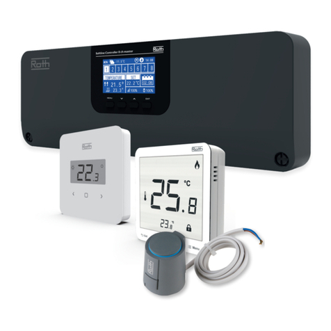
The Roth Touchline underoor heating system consists of 1 - 5
control devices and a number of room thermostats.
The control device can operate functions such as pump stop/start,
boiler enable signal, actuator motioning and cooling regulation
from heat pumps.
NB! All of the Touchline controller terminal outputs are designed
as 24V or 230V potential relay switches.
The Touchline system will therefor work as an switch/distributor
for external components, when voltage is added to the terminal
outputs.
1. Summary: control device
1. Transformer 230V to 24V AC.
2. Wireless control device.
3. The LED illuminates when heating is required and
ashes during pairing and connecting.
4. Use pushbuttons for pairing and connecting.
5. Terminals/outputs.
6. Stress relief for wiring.
7. Micro SD card reader for rmware updates.
8. External antenna input.
9. LAN cable input (optional).
2a. Summary: Touchline thermostat
1. Wireless system connection symbol (ON).
2. Temperature setpoint and actual temperature value, time
setting, week program and oor temperature setting on display.
3. Arrow tabs for time and date setting and other value changes.
4. New multi function tab.
5. Menu tab, mode and parameter selection.
6. Back tab.
7. OK tab.
8. Opening: To open the wireless room thermostat, use a 5 mm
Phillips screwdriver.
9. IR sensor (IR model only).
2b. Summary: Touchline display
10. Battery alarm, eco-indicator, dew point, general alarm and lock.
11. Days of the week for time schedule settings.
12. Room/oor temperature.
13. Help text for conguration.
14. Modes and setting.
1
2a
2b
789
1
CH 1CH 3
24V 24V
CH 2
24V 24V 24V 24V
25 26 27 28 29 30 31 32 35 3633 34
3
4
5
6
2
03 11
01 12
02 13 14 15 16 17 20
230 V 24 V
Trafo
Pump
230 V
in
eco
24 V %H
c/o in
out
0604 05
c/o out
0807 18 19
1009
c/o in
230 V
/TB
NL
NNL L
CH 4
°C 2
3
4
1
5
7
6
IR
8
89
°C
164 52 3 7
%
RESET TIMEDATETEMP SERV
10
12
11
13
14
The thermostats are available with and without oor sensors (IR).
The Roth Touchline system is easy to use and can be controlled
with an Android or iOS app. The most commonly used settings are
listed below.
If you need the complete user manual, this is available to down-
load at www.roth-uk.com
Content:
Quick start (Installer)
› User settings (user)
Extended settings (Installer)

3/10
3. Install the Touchline control device and connect the actuators (24V).
1
2
3
min. 33
4
4
click
3
Touchline
41
IR
3
2
a
b
click
~1. 5 m
4. Insert the batteries in the thermostats and mount the thermostats on the wall.
A: Applicable to all thermostats.
B: Applicable to IR thermostats only.
4
4a
~1. 5 m
~1. 5 m
0.12 m
0.555 m 0.555 m
4b

4/10
5. Pump and boiler wiring diagrams, for the 24v
Touchline controller.
Image 5.a Pump connection diagram
Main, 230V Input on terminals 1, 3, 5 and Pump output
supply from terminals 2, 4, 6 on the Touchline controller.
(Functioning as an On/O switch when heating is required
from the Touchline thermostat).
Image 5.b Boiler connection diagram
Main, 230V Input blue wire on terminal 7, and Boiler
output supply blue wire from terminal 8, on the Touchline
controller.
(Functioning as an On/O switch when heating is required
from the boiler).
NB! If 230V is added on terminal 7 and 8, brown and blue
wire, this will enable cooling mode and the Touchline system
will operate in reversed actuator mode. This is only recom-
mended if the system is designed for cooling not as an boiler
On/O switch.
For the boiler to start when heating is required, please
check the setting in service menu P-51 on a random
Touchline thermostat and set it to setting (1).
To do so please follow the steps below.
1. Enter the thermostat menu by pressing the menu tab
and holding it down, P-01 will show on the display.
2. Use the menu tab again, and go to menu P-SE, Enter by
pressing the (OK) check mark tab.
3. Service menu code is now needed, use the arrow up tab
to set the code 1-2-3-4, Enter by pressing the (OK) check
mark tab.
4. Menu P-20 is now shown, use the thermostat menu tab,
and go to menu P-50, Enter by pressing the (OK) check
mark tab.
5. Menu P-51 is now shown, Enter by pressing the (OK)
check mark tab.
6. Default setting (0) is now shown, Use the arrow up
tab to set the setting up to (1) Enter by pressing the
(OK) check mark tab.
7. Setting is now saved, use the (X) back tab to return to
main display view on the Touchline thermostat.
The boiler will start right away if heating is required.
Don’t forget to activate the 24v actuator thermo element
properly, aer all terminal and thermostat connections are
done.
This is done by setting all thermostats up to 30 degrees
Celsius for 6 - 8 minutes.
When the setting is done and thermostat temperature is set
down again, the 24v actuators will fully close down and the
blue line on the top will disappear.
07 08
N
L
Power outlet
230 volt
c/o out
Boiler
230 volt
N
L
230V
5b
03
01 02 04 05 06
NLLN
N
Pump230V
L
N
L
Power outlet
230 volt
Pump
230 volt
Input
Output
5a

5/10
> 5 seconds
i
6A
6B
6. Pairing a Touchline room thermostat with the control device
6.A: Briey press the preferred channel or several channels that
you want to pair with the Touchline room thermostat. The channel
now ashes continuously and is ready for pairing.
The Touchline room thermostat is now ready for pairing and
displays:
6.B: To pair the Touchline room thermostat, hold the sensor button
down for approx. 5 seconds until the room thermostat
shows (PAIR). When you see this, release the sensor buttons.
+
7. Setting the time and date
Setting the time and date is necessary so that the system works
correctly.
The system automatically asks you to set the time and date when
you pair the rst wireless room thermostat with a wireless control
device. If you skip this procedure, it will be repeated the next time
you pair a wireless room thermostat.
When connecting the Touchline controllers to your LAN internet
connection, the time and date in the thermostats will auto adjust.
› The hour value ashes
› Press the sensor button or to set the actual timer value
› Press the sensor button to conrm. The hour value ashes.
› Set minutes, year, month and day as described for the timer
› When the time and date has been set, press the sensor button .
The display shows active display
8. Setting the comfort temperature
The thermostat goes to sleep aer 10 seconds without being
touched. Press and hold down any key for 5 seconds to wake it
up.
Setting the room temperature
› Press or to change the setpoint, i.e. the preferred room
temperature.
› Press to conrm the new setpoint. The new setpoint is saved
automatically aer 5 seconds if you do not conrm it.
eller
eller
Accessing the Parameter menu:
1. Wake up the thermostat.
2. Hold down for 10 seconds.
3. Then press until you see the required P number.
4. Select the preferred menu by pressing .
Touchline

6/10
Setting the minimum oor temperature
Floor temperature setting is only available on the type of room
thermostat with a oor temperature sensor (IR).
The factory setting is 15°C. Setting range 15 - 30°C.
› Hold down for 5 seconds to access the user menu. The
display shows P-01.
› Press until the display shows P-02.
› Press , the display shows the oor temperature setpoint and
the symbol .
› Press or to change the setpoint.
› Press to conrm the new setpoint. The display shows P-03.
› Press to leave the user menu
9. Carrying out a link test
Pairing test (link test)
The pairing test allows you to view channel placement.
› Hold down and on the wireless room thermostat simul-
taneously for 5 seconds
› The display on the wireless room thermostat shows “Pair” –
“Test” and the CH LED(s), and the LED for the allocated channel
shines on the control device. If the wireless room thermostat has
been paired with more than one channel, the LEDs for all paired
channels shine.
› The LED/LEDs goes/go o aer 5 seconds. Pairing has been
tested.
NOTE: If the display shows the symbol ERR 1, the radio
connection between the wireless room thermostat and the
wireless control device has been lost.
Parameter Description
P-01 Set the display to standby: actual temperature or time
P-02 Set the setpoint for minimum oor temperature (for versions with integrated IR sensor only)
P-03 Set the maximum and minimum values for room temperature setpoint
P-04 Change time programs
P-05 Reset time programs to factory settings
P-06 Set the display for standby (max. battery saving mode)
P-07 Activate or deactivate sensor button sounds
P-08 Show ID number for wireless room thermostat
P-09 Show ID number for wireless control device
P-10 Multi-function menu, switch in-between cooling and party mode.
P-SE Access with access code only, factory settings “1234”
P-21 Show soware version for wireless room thermostat
P-22 Show soware version for wireless control device
P-23 Show actual status of wireless control device and I/O box
P-24 Reset parameter to factory settings. To reset a control device or room thermostat, see parameter P-24 on page 7
P-32 Set temperature to frost protection function
P-51 Boiler enable via C/O Output potential volt-free relay, see parameter P-51 on page 9 or wiring diagram on page 4
P-66 Activate or deactivate “optimised thermomotor control” function

7/10
Touchline
10. Mode selection
Press the sensor button briey. The symbol ashes.
› Press the sensor button briey to switch to the next mode sym-
bol. The symbol for the next mode ashes.
› Press the sensor button repeatedly until the symbol for the
preferred mode ashes.
› Press the sensor button to conrm the new mode.
The Touchline system has an option for night setback with a time
program. View the complete guide at www.roth-uk.com
Always check the mode before calling a technician!
Symbol Description
The room temperature is kept frost-free at 8°C
Reduced temperature -3°C
Comfort temperature (this is the recommended operating temperature)
Time programs I, II “Pro 2” and III “Pro 3”
Cooling mode (can only be selected if the wireless room thermostat takes priority over the heating/cooling device)
Heating mode (can only be selected if the wireless room thermostat takes priority over the heating/cooling device)
Auto cooling mode (cannot be altered by a wireless room thermostat as this mode is determined by the cooling device
via a C/O input)
Problem Possible cause How to clear it To be done by
Err2
No radio signal between
wireless room thermostat
in sensor mode and
wireless control device
for more than 30 minutes
Power failure to wireless con-
trol device Restore power supply Electrician
Defective internal fuse › Check electrical connections Electrician
Electrical interference Troubleshooting User/specialist
Problem Possible cause How to clear it To be done by
Battery almost exhausted Replace the batteries User
Battery critically low.
Radio connection between
wireless room thermostat and
wireless control device is
no longer guaranteed
Replace batteries
immediately User
Err1
No radio signal between
wireless room thermostat
in sensor mode and
wireless control device
for more than 30 minutes
Power failure to wireless
control device Restore power supply Electrician
Defective internal fuse › Check electrical connections Electrician
----
11. Locking/unlocking a room thermostat
Hold down simultaneously for 5 seconds (until you see
a “lock” in the display). Repeat the procedure to unlock the
thermostat.
+

8/10
Problem Possible cause How to clear it To be done by
Err3
Parameters changed
cannot be saved
Power failure to wireless con-
trol device Restore power supply Electrician
Defective internal fuse › Check electrical connections Electrician
Problem Possible cause How to clear it To be done by
Err4
IR sensor defective Insucient battery power Replace the batteries User
IR sensor broken Replace wireless room thermo-
stats with IR sensors Specialist
Problem Possible cause How to clear it To be done by
Roth App
lost connection
Inability to connect to
control device via app.
Restart control device User
Always make sure you have the
latest soware update.
See www.roth-uk.com
for more information.
Parameter Description
P-24 Reset parameter to factory setting.
The parameters are saved in the wireless control device and also in the wireless
room thermostat. Which parameters can be reset under which conditions are
dened in section 15.3.
NOTE
If there is no pairing of a wireless room thermostat to a wireless control device,
parameters must be reset to factory settings in two steps. First, select options “1”
and then options “3” for parameter P-24.
Options
› 0: Inactive, no reset will be executed.
› 1: Reset wireless control device to factory setting. The pairing of the wireless room thermostats to
the wireless control device will not be deleted.
› 2: Reset wireless control device to factory setting. The pairing of the wireless room thermostats, wireless
control device and accessories will be deleted.
› 3: Reset wireless room thermostat to factory setting. The pairing of the wireless room thermostat or
temperature sensor (sensor mode) will not be deleted.
› 4: Reset wireless room thermostat to factory setting. The pairing of the wireless room thermostat or
temperature sensor (sensor mode) will be deleted.
Operation
› Press the sensor button . The display shows 0.
› Press the sensor button or to select an option.
› Press the sensor button . The display shows no.
› Press the sensor button or to toggle between no and yes.
› Select one of the following options:
– Press the sensor button to save the changed setting. The display shows the next parameter P-21.
– Press the sensor button to cancel the procedure. The display shows the selected parameter.
eller
eller
eller
eller

9/10
Touchline
Parameter Description
P-32 Set temperature for frost protection function.
The frost protection function will be activated as soon the room temperature measured is
below the set frost protection temperature.
› Factory setting: 8°C
› Setting range: 3 - 13°C
Operation
› Press the sensor button . The display shows 8.0.
› Press the sensor button or to change the value.
› Select one of the following options:
– Press the sensor button to save the changed setting. The display shows the next parameter P-33.
– Press the sensor button to cancel the procedure. The display shows the selected parameter.
P-51 Set priorities for change-over of heating/cooling and congure output for heating/cooling or burner start.
ATTENTION
If communication between wireless connection modules has been selected, then the settings of P-51 must be the
same at all wireless connection modules with a wireless room thermostat. Otherwise the plant will not function
properly.
If option “0” or “1” has been selected, then the heating/cooling unit performs the master function and determines
the heating/cooling mode. The mode of operation for heating/cooling can not be set by any wireless room ther-
mostat nor be inuenced by the wireless connection module.
If option “2” has been selected, then the mode of operation for heating/cooling is determined by any wireless
room thermostat. The heating/cooling unit has no inuence on the mode of operation for heating/cooling.
In addition it is possible to set one wireless room thermostat as master for heating/cooling.
› See parameter description P-48, page 81.
› Factory settings: Option “0”
› Options:
– 0: C/O-Input and C/O-Output of the wireless connection module have priority.
– 1: Burner start and C/O-Input of the wireless connection module have priority.
The C/O-Output is congured as burner start and switches o immediately
when heating demand is not required. In cooling mode this output is inactive.
– 2: The change-over between heating and cooling can only be done with the wireless room thermostat.
In cooling mode the C/O-Output of the wireless connection module is active.
Operation
– Press sensor button . The display shows 0.
– Press sensor button or to select option 0, 1 or 2.
– Select one of the following options:
– Press sensor button , to save the changed settings. The display shows the next parameter P-52.
– Press sensor button , to interrupt the procedure. The display shows the selected parameter.
P-66 Activate or deactivate “optimised thermomotor control” function.
The optimised thermomotor control is a specially developed control that saves energy.
This control also replaces semi-proportional control.
Initially, the thermomotor will receive a 100% signal for a certain amount of time. Aer this
warmup period, the thermomotor receives pulse/pause signals dependent on the ambient temperature,
congured using the options in this parameter (P-66). This control helps to reduce energy consumption
considerably.
NOTE
We recommend deactivating optimised thermomotor control at ambient temperatures below 10°C.
› Factory setting: Option “0”
› Options:
– 0: Deactivated, ambient temperature below 10°C
– 1: Activated, ambient temperature between approx. 10°C and 25°C
– 2: Activated, ambient temperature between approx. 25°C and 50°C
Procedure
› Press the sensor button . The display shows 0.
› Press the sensor button or to set option 0, 1 or 2.
› Select one of the following options:
– Press the sensor button to save the changed setting. The display shows the next parameter P-67.
– Press the sensor button to cancel the procedure. The display shows the selected parameter.
eller
eller
eller
eller
eller
eller

Touchline brugermanual - kort og nem__UK_20171219
ROTH UK Ltd
Higher Ford
Wiveliscombe
Taunton, Somerset TA4 2 RL
Phone +44 (0) 1984 623982
Fax +44 (0) 1984 623915
roth-uk.com
10/10
Other manuals for Touchline
1
Table of contents
Other Roth Control System manuals
Popular Control System manuals by other brands

Powrmatic
Powrmatic MC200/V3 Installation & servicing manual

Gram
Gram ECO-S instructions

Waterway
Waterway NEO 1100 instruction manual

Lippert Components
Lippert Components Sway Command Install manual

Sno-Way
Sno-Way ProControl 2 Plus Installation & owner's manual

Volvo Penta
Volvo Penta Electronic Control System installation instructions