DANGER
Risk of death caused by electric
shock
Current can lead to fatal injuries.
uInstallation and maintenance work may
only be carried out by qualified electri-
cians.
uObserve and comply with the respective
national regulations (in Germany VDE
0100 and others).
uWhen laying the network connection
cable on-site, all-pole safety isolation
must be established.
uOnly carry out work when the power
supply is disconnected.
Initial operation
Before connecting Roto Safe Eneo to the supply voltage,
check that it is working properly, as for a mechanical
multipoint locking system. The force required to actuate
the lever handle and the cylinder key must not exceed
normal manual force.
Perform the following steps when the power supply is
disconnected:
1. Mechanical performance test
The sash must rest neatly against the frame.
Ease of movement of the hardware and locking
components.
Check the clearance (4 –5 mm).
Check that the door opens and closes properly when
closed and open using the lever handle and the key.
2. Electromechanical performance test
Can be performed with the Eneo Control Unit (see
IMO_288).
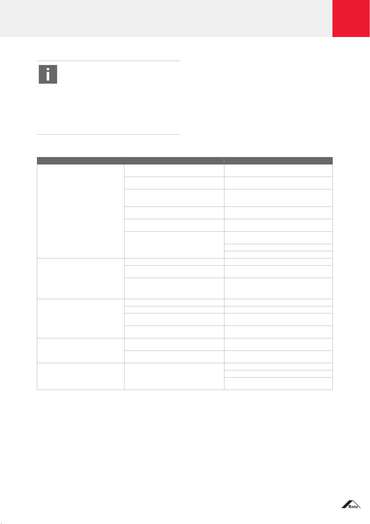
Proper operation
Roto Safe Eneo C, CC and CF
Locking the door from the outside
The Eneo C, CC and CF multipoint locking systems must
be in “night operation mode”. A reed contact must also
be fitted. As soon as the door is closed, all locking
systems extend automatically. The locking process is
complete after approximately 2 seconds.
Unlocking the door from the outside
Depending on the access control system available,
unlocking can be triggered by hand-held transmitter,
finger scan, Phone & Code, etc.
INFO
If the deadbolt is locked, the lock cannot be
opened electronically.
Unlocking the door from the inside
The Eneo C multipoint locking system can only be
unlocked using a key or electrical signal (e.g. push-
button).
The Eneo CC and CF multipoint locking systems can be
unlocked using the lever handle.
INFO
Roto Safe Eneo C and CF
A pull handle or rod handle must be fitted to
the outside of the door.
Roto Safe Eneo A and AF
Locking the door (automatically)
When closing the door, the two additional locking
systems – the automatic bolts – snap into their strikers in
the same way as the latch engages in the main lock.
These are activated automatically and the door is locked
securely at two additional points.
Additional locking using the key (night-time
locking)
Turn the key 360° once in the cylinder. The door is
locked.
Unlocking the door from the outside with day
operation mode
Depending on the access control system available,
unlocking can be triggered by hand-held transmitter,
finger scan, Phone & Code, etc.
Unlocking the door from the inside with day
operation mode
The multipoint locking system can be unlocked using the
lever handle.
Unlocking the door with night operation mode
Turn the key 360° in the cylinder. The door is unlocked.
INFO
Manual emergency operation of the door
using a key is possible at any time (e.g. in the
event of a power failure).
Roto Safe Eneo
4 · 04 / 2019 · SUG_11_EN_v0 Roto Safe Eneo Subject to change.