ROTOR LZR-B User manual

Betriebsanleitung Luftzufuhr-Rohre
Operating manual Air feed tubes
www.rotortool.com


www.rotortool.com Luftzufuhr-Rohre / Air feed tubes 3
Seite/Page
1. Allgemeines/General 4
1.1 Eigenschaften der ROTOR Luftzufuhr-Rohre/Features of ROTOR air feed tubes 4
1.2 Sicherheitshinweise/Safety instructions 4
1.3 Sachmängelhaftung/Liability for defects 5
2. Systembeschreibung /System description 6
2.1 Technische Daten/Technical data 6
2.2 Systemaufbau/System design 7
2.3 Montage der Luftzufuhr-Rohre/Mounting the air feed tubes 7
Luftzufuhr-Rohre bestehend aus festen Rohren/Air feed tubes consisting of fixed pipes 7
Luftzufuhr-Rohre bestehend aus flexiblen Schläuche/
Air feed tubes consisting of flexible hoses
8
2.4 Pneumatik-Schema/Pneumatic diagram 10
3. Pflege und Wartung / Care and maintenance 10
3.1 Allgemeines/General 10
3.2 Schmierung/Lubrication 10
3.3 Wartung / Maintenance 10
4. Anhang /Appendix 11
EG-Einbauerklärung/EC Declaration of Incorporation 11
Inhaltsverzeichnis / Table of Contents

4 Luftzufuhr-Rohre / Air feed tubes
1. Allgemeines
1.1 Eigenschaften der Luftzufuhr-Rohre
Die ROTOR Luftzufuhr-Rohre sind insbesondere
entwickelt zur sicheren und optimalen Anwen-
dung der ROTOR Präzisions-Spannfutter aber auch
geeignet zum betreiben von diversen anderen
Spannmittel.
• Die 2-Kanal-Rohre zum öffnen / schliessen
der Futter
• Die 3- und 4-Kanalrohre zur zusätzlichen
Zuführung von Kühlmittel, Luft (z.B. für
die Werkstück Anlagekontrolle) oder Fett für
Futter mit Zentralschmierung.
• Die schwingungsfreie Führung der Rohre
erfolgt durch den dem Rohrtyp entsprechen-
den Führungsflansch und Stützring.
• Die Luftzufuhr-Rohre müssen in den exakten
Längen bestellt werden.
• Siehe www.rotortool.com/Zubehör,
mehr/Luftzufuhrrohre, zu den Produk-
ten/Rohrlänge L / Spindellänge
• Die Rohre mit flexiblem Kunststoffschlauch
(max. 1’200 mm lang) erfordern einen grös-
seren Spindeldurchlass.
Detaillierte Angaben entnehmen Sie bitte der
Tabelle auf Seite 6 dieser Anleitung.
1. General
1.1 Features of air feed tubes
The ROTOR air feed tubes are especially designed
for the safe and optimal application of the ROTOR
precision chucks but also suitable for the operation
of various other clamping devices.
• 2-passage tubes for opening/closing the
chuck
• 3- and 4-passage tubes for additional supply
of coolant, air (for example for the workpiece
control system) or grease for chucks with
central lubrication.
• Vibration-free guidance of the tubes is
achieved by the guiding flange and support
ring corresponding to the tube type.
• Air feed tubes must be ordered in exact
lengths.
• See www.rotortool.com/accessories, more/
air feed tubes, to products / tube length L /
spindle length
• Tubes with flexible plastic hoses (up to
1,200mm long) require a larger spindle
passage.
For detailed information, please refer to the table
on page 6 of this manual.
1.2 Sicherheitshinweise
Nachfolgende Sicherheitshinweise sind sorgfältig
zu beachten:
• Jede Anwendung der Luftzufuhr-Rohre sollte
nach dieser Anleitung durchgeführt werden.
• WICHTIG! der Spannvorgang muss mittels
einem Druckwächter überwacht werden. Ver-
sagt die Luftzufuhr muss die Maschinen-
spindel sofort gestoppt werden (siehe 2.4
Pneumatik-Schema).
• Der Stator muss mittels einer geeigneten
Rückhalterung fixiert werden. In vielen Fällen
genügt die Rückhaltung durch die fixierten
Luftzufuhr-Schläuche. Es dürfen keine
zusätzlichen Radial- oder Axial-Kräfte durch
die Rückhalterung und die Schläuche auf den
Stator einwirken.
• Das Luftzufuhr-Rohr muss in jedem Falle am
Ende der Spindel mittels einem Führungs-
flansch präzise geführt werden, max. zulässi-
ge Rundlaufabweichung des Rotors 0.02 mm.
• Bei Spindellängen >600mm muss das Rohr
in der Spindelmitte durch einen Stützring
abgestützt werden (siehe Seite7, 2.3 Abs. 2.)
• Es ist darauf zu achten, dass das Luftzufuhr-
Rohr sich nach der Montage, dem Spann-
mittel entsprechend axial verschieben lässt.
1.2 Safety instructions
Please pay close attention to the following safety
instructions:
• The air feed tube must only be used as indicat-
ed in this manual.
• IMPORTANT! the clamping procedure must be
monitored by a pressure monitor. If the
air supply fails, the machine spindle must be
stopped immediately (see 2.4 Pneumatic
diagram).
• The stator must be held in place by a suitable
holder. In many cases, the stator can be held
simply by the fixed air hoses. The stator must
not be subject to any additional radial or axial
forces acting through the holder or the air
hoses.
• The air feed tube must always be guided by
the guiding flange at the end of the spindle;
max. allowed runout of the rotor is 0.02 mm.
• For spindle lengths >600mm the tube must
be supported in the middle by a supporting
ring (see page7, 2.3 paragraph 2.).
• Please ensure that after mounting, the air
feed tube is free to move axially in the respec-
tive clamping device

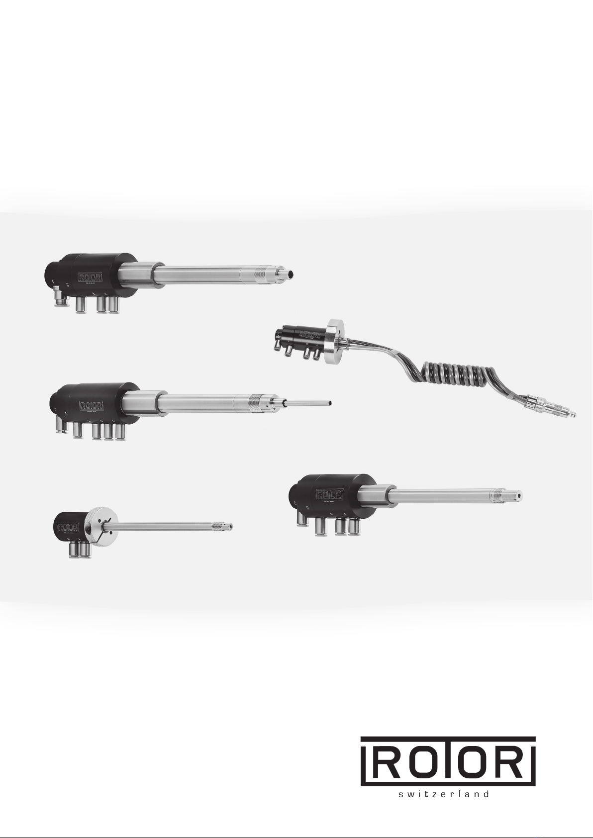
www.rotortool.com Luftzufuhr-Rohre / Air feed tubes 5
• Die zugeführte Luft muss geölt sein und darf
keine weitere Feuchtigkeit oder Verunreini-
gung enthalten, Partikelgrösse max. 5µm.
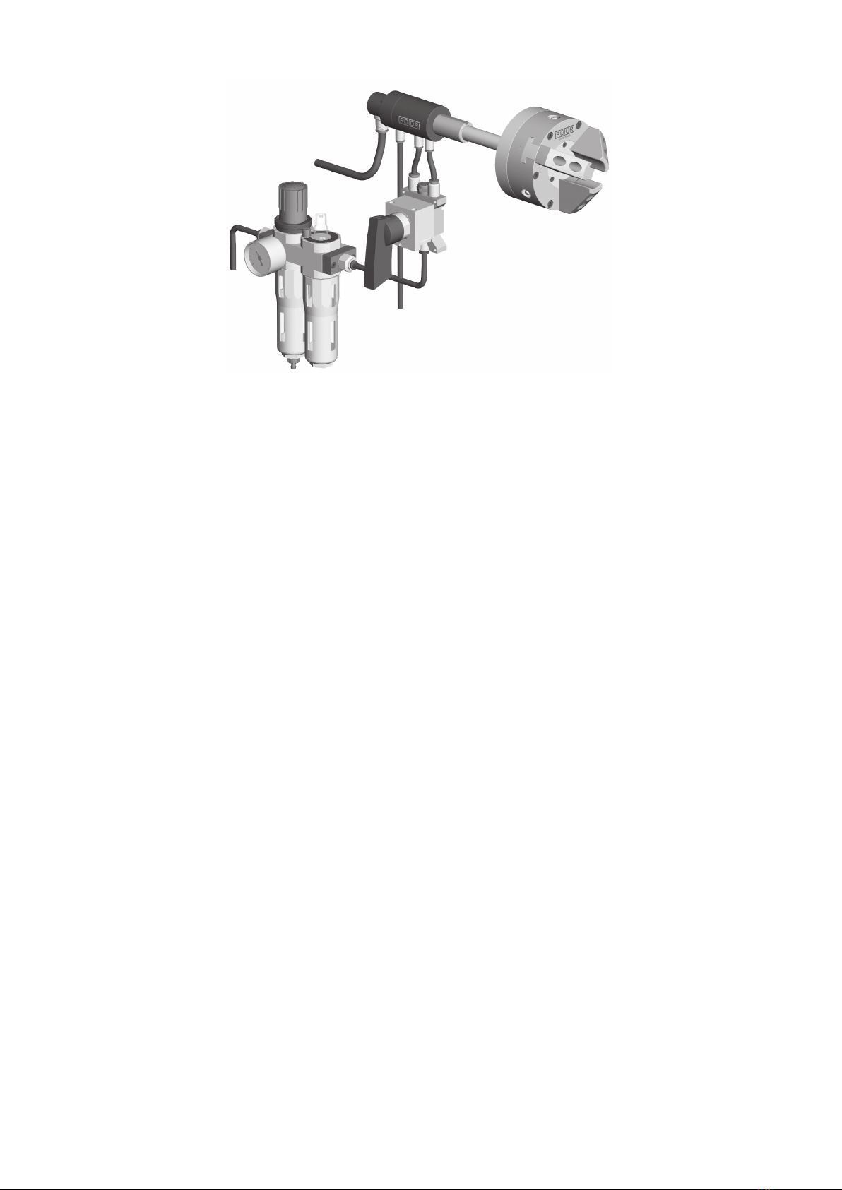
• Das Futter einige mal öffnen/schliessen bevor
es rotiert (Schmierung der Drehdurchführung).
• WICHTIG! Bevor auf C, Kühlmittel usw. ein-
geleitet wird muss geprüft werden, ob das
Futter korrekt öffnet/schliesst, d.h. korrekt
angeschlossen ist. Gelangt über die
Anschlüsse A oder B Kühlmittel in die Pneu-
matik des Präzisions-Spannfutters muss
Dieses zur Reinigung möglichst umgehend
ROTOR zugestellt werden (Rostgefahr). Wird
das Futter nicht korrekt demontiert / mon-
tiert geht die Rundlaufgenauigkeit verloren
(siehe Betriebsanleitung des Spannfutters).
• Am Anschluss E darf lediglich Luft (keine
Flüssigkeiten!!) eingeleitet werden. Dies
betrifft die Rohr-Typen BSA, BSCA, BFA, BFCA,
CFA (siehe Tabelle Seite6).
• Die max. Betriebsdrücke für das Luftzufuhr-
Rohr sowie das Spannmittel sind unbedingt
einzuhalten.
• Der Eingangsquerschnitt für Kühlmittel
(siehe Tabelle Seite 6) darf bis zum Austritt
nicht reduziert werden, ansonsten muss
auch der Eingangsquerschnitt entsprechend
angepasst werden.
• Der Stator darf während der Rotation der Spin-
del nicht berührt werden (Verletzungsgefahr).
• The air fed in must be lubricated with oil
and must not contain any further moisture or
contamination; max. particle size is 5 µm.
• Open/close the chuck several times before it
rotates (lubrication of the rotary union).
• IMPORTANT! Before entering on C, coolant,
etc., a check must be carried out to see if the
chuck opens/closes properly, i. e. is connected
correctly. If coolant enters the pneumatics
of the precision chuck via connections A or B,
it must be delivered to ROTOR for cleaning as
soon as possible (risk of rusting). If the chuck
is not disassembled / assembled correctly, con-
centricity will be lost (see operating instruc-
tions of the chuck).
• At port E, only air (no liquids!!) may be intro-
duced. This concerns the air feed tube types
BSA, BSCA, BFA, BFCA, CFA (see table page 6).
• The max. operating pressures for the air
supply pipe and the clamping device must be
strictly adhered to.
• The inlet cross section for coolant (see table
on page6) must not be reduced until it
exits, otherwise the inlet cross section must
also be adjusted accordingly.
• The stator must not be touched while the
spindle is rotating (risk of injury).
1.3 Sachmängelhaftung
Die Sachmängelhaftungsrechte des Bestellers set-
zen voraus, dass der Liefergegenstand nach Erhalt
überprüft und ROTOR der Mangel unverzüglich,
spätestens jedoch zwei Wochen nach Erhalt,
schriftlich mitgeteilt wird; verborgene Mängel
müssen ROTOR unverzüglich nach ihrer Entde-
ckung schriftlich gemeldet werden. Die Sachmän-
gelhaftung erlischt, wenn das Luftzufuhr-Rohr
zerlegt, verändert oder durch unsachgemässe
Behandlung beschädigt wurde. Ansonsten gelten
unsere allgemeinen Verkaufs- und Lieferbedin-
gungen. Dabei ist ausdrücklich zu beachten, dass
alle dynamischen Dichtelemente als Verschleiss-
teile zu betrachten sind.
ROTOR übernimmt keine Gewähr für Schäden, die
durch ungeeignete oder unsachgemässe Verwen-
dung, fehlerhaften Transport, fehlerhafte Aufbe-
wahrung, fehlerhafte Montage und Inbetriebnah-
me, mangelnde Wartung, fehlerhafte Behandlung
oder fehlerhaften Einbau durch den Besteller,
Verwendung von nicht geeignetem Zubehör oder
nicht geeigneten Ersatzteilen sowie durch natür-
liche Abnutzung entstehen, sofern die Schäden
nicht von ROTOR zu vertreten sind.
1.3 Liability for defects
The preconditions for the buyer’s rights relating to
liability for material defects are that the delivered
product is inspected upon receipt and any defects
are reported to ROTOR in writing immediately, and
not later than two weeks from the time of receipt.
Concealed defects must be reported to ROTOR in
writing immediately when they are detected. The
warranty for defects becomes void if the air feed
tube is dismantled, modified or damaged by
improper treatment. Apart from this, our General
Terms of Sale and Delivery apply. Here it is expressly
noted that all dynamic seal components are to be
considered as parts subject to wear and tear.
ROTOR does not accept any liability for damage
resulting from inappropriate or improper use,
defective transport, defective storage, faulty
assembly or commissioning, inadequate mainte-
nance, incorrect handling or installation by the
customer, the use of inappropriate accessories and
spare parts, and damage caused by natural wear
and tear, insofar as ROTOR is not responsible for
such damage.

6 Luftzufuhr-Rohre / Air feed tubes
2. Systembeschreibung
2.1 Technische Daten
2. System description
2.1 Technical data
Zur Herstellung dieser Luftzufuhr-Rohre benöti-
gen wir die genaue Angabe der Spindellänge oder
die Länge des Luftzufuhr-Rohres.
• Max. Luft-Druck zum öffnen / schliessen
der Futter, Anschlüsse A+B, 10 bar
• Max. Kühlmittel-Druck am Anschluss C,
10 bar
• Achtung!! Am Anschluss E darf nur Luft ein-
geleitet werden, max. 10 bar.
For the manufacturing of these air feed tubes we
need the exact specification of the spindle length
or the length of the air feed tube.
• Max. air pressure to open / close the chuck,
connections A + B, 10 bar
• Max. coolant pressure at port C, 10 bar
• Caution!! Only air may be introduced at
port E, max. 10 bar
Type B / BC / BL / F Type BS / BSA/BSC/BSCA (4-Kanal) / CS / CSC
Type BF / BFA / BFC / BFCA (4-Kanal) / CF / CFA / CFC / FF
Luftzufuhr-Rohre / Air feed tubes
403/20
2. Systembeschreibung 2. System description
2.1 Technische Daten 2.1 Technical data
Zur Herstellung dieser Luftzufuhr-Rohre benötigen wir die genaue Angabe der Spindellänge oder die Länge des
Luftzufuhr-Rohres.
For the manufacturing of these air feed tubes we need the exact specification of the spindle length or the length of
the air feed tube.
Type BF / BFA / BFC / BFCA (4-Kanal) / CF / CFA / CFC / FF
Abmessungen
Dimensions
Type
Best. Nr.
Order No.
A B C D E F G / H
I L K
3. / 4. Kanal
3rd / 4th passage
Drehzahl
RPM max
min-1
Futter -Ø
Chuck -Ø
mm
B LZR-B 69 4’000
BC / BL LZR-BC / BL 16 5/8“ -32 UN 8 36 32 1/8“ 118 6 C / L 3’000 80 -200
BS LZR-BS 39 55
BSA LZR-BSA 37 6 65 A
BSC LZR-BSC 39 8 87 C
BSCA LZR-BSCA
16 5/8“ -32 UN 8 23
37 6 95
6
C + A
6’000 80 -200
BF LZR-BF 2 x 6 55
BFA LZR-BFA 65 A
BFC LZR-BFC 3 x 6 22
85 4 C
BFCA LZR-BFCA 4 x 6
5/8“ -32 UN 8
25
37 6
95 3.5
74 32
C + A
6’000 80 -200
F LZR-F 7 32 25 58 10’000 50 -200
FF LZR-FF 2 x 4 M7 x 0.75 5.8 16 37 55 30 28 6’000 50
CS LZR-CS 47
CSC LZR-CSC 11 7/16“-28 UNEF
8.6 18 35 6 72 3 C 9’600 50 - 200
CF LZR-CF 2 x 4 55
CFA LZR-CFA 65 A
CFC
LZR-CFC
3 x 4 7/16“-28 UNEF
8.6 17 37 6
85
3 48 28
C
6’000 50 -200
3. / 4. Kanal 3rd / 4th passage
Luft, air Kühlmittel, coolant Fett, grease
A
C
L
•Max. Luft-Druck zum öffnen / schliessen
der Futter, Anschlüsse A+B, 10 bar
•Max. Kühlmittel-Druck am Anschluss C, 10 bar
•Achtung!! Am Anschluss E darf nur Luft einge-
leitet werden, max. 10 bar.
Type B / BC / BL / F
•Max. air pressure to open / close the chuck,
connections A + B, 10 bar
•Max. coolant pressure at port C, 10 bar
•Caution!! Only air may be introduced at port
E, max. 10 bar
Type BS / BSA / BSC / BSCA (4-Kanal) / CS / CSC
Type BS / BSC / BSA / BSCA (*4-Kanal) /
CCSCCSCCSCSCSCCSC

www.rotortool.com Luftzufuhr-Rohre / Air feed tubes 7
2.2 Systemaufbau 2.2 System design
2.3 Montage der Luftzufuhr-Rohre
Luftzufuhr-Rohre bestehend aus festen Rohren
1. Rohr-Führungsflansch in das Maschinen-
Spindelende einpassen, im ∅ca.0.2mm
kleiner als die Bohrung, sodass das Luftzu-
fuhr-Rohr auf die max. zulässige Rundlauf-
abweichung justiert werden kann.
Führungsflansche zum klemmen, Typ B-FF
und F-FF, einpassen im ∅0.03 mm kleiner als
die Bohrung, sodass in geklemmtem Zustand
das Luftzufuhr-Rohr sich axial frei bewegen
kann.
2. Bei Rohrlänge >600mm und Drehzahlen
über 1’000 min–1 das Rohr in der Spindelmit-
te zusätzlich mit einem Stützring abstützen.
Stützring im A-∅ca.0.03mm kleiner als die
Spindel-Bohrung. Dabei ist darauf zu achten,
dass das Rohr sich axial frei bewegen lässt.
3. Das Gewinde reinigen und das Rohr von
Hand mittels dem Rändelring resp. Füh-
rungsflansch in das bereits montierte Futter
einschrauben und festziehen.
Bitte keine Zange verwenden um Deformati-
on des Gewindes und Bruch der Klebestellen
zu vermeiden.
4. Führungsflansch an Maschinenspindel fest-
schrauben, die mitgelieferten Sechskant-
schrauben am Zwischenflansch festziehen.
5. Schrauben am Führungsflansch nochmals
leicht lösen und das Luftzufuhr-Rohr auf die
max. zulässige Rundlaufabweichung von
0.02mm ausrichten, Schrauben festziehen.
6. Flexible Schläuche anschliessen.
A/B = öffnen/schliessen
C = Kühlmittel/Fett
E = nur Luft!! (keine Flüssigkeiten)
D = Entlastungs-/Leckageanschluss
2.3 Mounting the air feed tubes
Air feed tubes consisting of fixed pipes
1. Fit the pipe guide flange into the machine
spindle end approx. 0.2 mm smaller than the
bore in the ∅so that the air feed tube can be
adjusted to reach the max. permissible con-
centricity deviation.
Fit clamping guide flanges type B-FF and F-FF
smaller than the bore in ∅0.03 mm so that
the air feed tube is free to move axially when
clamped.
2. For tube lengths > 600 mm and speeds over
1,000 rpm, the tube must be given additional
support at the middle of the spindle by a sup-
port ring. Support ring in A-∅approx.0.03
mm smaller than the spindle bore.
Please ensure that the tube can move freely in
the axial direction.
3. Clean the thread and then screw the tube into
the chuck and tighten it by hand using the
knurled ring or guide flange.
Please do not use pliers as these might deform
the thread or break the splices.
4. Tighten the guide flange to the machine spin-
dle and tighten the hexagon bolts provided on
the intermediate flange.
5. Slightly loosen the screws on the guide flange
again and align the air feed tube to the maxi-
mum permitted runout of 0.02 mm, tighten
the screws.
6. Connect up the flexible hoses.
A/B = open / close
C = coolant / grease
E = only air!! (no liquids)
D = discharge/leakage connection

8 Luftzufuhr-Rohre / Air feed tubes
Bei Verwendung eines Handhebel-Ventils ist
es aus Sicherheitsgründen zu empfehlen,
beim Wechsel der Spannrichtung die Schläu-
che zu vertauschen, um sowohl bei Innen-
als auch bei Aussenspannung immer die glei-
che Hebelstellung zu haben.
7. Haltegabel (ist vom Kunden zu fertigen)
montieren. Die Haltegabel ist so anzubrin-
gen, dass sie an den Luftverschraubungen
angreifen kann. Dabei ist darauf zu achten,
dass das Luftzufuhr-Rohr einen, dem Spann-
mittel entsprechenden Axialhub fahren
kann.
Möglichst leichte Schläuche verwenden,
entsprechend den montierten Original-
Anschlüsse. Es dürfen keine zusätzlichen
Radial- oder Axial-Kräfte durch die Rück-
halterung oder Schläuche auf den Stator
einwirken.
8. Vor der Zuleitung der Luft in das Luftzufuhr-
Rohr muss eine Luftwartungseinheit beste-
hend aus Manometer, Wasserabscheider,
Feinfilter und Oeler eingebaut werden.
WICHTIG! der Spannvorgang muss mittels
einem Druckwächter überwacht werden
(siehe Pneumatik-Schema auf Seite10).
When using a hand-lever valve, for safety
reasons it is advisable to swap the hoses when
changing the clamping direction in order
always to have the same lever position for
both external and internal clamping.
7. Mount the holding bracket (to be provided by
the customer) in place. The bracket must be
mounted so that it can hold the stator at the
air connectors. It is important to ensure that
the air feed tube can move an axial stroke cor-
responding to the clamping device.
Use the lightest hoses possible, according to
the assembled original connector. The stator
must not be subject to any additional radial
or axial forces acting through the holder or
the hoses.
8. An air maintenance unit, consisting of pres-
sure gauge, water separator, fine filter and
lubricator, must be installed upstream from
where the air is fed into the air feed tube.
IMPORTANT! the clamping process must be
monitored by means of a pressure monitor
(see Pneumatic diagram on page 10).
Type B / BC / BL / F Type BS / BSA/BSC/BSCA (4-Kanal) / CS / CSC
Luftzufuhr-Rohre bestehend aus flexiblen
Schläuchen
1. Den Führungsflansch der Drehdurchführung
in das Maschinen-Spindelende einpassen, im
∅ca.0.2mm kleiner als die Bohrung, sodass
die Drehdurchführung auf die max. zulässige
Rundlaufabweichung justiert werden kann.
2. Anschlussgewinde im Futter und am Nippel
reinigen und den Nippel von Hand in das Fut-
ter einschrauben und festziehen. Bitte keine
Zange verwenden um Beschädigung des
Gewindes zu vermeiden.
3. Den Flexschlauch am Nippel wie folgt
anschliessen: schwarz an A = öffnen; blau an
B = schliessen; grau an C = zentrale Zufuhr.
Air feed tubes consisting of flexible hoses
1. Fit the guide flange of the rotary unit into the
machine spindle end, in ∅approx. 0.2 mm
smaller than the bore so that the rotary unit
can be adjusted to the max. permissible con-
centricity deviation.
2. Clean the connection threads in the chuck and
nipple, and screw the nipple into the chuck
by hand and tighten. Please do not use pliers
as these may damage the thread.
3. Connect the flexible hose to the nipple as fol-
lows: black to A = open; blue to B = close; grey
to C = central feed.

www.rotortool.com Luftzufuhr-Rohre / Air feed tubes 9
4. Den Flexschlauch in die Spindeldurchfüh-
rung einführen und das Futter an der Spin-
delnase festschrauben. Die Montage des
Futters ist gemäss der entsprechenden
Betriebsanleitung vorzunehmen.
ROTOR Betriebsanleitungen siehe auch unter
www.rotortool.com
5. Den Flexschlauch evtl. ablängen und wie
folgt an die Drehdurchführung anschliessen:
schwarz an A = öffnen; blau an B = schlies-
sen, grau an C/E = zentrale Zufuhr (z.B. Kühl-
mittel/Luft)
6. Drehdurchführung auf die max. zulässige
Rundlaufabweichung von 0.02mm ausrich-
ten, Schrauben festziehen.
7. Zuleitungsschläuche am Drehverteiler
anschliessen. Vor der Zuleitung der Luft in
das Luftzufuhr-Rohr muss eine Luftwar-
tungseinheit bestehend aus Manometer,
Wasserabscheider, Feinfilter und Oeler einge-
baut werden.
WICHTIG! der Spannvorgang muss mittels
einem Druckwächter überwacht werden
(siehe Pneumatik-Schema auf Seite10).
8. Haltegabel (ist vom Kunden zu fertigen)
montieren. Die Haltegabel ist so anzubrin-
gen, dass sie an den Luftverschraubungen
angreifen kann. Möglichst leichte Schläuche
verwenden. Es dürfen keine zusätzlichen
Radial- oder Axial-Kräfte durch die Rückhalte-
rung oder Schläuche auf den Stator
einwirken.
9. WICHTIG! Bevor auf C, die zentrale Zufuhr,
Kühlmittel usw. eingeleitet wird muss
geprüft werden, ob das Futter korrekt öff-
net/schliesst., d. h. korrekt angeschlossen ist.
Gelangt über die Anschlüsse A oder B Kühl-
mittel in die Pneumatik des Präzisions-
Spannfutters muss Dieses zur Reinigung
möglichst umgehend ROTOR zugestellt wer-
den. Wird das Futter nicht umgehend korrekt
demontiert / montiert kann im Pneumatik-
Zylinder Rost ansetzen. Wird das Futter nicht
korrekt demontiert / montiert ist die Rund-
laufgenauigkeit nicht mehr gewährleistet
4. Insert the flexible hose into the spindle and
screw the chuck to the spindle nose. The
assembly of the chuck must be carried out
according to the corresponding operating
instructions. For ROTOR manuals, also see
www.rotortool.com
5. If required, cut the flexible hose to length and
connect to the rotary union as follows:
black to A = open; blue to B = close, grey to
C/E = central supply (e. g., coolant/air)
6. Align the rotary union to the max. permissible
concentricity deviation of 0.02mm, tighten
screws.
7. Connect the supply hoses to the rotary union.
Before feeding the air into the air feed tube,
an air conditioning unit consisting of a
manometer, water separator, fine filter and
oiler must be installed.
IMPORTANT! the clamping process must be
monitored by means of a pressure monitor
(see Pneumatic diagram on page 10).
8. Mount the holding bracket (to be manufac-
tured by the customer). The holding bracket
is to be attached so that it can engage the air
connectors. Use the lightest hoses possible.
The stator must not be subject to any addi-
tional radial or axial forces acting through the
holder or the hoses.
9. IMPORTANT! Before initiating on C, the cen-
tral supply, coolant, etc., it must be checked if
the chuck opens/closes correctly, i. e. is con-
nected correctly. If coolant enters the pneu-
matics of the precision chuck via connections
A or B, it must be delivered to ROTOR as soon
as possible for cleaning. If the chuck is not cor-
rectly disassembled/assembled immediately,
rust can start to develop in the pneumatic cyl-
inder. If the chuck is not disassembled / assem-
bled correctly, concentricity is no longer
guaranteed.
Type BF / BFA / BFC/BFCA/CF/CFA / CFC

10 Luftzufuhr-Rohre / Air feed tubes
2.4 Pneumatik-Schema für Aussenspannung 2.4 Pneumatic diagram for outside clamping
3. Pflege und Wartung
3.1 Allgemeines
Die zugeführte Luft muss geölt sein und darf kei-
ne weitere Feuchtigkeit oder Verunreinigung ent-
halten, Partikelgrösse max. 5 µm.
3.2 Schmierung
Der rotierende Verteiler wird durch den Oelnebel
der Luftwartungs-Einheit geschmiert. Das zu
verwendende Hydraulik-Oel muss gefiltert sein,
max. 5 µm und die ISO Klasse 46 aufweisen.
3.3 Wartung
• Es ist darauf zu achten, dass jederzeit genü-
gend Oel im Behälter der Luftwartungsein-
heit vorhanden ist.
• Regelmässig prüfen ob sich der Stator nach
wie vor frei bewegen lässt.
• Die Drehdurchführung ist gleitgelagert. In
Folge des benötigten Lagerspiels entweicht,
meist hörbar, eine geringe Menge Luft.
Diese geölte Luft bewirkt das schmieren der
Drehdurchführung auch während der
Bearbeitung.
3. Care and maintenance
3.1 General
The air fed in must be lubricated with oil and must
not contain any further moisture or contamina-
tion; max. particle size 5 µm.
3.2 Lubrication
The rotating union is lubricated by the oil mist
from the air maintenance unit. The hydraulic
oil that is used must be filtered, max. 5 µm and of
ISO grade 46.
3.3 Maintenance
• Make sure there is always enough oil in the
tank of the air maintenance unit.
• Check regularly that the stator can still move
freely.
• The rotary union has a slide bearing. Because
of the required bearing clearance, a small
amount of air escapes and is usually audible.
This oiled air serves to lubricate the rotary
union also during processing.
Für Innenspannung sind die Schläuche auf die
Anschlüsse A und B zu tauschen, ebenso der
Druckwächter.
WICHTIG! Der Druckwächter muss immer an die
Leitung «spannen» angeschlossen sein!
For internal clamping, the hoses must be
exchanged for connections A and B, as well as the
pressure switch.
IMPORTANT! The pressure switch must always be
connected to the cable “clamp”.

www.rotortool.com Luftzufuhr-Rohre / Air feed tubes 11
4. Anhang 4. Appendix
EG-Einbauerklärung
Hiermit erklären wir, dass folgendes Produkt:
Produktbezeichnung: Luftzufuhr-Rohre zum betätigen der ROTOR Präzisions-Spannfutter
Typenbezeichnung: B, BC, BL, BS, BSA, BSC, BSCA, BF, BFA, BFC, BFCA, F, FF, CS, CSC, CF, CFA, CFC
den zutreffenden, grundlegenden Anforderungen der Richtlinie Maschinen, 2006/42/EG entspricht.
Die unvollständige Maschine darf erst dann in Betrieb genommen werden, wenn gegebenenfalls fest-
gestellt wurde, dass die Maschine, in die die unvollständige Maschine eingebaut werden soll, den
Bestimmungen der Maschinenrichtlinie (2006/42/EG) entspricht.
Angewandte harmonisierte Normen, insbesondere:
SN EN 1550+A1
Die zur unvollständigen Maschine gehörenden speziellen technischen Unterlagen wurden gemäss
Anhang VII Teil B erstellt.
Der Hersteller verpflichtet sich, diese speziellen technischen Unterlagen zur unvollständigen Maschine
einzelstaatlichen Stellen auf begründetes Verlangen zu übermitteln.
EC Declaration of Incorporation
We hereby declare that the following product:
Product designation: Air feed tubes for ROTOR High Precision Power Chucks
Type designation: B, BC, BL, BS, BSA, BSC, BSCA, BF, BFA, BFC, BFCA, F, FF, CS, CSC, CF, CFA, CFC
complies with the applicable basic requirements of the Machinery Directive 2006/42/EC.
The partly completed machinery may only be put into service if it has been established that, where
applicable, the machine into which the partly completed machinery is to be installed complies with the
provisions of the Machinery Directive (2006/42/EC).
Designed in conformity with harmonised standards, in particular:
SN EN 1550+A1
The special technical documentation for the partly completed machinery has been compiled in
accordance with Annex Vll, part B.
The manufacturer undertakes to forward this special technical documentation regarding the partly
completed machinery to the national authorities in response to a reasoned request.
Hersteller/Manufacturer ROTOR TOOL AG
Esslingerstrasse 13
CH-8618 Oetwil am See
Ort, Datum
Location, date Oetwil am See, 26.11.2019 Daniel Roider, Q-Management

ROTOR TOOL AG
Esslingerstrasse 13
CH-8618 Oetwil am See
Telefon +41 44 929 24 62
Telefax +41 44 929 15 63
info@rotortool.com
www.rotortool.com
Printed in Switzerland 08.2020
This manual suits for next models
16
Table of contents