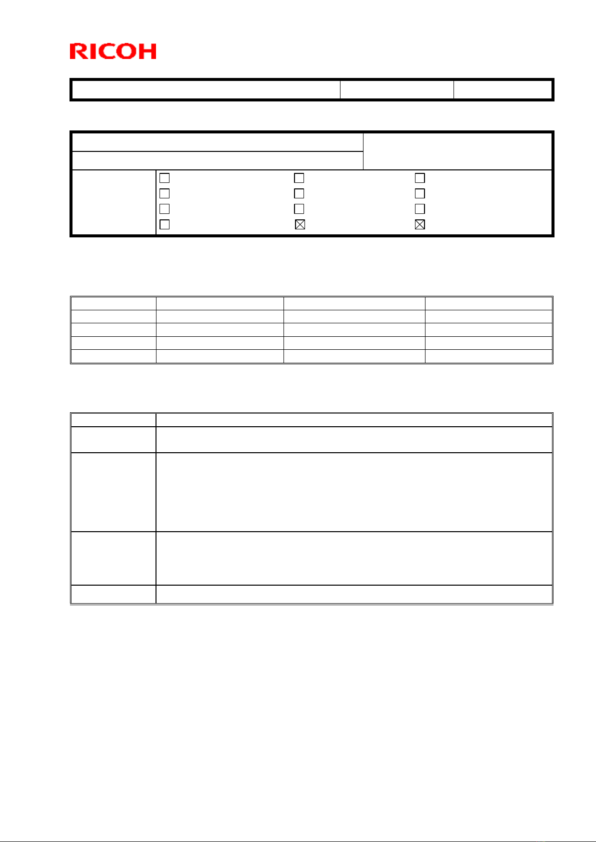
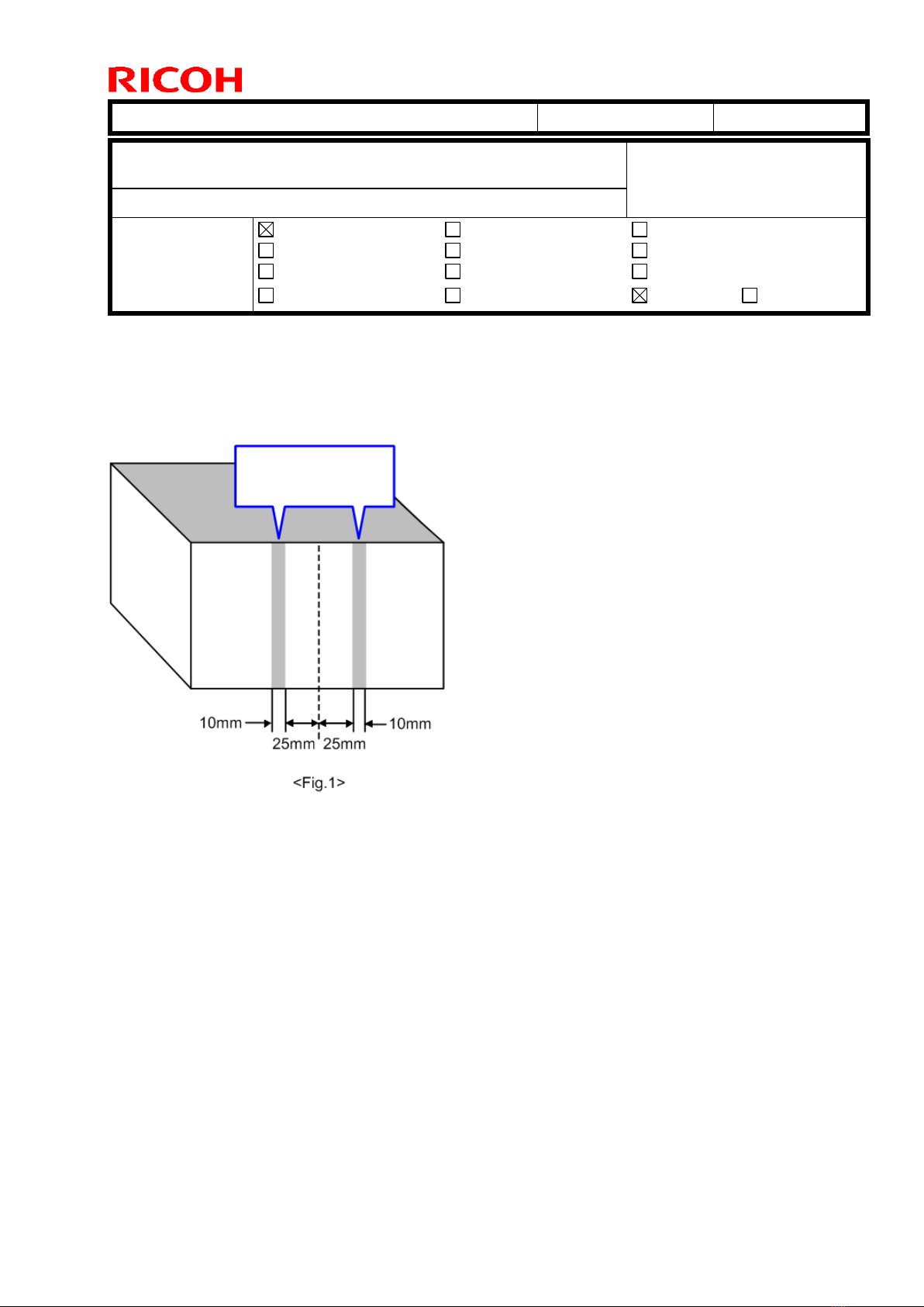
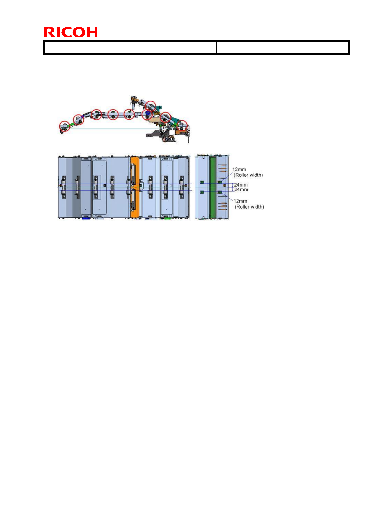
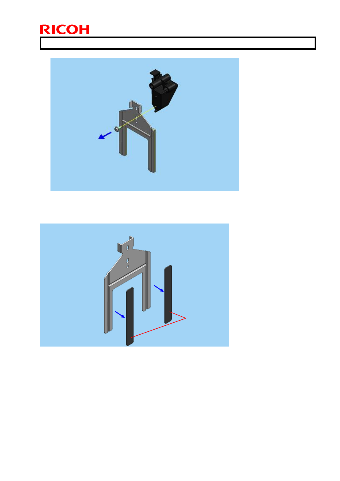
Ricoh Stacker SK5030 Service manual

Technical Bulletin PAGE: 1/1
Reissued: 29-Jul-16
Model: Stacker_SK5030_1
Date: 11-Dec-14
No.: RD776001a
RTB Reissue
The items in bold italics have been corrected or added.
Subject: Firmware Release Note: Stacker_SK5030_1
Prepared by: A. Tajima
From: 1st PP Tech Service Sect., PP Tech Service Dept.
Classification:
Troubleshooting
Mechanical
Paper path
Part information
Electrical
Transmit/receive
Action required
Service manual revision
Retrofit information
Product Safety Other (Firmware)
Tier 2
This RTB has been issued to announce the firmware release information for the
Stacker_SK5030_1.
Version
Program No.
Effective Date
Availability of RFU
01.070:06
D7765300E_up
July 2016 production
Not available
01.060:06
D7765300D_up
July 2015 production
Not available
01.050:06
D7765300C_up
June 2015 production
Not available
01.000:06
D7765300B_up
1st Mass production
Not available
Note: Definition of Availability of RFU via @Remote
“Available”: The firmware can be updated via RFU or SD card.
“Not available”: The firmware can only be updated via SD card.
Version
Modified Points or Symptom Corrected
01.070:06
Symptom corrected:
The stack may gradually slant.
01.060:06
Error Correction
-Jam in GBC StreamPunch Ultra under the following conditions:
i. Single punch on A3/DLT
ii. Double punch on A4/LT LEF/SEF, A3/DLT
iii. Punch on mixed size booklet
-SC990 in sheet by sheet shifting
01.050:06
-Jam in BookletFinisher SR5060, if punched on the GBC StreamPunch
Ultra.
-SC990, if two high capacity stackers are connected in tandem and a jam
occurs in GBC StreamPunch Ultra.
01.000:06
1st Mass production

Technical Bulletin PAGE: 1/1
Reissued: 29-Jul-16
Model: Stacker_SK5030_2
Date: 11-Dec-14
No.: RD776002a
RTB Reissue
The items in bold italics have been corrected or added.
Subject: Firmware Release Note: Stacker_SK5030_2
Prepared by: A. Tajima
From: 1st PP Tech Service Sect., PP Tech Service Dept.
Classification:
Troubleshooting
Mechanical
Paper path
Part information
Electrical
Transmit/receive
Action required
Service manual revision
Retrofit information
Product Safety Other (Firmware)
Tier 2
This RTB has been issued to announce the firmware release information for the
Stacker_SK5030_2.
Version
Program No.
Effective Date
Availability of RFU
01.070:06
D7765300E_down
July 2016 production
Not available
01.060:06
D7765300D_ down
July 2015 production
Not available
01.050:06
D7765300C_ down
June 2015 production
Not available
01.000:06
D7765300B_down
1st Mass production
Not available
Note: Definition of Availability of RFU via @Remote
“Available”: The firmware can be updated via RFU or SD card.
“Not available”: The firmware can only be updated via SD card.
Version
Modified Points or Symptom Corrected
01.070:06
Symptom corrected:
The stack may gradually slant.
01.060:06
Error Correction
-Jam in GBC StreamPunch Ultra under the following conditions:
i. Single punch on A3/DLT
ii. Double punch on A4/LT LEF/SEF, A3/DLT
iii. Punch on mixed size booklet
-SC990 in sheet by sheet shifting
01.050:06
-Jam in BookletFinisher SR5060, if punched on the GBC StreamPunch
Ultra.
-SC990, if two high capacity stackers are connected in tandem and a jam
occurs in GBC StreamPunch Ultra.
01.000:06
1st Mass production

Technical Bulletin PAGE: 1/1
Model: Stacker_SK5030
Date: 1-Mar-16
No.: RD776003
Subject: High Capacity Stacker SK5030: Label Paper Jams in the
Straight Paper Path
Prepared by: T.Miyamoto
From: 1st Tech Service Sect., PP Tech Service Dept.
Classification:
Troubleshooting
Mechanical
Paper path
Part information
Electrical
Transmit/receive
Action required
Service manual revision
Retrofit information
Product Safety
Other ( )
Tier 2
Tier 0.5
SYMPTOM
Jam occurs with LEF A4 adhesive label paper fed through the straight paper path of High
Capacity Stacker SK5030.
CAUSE
Smooth surface of label paper tends to stick to the curved guide plate at the exit.
[A]: Straight paper path
[B]: Exit
[C]: Entrance
The problem does not occur at the entrance, because the junction gate prevents the paper
from adhering to the guide plate.
SOLUTION
Switch to SEF. This will reduce the surface contact area between the sheet and exit guide
plate. Also, the sheet becomes longer in the feed direction, enabling transport by two
rollers in the guide plate, instead of one.

Technical Bulletin PAGE: 1/1
Model: Stacker_SK5030
Date: 2-Mar-16
No.: RD776004
Subject: High Capacity Stacker SK5030: Top most sheet separates
from the stack when pulling out the cart
Prepared by: T.Miyamoto
From: 1st Tech Service Sect., PP Tech Service Dept.
Classification:
Troubleshooting
Mechanical
Paper path
Part information
Electrical
Transmit/receive
Action required
Service manual revision
Retrofit information
Product Safety
Other ( )
Tier 2
Tier 0.5
SYMPTOM
When the cart is pulled out after the stacker is full, the top sheet of the stack separates
from the stack.
CAUSE
The paddle catches the top sheet of the stack.
OCCURRENCE CONDITIONS
The risk of the problem is higher when the following conditions are met:
Slippery paper
Solid images
SOLUTION
Place the paper holder on the paper stack before moving the cart.

Technical Bulletin PAGE: 1/2
Model: Stacker_SK5030
Date: 2-Feb-16
No.: RD776005
Subject: Troubleshooting roller marks on paper edges caused by the
High Capacity Stacker SK5030
Prepared by: T.Miyamoto
From: 1st Tech Service Sect., PP Tech Service Dept.
Classification:
Troubleshooting
Mechanical
Paper path
Part information
Electrical
Transmit/receive
Action required
Service manual revision
Retrofit information
Product Safety
Other ( )
Tier 2
Tier 0.5
SYMPTOM
Roller marks 10mm in width appear on the leading edge of the paper, 25mm from the
center of the paper, when using the High Capacity Stacker SK5030.
CAUSE
Toner adheres to the feed rollers of the High Capacity Stacker SK5030.
Roller marks on
leading edge

Technical Bulletin PAGE: 2/2
Model: Stacker_SK5030
Date: 2-Feb-16
No.: RD776005
SOLUTION
Clean the following 9 rollers in the High Capacity Stacker.

Technical Bulletin PAGE: 1/8
Model: Loire
Date: 27-Sep-16
No.: RD776006
SYMPTOM
Poor stacking with the High Capacity Stacker SK5030 when using the following paper
type.
- Thickness 4 (163.0g/m2) or less plain paper (uncoated)
Feed direction⇒
CAUSE
Paper with the characteristics above enable the vibration caused by the paddle rotation to
travel to the stacked sheets. As a result, the leading edge stopper cannot be moved to the
correct position. (See APPENDIX below for more details).
Potentially affected units
All models of the High Capacity Stacker SK5030.
Product code:
D77617
D77627
Subject: Troubleshooting: poor stacking
Prepared by: Y. Tanimoto
From: FQM 4G, QAC
Classification:
Troubleshooting
Mechanical
Paper path
Product Safety
Part information
Electrical
Transmit/receive
Other ( )
Action required
Service manual revision
Retrofit information
Tier2

Technical Bulletin PAGE: 2/8
Model: Loire
Date: 27-Sep-16
No.: RD776006
SOLUTION
Note: This solution is only affective for paper conforming to the conditions mentioned
above.
PROCEDURE
Part number
Description
Q’ty
The firmware
v01.070:06 or later
1
D7767004
(Feeler extension part )
FILM:SURFACE OF PAPER
SENSOR
1
D4473413
(Rubber part)
CUSHION:STOPPER
2
D7767003
(Sponge part)
CUSHION:STOPPER:3MM
2
-
Alcohol
Apprx. amount
-
Cleaning cloth
Step 1.
Check the version of firmware installed in the High Capacity Stacker SK5030.
If v01.070:06 or later is already installed, go to step 2.
If not, install the latest version and go to step 2
Step 2.
Install the feeler extension part (FILM:SURFACE OF PAPER SENSOR ; P/N D7767004).
The paper height is lowered 3mm from the normal position, and
the vibration of the paddle against the stacked papers will be
reduced.
How to attach the feeler extension part
1) Remove the end fence assembly from the stacker.
(Refer to Shift Tray Exit Sensor, Paper Height Sensor in
Replacement and adjustment on the service manual of Stacker)

Technical Bulletin PAGE: 3/8
Model: Loire
Date: 27-Sep-16
No.: RD776006
2) Wipe the area where the feeler extension will be attached with a cloth and a small
amount of alcohol.
3)Attach the feeler extension part to the feeler as shown below.
Area to wipe
Feeler:paper detection(D4472821)
End fence assembly
Press the edge against the base of the feeler.
Put the two end faces together.
Feeler extension part (D7767004)

Technical Bulletin PAGE: 4/8
Model: Loire
Date: 27-Sep-16
No.: RD776006
4) Reinstall the parts in the reverse order.
Step 3.
Install the cushion parts (D7767003, D4473413).
The pushing force of the paddle is reduced by lowering the paper height. As a result, the
alignment accuracy of the stacked paper will get worse. To prevent this, add the cushion
parts to the stopper to improve the pushing force.
Important:
The sponge parts (D7767003) will deteriorate
over time. Check them whenever visiting the
site and replace if necessary.
Adjust the SP settings to improve the
alignment accuracy as necessary.
Stopper:
1st Stacker SP6-603
2nd Stacker SP6-609
Jog fence
1st Stacker SP6-602
2nd Stacker SP6-608
How to attach the modified parts to the stopper
1) Remove D4473412 STOPPER: LEADING EDGE: SUB-ASS'Y from the Jogger Unit.
Note: There is no need to remove the Jogger Unit from the machine.
(M3x8 Plastic screw)

Technical Bulletin PAGE: 5/8
Model: Loire
Date: 27-Sep-16
No.: RD776006
2)Remove the 2 rubber parts (D4473413) and dispose of them.
3) Wipe the 2 surfaces where the rubber parts were attached using a cloth and a small
amount of alcohol.
Rubber part
D4473413

Technical Bulletin PAGE: 6/8
Model: Loire
Date: 27-Sep-16
No.: RD776006
4) Attach the two sponges (D7767003) as shown.
5) Attach the rubber parts (D4473413) to each sponge, as shown.
Rubber part
D4473413
Sponge
(3mm thick)

Technical Bulletin PAGE: 7/8
Model: Loire
Date: 27-Sep-16
No.: RD776006
6)Reattach the stopper assembly.
Attachment completed:
Rubber part
D4473413
Stopper: Leading edge:
D4473414
Sponge(3mm thick)
D7767003

Technical Bulletin PAGE: 8/8
Model: Loire
Date: 27-Sep-16
No.: RD776006
APPENDIX
Poor stacking occurrence mechanism
1. Normally, paper is pushed against the end fence by both
the paddle and the leading edge stopper.
2. Depending on the conditions and characteristics of the
paper, the top of the paper can push some of the lower
sheets toward the stopper. The vibration from the paddle
rotation is transmitted to the stack.
3. At this time, the stopper cannot push the papercorrectly,
because some of the shifted sheets are interfering with
the stopper. The stop position is then shifted from the
normal position, which worsens the stacking quality.
Sheets of paper shifting in groups Stop-position shift
・
Paddle
Paper

Technical Bulletin PAGE: 1/4
Model: High Capacity Stacker SK5030
Date: 18-Nov-17
No.: RD776007
Subject: Troubleshooting stuck tray
Prepared by: Takuya Hirakawa
From: Field Quality Management Group 4, FQM Dept, QAC
Classification:
Troubleshooting
Mechanical
Paper path
Part information
Electrical
Transmit/receive
Action required
Service manual revision
Retrofit information
Product Safety
Other ( )
Tier 2
Tier 0.5
SYMPTOM
The tray is stuck and does not lift up/down properly, because the drive gear is broken and
the tray bracket is slanted against the belts.
CAUSE
Grease applied to the drive components of the shift tray is dried up.
SOLUTION
Apply grease (HEAT RESISTING GREASE MT-78, p/n: 54479078) to the drive
components of the shift tray using the procedure described below based on PM cycle of
the mainframe. (Recommend cycle: Every 500K)
Product name
PM cycle
Pro C7100S, Pro C7110S, Pro C7100SX, Pro C7110SX
400K
Pro C7100, Pro C7110, Pro C7100X, Pro C7110X
400K
Pro C9100, Pro C9110
900K
Pro 8100EX, Pro 8100S, Pro 8110S, Pro 8120S
600K
Pro 8110, Pro 8120
600K
Pro 8200EX, Pro 8200S, Pro 8210S, Pro 8220S
600K
Pro 8210, Pro 8220
600K
PROCEDURE
1. Remove the rear lower cover [A] and the rear upper cover [B]. (Screw x8; 4 each)

Technical Bulletin PAGE: 2/4
Model: High Capacity Stacker SK5030
Date: 18-Nov-17
No.: RD776007
2. Remove the vertical plate [A]. (Screw x4)
3. Remove the belt cover plate [A] (8 x screws).
4. Remove the drive cover plate [A]. (2 x screws)

Technical Bulletin PAGE: 3/4
Model: High Capacity Stacker SK5030
Date: 18-Nov-17
No.: RD776007
5. Apply grease to the gears/wheel by dividing the drops, each approximately 6mm (1/4
inch) in diameter.
Gears [A] : 5 drops
Worm wheel [B]: 10 drops
Worm gear [C] : 5 drops
6. Remove the front right cover [A]. (Screw x3)
7. Remove the plates [A]. (Screw x8; 4 each)
[A]
[B]
[C]

Technical Bulletin PAGE: 4/4
Model: High Capacity Stacker SK5030
Date: 18-Nov-17
No.: RD776007
8. Remove the left cover [A]. (Screw x4)
9. Apply grease to the plate rails on the entrance side [A] and exit side [B] by making 3
drops, each approximately 6mm (1/4 inch) in diameter.

Technical Bulletin PAGE: 1/1
Model: Vacuum Feed LCIT Date: 16-Jan-18 No.: RD776008
Subject: Rusted Tray Cart Handle Prepared by: H Kawamura
From: PPCS Section, CIP Product Quality Management Dept.
Classification: Troubleshooting
Mechanical
Paper path
Part information
Electrical
Transmit/receive
Action required
Service manual revision
Retrofit information
Product Safety Other ( ) Tier 2 Tier 0.5
SYMPTOM
White-colored rust forms on the handle for the tray cart.
CAUSE
Some of the liquid coating (plating solution) applied to the handle remained inside the
structure, and later leaked out of the hole(s). As a result, the coating could not dry
properly, and reacted with the handle’s metallic exterior.
SOLUTION
If the rust appears on the handle at installation, replace with the following part:
P/N: D7769901
Description: Grip : Shift Tray : Ass’y

Technical Bulletin PAGE: 1/8
Model:
High Capacity Stacker SK5030
Date:
7-Feb-18
No.:
RD776009
Subject:
Worn worm gear
Prepared by:
H Kawamura
From: PPCS Section, CIP Product Quality Management Dept.
Classification: Troubleshooting
Mechanical
Paper path
Part information
Electrical
Transmit/receive
Action required
Service manual revision
Retrofit information
Product Safety Other ( ) Tier 2 Tier 0.5
SYMPTOM
A loud noise is heard coming from the stacker, and the shift tray does not move.
CAUSE
The worm gear gets worn when the paper tray is full with relatively heavy paper.
SOLUTION
If the symptom occurs and the worm gear appears worn, replace the following as a set:
See PROCEDURE below.
P/N: D3DK4111
Description: BRACKET:DRIVE:UPPER LOWER:ASS'Y
P/N: D3DK4121
Description: WORM GEAR:UPPER LOWER:ASS'Y
Production cut-in Serial Number: G257E720017
Other Ricoh Industrial Equipment manuals
Popular Industrial Equipment manuals by other brands

Aerotech
Aerotech ABRX Hardware manual

HADEF
HADEF 19/90 Installation, operating and maintenance instructions

ZKTeco
ZKTeco Tripod Turnstile Maintenance manual

Ingersoll-Rand
Ingersoll-Rand Genuine 10208 quick start guide

R.V.R. Elettronica
R.V.R. Elettronica RXRL-NV/2 Technical manual

SMC Networks
SMC Networks HEBC002-WA10 manual

REHOBOT
REHOBOT CH Series operating instructions

Nippon Oil Pump
Nippon Oil Pump C Series User instruction manual

Gilbarco
Gilbarco Veeder-Root FlexPay IV Encore 700 S manual

Eaton
Eaton DILP-XHB Series Instruction leaflet

Beckhoff
Beckhoff AA3000 operating instructions

Astronergy
Astronergy CHSM6610M installation manual