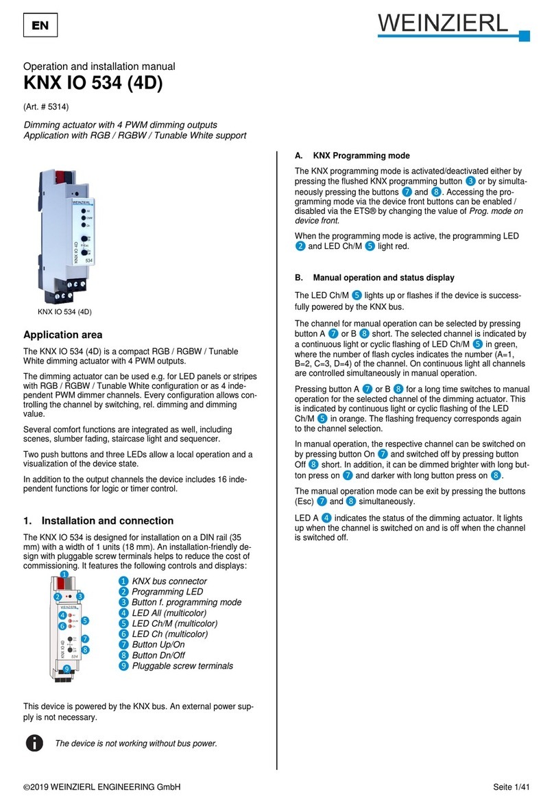
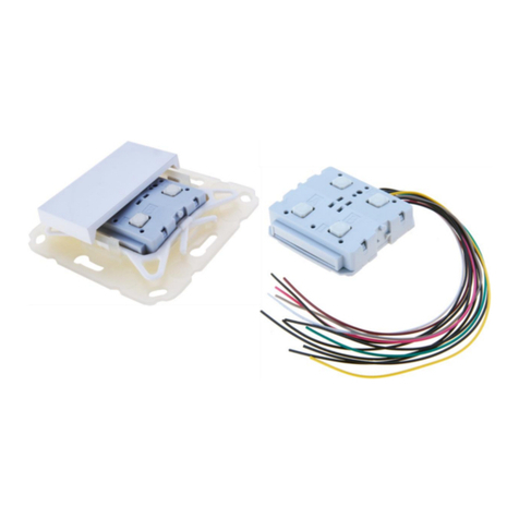
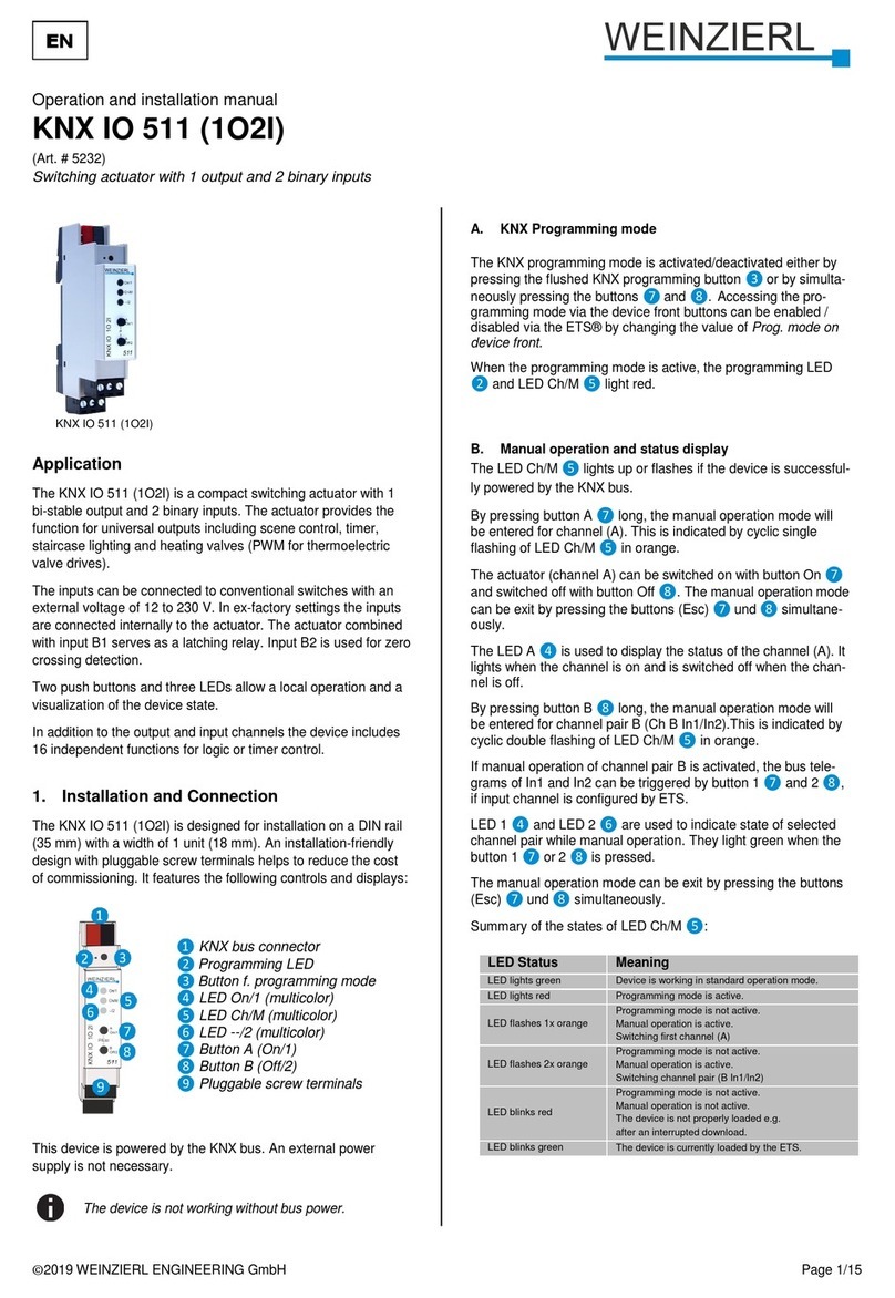
Weinzierl KNX IO 532 Specification sheet

©2019 WEINZIERL ENGINEERING GmbH Seite 1/16
Operation and installation manual
KNX IO 532 (1D1O)
(Art. # 5313)
Combined dimming/switching actuator with 1 LED dimming PWM output and 1 switching output
KNX IO 532 (1D1O)
Application area
The KNX IO 532 (1D1O) is a compact combined dim-
ming/switching actuator with 1 PWM dimming output for LEDs
and 1 bi-stable relay output.
The dimming actuator can be used e.g. for LED panels or
stripes. Besides controlling the dimmer by switching, rel. dim-
ming and dimming value, several optional functions are integrat-
ed, including scenes, automatic, slumber function or staircase
light.
The switching actuator provides the function for universal outputs
including scene control, timer, staircase lighting and heating
valves (PWM for thermoelectric valve drives).
Two push buttons and three LEDs allow a local operation and a
visualization of the device state.
In addition to the output channels the device includes 16 inde-
pendent functions for logic or timer control.
1. Installation and connection
The KNX IO 532 is designed for installation on a DIN rail (35
mm) with a width of 1 units (18 mm). An installation-friendly
design with pluggable screw terminals helps to reduce the cost
of commissioning. It features the following controls and displays:
This device is powered by the KNX bus. An external power
supply is not necessary.
The device is not working without bus power.
A. KNX Programming mode
The KNX programming mode is activated/deactivated either by
pressing the flushed KNX programming button ❸or by simulta-
neously pressing the buttons ❼and ❽. Accessing the pro-
gramming mode via the device front buttons can be enabled /
disabled via the ETS® by changing the value of Prog. mode on
device front.
When the programming mode is active, the programming LED
❷ and LED Ch/M ❺light red.
B. Manual operation and status display
The LED Ch/M ❺lights up or flashes if the device is successful-
ly powered by the KNX bus.
Pressing button A ❼long switches to manual operation of the
dimming actuator channel (channel A). This is indicated by
cyclic, one-time flashing of the LED Ch/M ❺in orange.
Pressing button B ❽long switches to manual operation of the
switching actuator channel (channel B). This is indicated by
cyclic, two-time flashing of the LED Ch/M ❺in orange.
In manual operation, the respective channel can be switched on
by pressing the button On ❼and switched off by pressing
button Off ❽short. In addition, the dimming actuator can be
dimmed brighter with long button press on ❼and darker with
long button press on ❽.
The manual operation mode can be exit by pressing the buttons
(Esc) ❼and ❽simultaneously.
LED A ❹indicates the status of the dimming actuator. It lights
up when the channel is switched on and is off when the channel
is switched off. Similarly, LED B ❻indicates the status of the
switching actuator (channel B).
Summary of the states of LED Ch/M ❺:
2. Reset to factory device settings
It is possible to reset the device to its factory settings:
Disconnect the KNX Bus connector ❶ from device
Press the KNX programming button ❸and keep it
pressed down
Reconnect the KNX Bus connector ❶ of device
Keep the KNX programming button ❸pressed for at
least another 6 seconds
A short flashing of all LEDs (❷❹❺❻) visualizes the
successful reset of the device to factory default settings.
LED Status
Meaning
LED lights green
Device is working in standard operation mode.
LED lights red
Programming mode is active.
LED flashes 1x orange
Programming mode is not active.
Manual operation is active, switching/dimming of
dimming actuator (channel A) possible.
LED flashes 2x orange
Programming mode is not active.
Manual operation is active, switching of switching
actuator (channel B) possible.
LED flashes red
Programming mode is not active.
Manual operation is not active.
The device is not properly loaded, e.g. after an
interrupted ETS download.
LED flashes green
The device is currently loaded by the ETS.
EN
❶KNX bus connector
❷Programming LED
❸Button f. programming mode
❹LED A/On (multicolor)
❺LED Ch/M (multicolor)
❻LED B/On (multicolor)
❼Button A/On
❽Button B/Off
❾Pluggable screw terminals

©2019 WEINZIERL ENGINEERING GmbH Page 2/16
3. Wiring scheme
Pluggable screw terminals
Channel A is on the upper terminal and channel B on the lower
terminal:
Upper terminal
The upper pluggable screw terminals ❾are used to control e.g.
LED panels or stripes.
The +12/24V connection of the used power supply unit is con-
nected to the right terminal at the upper screw terminals (12..24V
+), at the same time with the anode of the consumer. The ground
connection of the power supply unit is connected to the middle
terminal (12..24V -). The cathode of the consumer is connected
to the left terminal (Ch A Out -).
Lower terminal
The lower pluggable screw terminals ❾are used for the switch-
ing actuator, the left terminal pin Ch B Out is used as closer. The
central terminal pin Ch B !Out serves as opener. On the right
terminal pins Ch B Cm the common pin is contacted e.g. the
voltage to be switched.
4. Operating parameters of dimmer channel
Power dissipation
The dimming of luminaires is not possible without a certain
power loss in the dimmer. This power dissipation leads to a
heating of the device and depends on several factors. In addition
to the output of the connected lamps, the current dimming value
is also taken into account. Thus, the loss with the luminaire
switched off is almost zero except for the leakage current. Even
at 100%, the power loss is relatively low and can be traced back
to the contact resistance of the output.
Between 0 and 100% the switching losses caused by the PWM
are added. Overall, there is a maximum power loss in the upper
dimming range.
The rated power of 144W refers to the maximum permitted
ambient temperature for free installation. If there are other devic-
es next to the dimming actuator that emit heat, the power that
can be connected is reduced. Alternatively, the devices can also
be mounted at a small distance (approx. ½ TE = 9 mm). Suitable
spacers for the top-hat rail are available on the market for this
purpose.
Safety shutdown
The dimming actuator has an electronic fuse for overcurrent and
overtemperature. In both error cases, the output is switched off
and can be switched on again via a command if the error is no
longer present.
In addition, the device is also equipped with fuses against over-
current and overtemperature. This fuse stage protects connected
devices and surrounding materials against severe damage, but
leads to failure of the dimming actuator and can no longer be
reset.
5. ETS database
The ETS database (for ETS 4.2 ETS and 5) can be downloaded
from the product website of the KNX IO 532 (1D1O)
(www.weinzierl.de) or via the KNX online catalogue.
ETS parameter dialog
The following pages and parameters are visible in the ETS.
A. Description
This page shows the device description and the associated
wiring scheme.
B. General settings
Device name (30 Characters)
An arbitrary name can be assigned for the KNX IO 532 (1D1O).
The device name should be meaningful, e.g. „Living Room“. This
helps the clarity of the ETS project.
Ch A
Out- Ch A12..24V
+
Ch B
Out Ch B
!Out Ch B
Cm
-

©2019 WEINZIERL ENGINEERING GmbH Page 3/16
Send delay after bus power return
A send delay of telegrams after the return of the bus voltage can
be set via this parameter. In this case, telegrams from the device
are sent to the KNX bus in a delayed manner by the set time.
This results in a reduction of the bus load at a bus power return.
Other functions such as receiving telegrams of switching opera-
tions of the actuator are not affected by this parameter.
Prog. mode on device front
In addition to the normal programming button ❸the device
allows activating the programming mode on the device front
without opening the switchboard cover. The programming mode
can be activated and deactivated via pressing simultaneously
both buttons ❼and ❽.
This feature can be enabled and disabled via the parameter
“Prog. mode on device front”. The recessed programming button
❸(next to the Programming LED ❷) is always enabled and
not influenced by this parameter.
Manual operation on device
This parameter is used to configure the manual operation on the
device. The manual operation mode can be disabled or activated
(with or without time limitation). The time limit defines the dura-
tion until the automatic return from the manual operation mode
back into the normal operating mode.
The device is in normal operating mode when the manual control
is not active. In the manual operating mode, received switching
telegrams are ignored. When the manual operation mode is
terminated (after expiry of the time limit or manually), the last
state of the outputs remains, until a new switching telegram is
received again.
The following options are selectable:
Disabled
Enabled with time limit 1 min
Enabled with time limit 10 min
Enabled with time limit 30 min
Enabled without time limit
Heartbeat
Cyclic sending of values to the KNX-Bus, to indicate that the
device is operational. For the Cycle time values between 1 min
and 24h are selectable.
Alarm objects for error conditions
With this parameter, the following objects for the visualization of
error states become visible:
If an error condition is detected, the dimmer output switches off
and an ON telegram is sent via the respective object. The output
is disabled for the duration of the error state, if it is resolved, the
respective object sends an OFF telegram, and the dimmer can
be used normally again.
Overload is triggered from a load of 8A, overtemperature from a
measured temperature of 85°C in the load section. If no value is
received by the load section for longer than 3 seconds, the error
state "No supply voltage" is triggered.
PWM frequency
Here can be switched between 480Hz and 600Hz PWM fre-
quency.
C. Dimmer A: General
Name (30 Characters)
An arbitrary name can be assigned for the channel. However,
this should be clear and meaningful, this makes it easier to work
with the associated group objects, because the given name is
displayed there as a label. If no name is assigned, the group
objects are named „Dimmer A“.
Function
This parameter defines the functionality of the actuator, the
following options are selectable:
Disabled
Dimmer
When this functionality is selected, scene function, au-
tomatic mode, slumber and lock function are available.
In the "Dimmer" function, objects for switching on/off,
relative dimming, dimmer control via dimming and
RGB value can be configured. The parameter page
"Dimmer A: Dimmer" is displayed.
Staircase function
The parameter page "Dimmer A: Staircase function" is
displayed. Only the lock function is available here.
When a function is selected, the following parameters appear:
Send state
This parameter defines the behavior of the state objects:
Disabled
State objects are deactivated and not displayed.
Only on read
State objects send only on request.
On change
The switch object sends an OFF telegram when the
output value changes to 0%, an ON telegram when the
output value changes from 0% to a value greater than
0%. The value object transmits with a time interval of
at least 1 second if the value at the output has
changed by at least 1% or if a dimming process has
been completed.
Cyclic and on change
State objects send cyclically and on value change.
Group object
Type KNX
Size
Direction
GO 1 Heartbeat - Trigger
1.001
1 Bit
To KNX
Group object
Type KNX
Size
Direction
GO 2 Alarm - Overload
1.001
1 Bit
To KNX
GO 3 Alarm - Overtemperature
1.001
1 Bit
To KNX
GO 4 Alarm - No supply voltage
1.001
1 Bit
To KNX

©2019 WEINZIERL ENGINEERING GmbH Page 4/16
Group object
Type KNX
Size
Direction
GO 16 Dimmer A: Dimming output -
State On/Off
1.001
1 Bit
To KNX
GO 17 Dimmer A: Dimming output -
State value
5.001
1 Byte
To KNX
Time for cyclic state
With this parameter, the cycle time can be set, when “Cyclic and
on change“ is selected for sending state.
Behavior on bus power failure
The behavior of the output in the event of bus power failure can
be configured here.
The following options are selectable:
No reaction
Dim to value
A parameter for adjusting the value appears.
Behavior after bus power return
Here the behavior of the output after bus power return can be
configured. This behavior will be set after every device restart
(e.g. also on restart after ETS download).
The following options are selectable:
No reaction
Dim to value
A parameter for adjusting the value appears.
State like before bus power failure
Scene function
The scene function can be activated or deactivated here; it is
only available in the "Dimmer" operating mode. If this function is
activated, the parameter page "Dimmer A: Scene function"
appears for further configuration of scenes 1-16. The further
functionality is explained in section G.
Automatic mode
Automatic mode is only available in the "Dimmer" function. If this
mode is selected, the following objects become visible:
Group object
Type KNX
Size
Direction
GO 19 Dimmer A: Automatic Mode -
Activate
1.001
1 Bit
From/To
KNX
GO 20 Dimmer A: Autom. dimming abs. -
Set value
5.001
1 Byte
From KNX
When using automatic mode, the dimmer can be controlled via
object 20, e.g. for light control or daylight-dependent basic light-
ing.
In automatic mode, the dimmer can be manually overridden by
dimming on/off, dimming rel., dimming value, scene, slumber
function or sequencer. During manual override, values of object
20 are ignored, each manual override restarts the fallback time.
After the fallback time set in the parameter has elapsed, the
values received on object 20 are processed again.
Via object 19, the automatic can be switched on or off at any
time, it also serves as a state object for automatic mode.
Slumber function
The slumber function is only available in the "Dimmer" operating
mode. The slumber function offers 2 different fade times each for
switching on and off via object. If this function is activated, a new
parameter page appears, which is explained in section H.
Lock function
The lock function can be activated or deactivated here.
This function is available in both "Dimmer" and "Staircase func-
tion" operating modes. If this function is activated, a new param-
eter page appears for further configuration, which is explained in
Section I in more detail.
D. Dimmer A: Dimmer
Object Dimming on/off
For switching the dimmers, the following object is available, if it
has been activated via parameters:
Group object
Type KNX
Size
Direction
GO 11 Dimmer A: Dimming on/off -
Switch
1.001
1 Bit
From KNX
Behavior on ON telegram (when dimmer is off)
If the dimmer is switched off, this parameter can be used to
configure the behavior when switching on via object 11.
It is available:
No reaction
Dim to fix value
Dim to last value before switching off
Behavior on ON telegram (when dimmer is on)
If the dimmer is already switched on, this parameter can be used
to configure the behavior for a new ON telegram via object 11.
It is available:
No reaction
Dim to fix value
Dim to fix value if higher than actual
Dimming value on ON telegram
This value is activated by ON telegram via object 11 with suitable
parameterization.
Fade time on ON telegram
This fade time is active when an ON telegram is received. The
period refers to a complete dimming process of 0-100%.

©2019 WEINZIERL ENGINEERING GmbH Page 5/16
Behavior on OFF telegram
This parameter describes the behavior of the dimmer when an
OFF telegram is sent via object 11.
It is available:
No reaction
Dim to fix value
Dimming value on OFF telegram
This value is activated by OFF telegram via object 11 with suita-
ble parameterization.
Behavior on 2. OFF telegram
This parameter describes the behavior of the dimmer when a 2.
OFF telegram is received via object 11.
It is available:
No reaction
Switch off
The 2. OFF telegram must follow the 1. OFF telegram within 1
second in order to be evaluated. If the current brightness is
equal to or lower than the parameterized brightness for OFF
telegram, the device is already switched off by the 1. OFF tele-
gram.
Fade time on OFF telegram
This fade time is active when an OFF telegram is received. The
period refers to a complete dimming process of 0-100%.
Day/night switching
When using this function, the following objects are visible for
switching between day/night mode:
Group object
Type KNX
Size
Direction
GO 15 Dimmer A: Day/Night - Switch
1.001
1 Bit
From KNX
Day mode is triggered with an ON telegram on object 15, night
mode with an OFF telegram. After a restart, the device is in day
mode.
In addition, it can be determined when the values become active
after receiving a telegram on these objects, it is available:
Disabled
Switch on day/night telegram
Immediately after reception of day/night switching, it is
dimmed to the active value according to the last
switch-on/switch-off received via object 11.
Switch on next on/off telegram
The currently active value is not used until the next
switch on/off telegram via object 11.
There is a separate switch-on and switch-off value for night
mode in the parameters, in day mode the always visible values
are used.
Dimming value on ON telegram (night)
If the dimmer is in night mode, this value is activated by ON
telegram via object 11 and suitable parameterization.
Dimming value on OFF telegram (night)
If the dimmer is in night mode, this value is activated by OFF
telegram via object 11 and suitable parameterization.
Fade time for day/night switching
This fade time is only active if switching on day/night telegram is
used. If switching on next on/off telegram is used, the regular
fade time of the respective on or off telegram is active. The
period refers to a complete dimming process of 0-100%.
Object Dimming rel.
The following object is available for dimming using relative dim-
ming commands, if activated via parameters:
Group object
Type KNX
Size
Direction
GO 12 Dimmer A: Dimming rel. -
Brighter/Darker
3.007
4 Bit
From KNX
Minimal dimming value while dimming with object
This parameter can be used to set which minimum dimming
value can be achieved via relative dimming. If the current dim-
ming value is below the minimum value, the brightness cannot
be reduced via object 12.
Maximal dimming value while dimming with object
This parameter can be used to set which maximum dimming
value can be achieved via relative dimming. If the current dim-
ming value is above the maximum value, the brightness cannot
be increased via object 12.
Fade time while dimming brighter with object
This fade time is active when the brightness is increased by
relative dimming with object 12. The period refers to a complete
dimming process of 0-100%.
Fade time while dimming darker with object
This fade time is active when the brightness is decreased by
relative dimming with object 12. The period refers to a complete
dimming process of 0-100%.
Object Dimming value
The following object is used to control the dimmer via dimming
value if it has been activated via parameters:
Group object
Type KNX
Size
Direction
GO 13 Dimmer A: Dimming abs. - Set
value
5.001
1 Byte
From KNX

©2019 WEINZIERL ENGINEERING GmbH Page 6/16
Minimal dimming value for changing dimming value with
object
This parameter can be used to configure which minimum dim-
ming value can be reached via object 13. If a value below the
minimum value is received, the dimmer is controlled with the
minimum value. If a value >0% is set here, the following parame-
ter is also visible:
Switch off dimmer with telegram value 0%
Here it is to select whether the dimmer is switched off when a
value of 0% is received.
Minimal dimming value for changing dimming value with
object
This parameter can be used to configure which maximum dim-
ming value can be reached via object 13. If a value above the
maximum value is received, the dimmer is controlled with the
maximum value.
Fade time while dimming brighter with object
This fade time is active when the brightness is increased by
relative dimming with object 13. The period refers to a complete
dimming process of 0-100%.
Fade time while dimming darker with object
This fade time is active when the brightness is decreased by
relative dimming with object 13. The period refers to a complete
dimming process of 0-100%.
Object RGB value
To control the dimmer via RGB color value, the following object
is available, if activated via parameter:
Group object
Type KNX
Size
Direction
GO 14 Dimmer A: RGB color value - Set
value
232.600
3 Byte
From KNX
RGB value usage
Here it is set how a received RGB color value is to be processed:
Use red part
The 1. byte of the RGB value (red) is used to control
the brightness of the dimmer.
Use green part
The 2. byte of the RGB value (green) is used to control
the brightness of the dimmer.
Use blue part
The 3. byte of the RGB value (blue) is used to control
the brightness of the dimmer.
Use white (min. value of red, green, blue)
The smallest value of the 3 bytes is used to control the
brightness of the dimmer.
Use brightness (max. value of red, green, blue)
The largest value of the 3 bytes is used to control the
brightness of the dimmer.
Minimal value for changing color by object
This parameter can be used to configure which minimum dim-
ming value can be set via object 14. If a value below the mini-
mum value is received, the dimmer is controlled with the minimal
value.
Maximal value for changing color by object
This parameter can be used to configure which maximum dim-
ming value can be set via object 14. If a value above the maxi-
mum value is received, the dimmer is controlled with the maxi-
mum mal value.
Fade time while dimming brighter with object
This dimming time is active when the brightness is increased by
values received via object 14. The time period refers to a com-
plete dimming process of 0-100%.
Fade time while dimming darker with object
This dimming time is active when the brightness is decreased by
values received via object 14. The time period refers to a com-
plete dimming process of 0-100%.
E. Dimmer A: Staircase function
This parameter page can be used to implement a staircase
function with optional orientation light. The staircase function can
be overridden by the lock function. It has the following objects:
Group object
Type KNX
Size
Direction
GO 11 Dimmer A: Staircase function -
Trigger
1.010
1 Bit
From KNX
GO 15 Dimmer A: Day/Night - Switch
1.001
1 Bit
From KNX
Day mode is triggered with an ON telegram on object 15, night
mode with an OFF telegram. After a restart, the device is in day
mode.
Dimming value on switching on the staircase function (day)
This value is used in day mode when the staircase function is
switched on via ON telegram to object 11.
Dimming value on switching on the staircase function
(night)
This value is used in night operation when the staircase function
is switched on via ON telegram to object 11.
Fade time for switching on
This dimming time is active when the staircase function is
switched on via ON telegram to object 11. The period refers to a
complete dimming process of 0-100%.

©2019 WEINZIERL ENGINEERING GmbH Page 7/16
Delay time for staircase function
After the delay time has elapsed, the dimmer is dimmed to the
switch-off or orientation light value depending on the parameter
setting.
Reaction on ON telegram
This parameter determines the behavior after switching on the
staircase function via ON telegram on object 11: When "Switch
on" is set, the channel remains switched on after ON telegram
until the follow-up time is started via OFF telegram. In the setting
"Switch to delay time", the channel enters the delay time imme-
diately after the ON telegram.
Delay time retriggerable
If it is set that the delay time is started with ON telegram, this
parameter determines whether only the 1. ON telegram on object
11 starts the delay time, or also any further.
If it is set that the delay time is started with OFF telegram, this
parameter determines whether only the 1. OFF telegram on
object 11 starts the delay time, or also any other if the staircase
function is already in the delay time.
Orientation light after delay time
This parameter can be used to set whether the dimmer dims to
switch-off value or to orientation light at the end of the delay
time, as well as the duration of the orientation light.
It is available:
Disabled
1 s
2 s
5 s
10 s
30 s
1 min
2 min
5 min
10 min
20 min
30 min
1 h
2 h
Without time limit
Dimming value while orientation light
This value is dimmed to at the end of the delay time when orien-
tation light is used.
Fade time for orientation light
This fade time is active when the staircase function dims to
orientation light. The period refers to a complete dimming pro-
cess of 0-100%.
Reaction on OFF telegram
Here it can be set how the staircase function behaves in the
event of an OFF telegram. The following options are available:
Ignore
No reaction of the channel on OFF telegram
Switch off
Switch to switch-off value from the parameters
Switch to switch-off delay
The delay time is started with OFF telegram.
Switch to orientation light
The orientation light phase is started with OFF tele-
gram.
Switch to orientation light/switch off
With 1. OFF telegram the orientation light phase is
started, with 2. OFF telegram it is dimmed to switch-off
value.
Dimming value on switching off the staircase function (day)
This value is dimmed to in day mode if the staircase function is
switched off after the delay time or via OFF telegram on object
11.
Dimming value on switching off the staircase function
(night)
This value is dimmed to in night mode if the staircase function is
switched off after the delay time or via OFF telegram on object
11.
Fade time for switching off
This fade time is active when the staircase function dims to the
switch-off value. The period refers to a complete dimming pro-
cess of 0-100%.
F. Dimmer A: Dimming curve
This parameter page is used for fine adjustment of the dimmer to
different light sources.
All parameters on this page only affect the PWM value
of the output, not the dimming or output status value.
Dimming curve
Here it can be specified which PWM values are output by the
dimming outputs when the dimming channel has reached a
certain dimming value. The following options are available:
Linear
Logarithmic
User defined
Gamma
Gamma correction according to the formula:
Gamma is adjustable via parameter from 1.00 to 5.00.

©2019 WEINZIERL ENGINEERING GmbH Page 8/16
DALI
Function based on DALI with the formula:
Dimming output at x%
For the "Linear", "Logarithmic" and "User defined" dimming
curves, these values determine the PWM values of a dimming
output at the specified dimming value. Values between the
specified points are calculated and output linearly. As an exam-
ple, a dimming output with dimming curve "Logarithmic" behaves
according to the following graph:
The output values are fixed for the "Linear" and "Logarithmic"
dimming curves, and can be freely configured for the "User-
defined" curves.
If a dimming value of 0% is reached, the channel always
switches off.
Adjustment of channel
The PWM value of the calculated value by the dimming curve is
additionally scaled with this value.
G. Dimmer A: Scene function
If the scene function is activated, the following group objects
appear:
Group object
Type KNX
Size
Direction
GO 18 Dimmer A: Scene - Activ./Lrn.
18.001
1 Byte
From KNX
Fade time on activation of scene
Here the period can be set in which the received scene is
dimmed to. The period refers to a complete dimming process of
0-100%.
Scene 1-16
These parameters can be used to configure the reaction of the
channel when the respective scene is received.
It is available:
No reaction
Dimming value
The output is switched to the set dimming value if the
scene of the corresponding number was received.
Learnable
With the help of a scene control telegram, the current
state at the output for the respective scene can be
saved here. Thus the scene can be adapted by the
user without ETS download.
Number
With this parameter any scene number between 1 and 64 can be
assigned to the scene. No scene numbers may be assigned
twice.
H. Dimmer A: Slumber function
0%
10%
20%
30%
40%
50%
60%
70%
80%
90%
100%
0% 10% 20% 30% 40% 50% 60% 70% 80% 90% 100%
Gamma = 2 Gamma = 3,5 Gamma = 5
0%
10%
20%
30%
40%
50%
60%
70%
80%
90%
100%
0% 10% 20% 30% 40% 50% 60% 70% 80% 90% 100%
0%
10%
20%
30%
40%
50%
60%
70%
80%
90%
100%
0% 10% 20% 30% 40% 50% 60% 70% 80% 90% 100%

©2019 WEINZIERL ENGINEERING GmbH Page 9/16
If the slumber function is active, the following objects are visible:
Group object
Type KNX
Size
Direction
GO 21 Dimmer A: Slumber function -
Trigger
1.001
1 Bit
From KNX
Target value while switching on the slumber function
This value is reached by the channel after completion of the
dimming process after receiving an ON telegram via object 21.
Target value while switching off the slumber function
This value is reached by the channel after completion of the
dimming process after receiving an OFF telegram via object 21.
Fade time on 1. ON telegram (1. button press)
This fade time is used to dim to the target value for switching on
after the 1. button press. The period refers to a complete dim-
ming process of 0-100%.
Fade time on 2. ON telegram (2. button press)
This fade time is used to dim to the target value for switching on
after the 2. button press. The period refers to a complete dim-
ming process of 0-100%.
Fade time on 1. OFF telegram (1. button press)
This fade time is used to dim to the target value for switching off
after the 1. button press. The period refers to a complete dim-
ming process of 0-100%.
Fade time on 2. OFF telegram (2. button press)
This fade time is used to dim to the target value for switching off
after the 2. button press. The period refers to a complete dim-
ming process of 0-100%.
I. Dimmer A: Lock function
If the lock function is activated, the following objects are active:
Group object
Type KNX
Size
Direction
GO 22 Dimmer A: Lock - Activate
1.001
1 Bit
From KNX
GO 23 Dimmer A: Prior. dimming on/off -
Switch
1.001
1 Bit
From KNX
GO 24 Dimmer A: Prior. dimming rel. -
Brighter/Darker
3.007
4 Bit
From KNX
GO 25 Dimmer A: Prior. dimming abs. -
Set value
5.001
1 Byte
From KNX
If the lock was activated by object 22, other received telegrams
for dimmer, automatic mode, slumber, scene function and se-
quencer are not executed.
In addition to the lock object, 3 priority objects become visible
when the lock function is activated, with which the dimmer can
be controlled independently of the lock. This makes it possible to
set an initial state without affecting other functions.
Example of the priority objects:
In the case of events in public buildings or in restaurants, the
normal operation can be set into an inoperative state by the lock
group object. Thus it is possible to lock during the lecture or
concert, switches that are accessible to unauthorized persons, in
order to prevent unmeant switching. Nevertheless, the individual
lamps can controlled by use of the priority object without cancel-
ing the lock.
Polarity of object
This parameter defines, if the lock should be activated by receiv-
ing a 1 or by receiving a 0.
The following options are selectable:
Lock active on 1
Lock active on 0
Behavior on start
This parameter configures, which state the output should set, if
the lock activates.
The following options are selectable:
No reaction
Dim to value
A parameter for adjusting the value appears.
This output state can still be changed by the priority object.
Behavior at end
This parameter defines, which state the output should set, if the
lock deactivates.
The following options are selectable:
No reaction
Dim to value
A parameter for adjusting the value appears.
State before lock
This restores the original state before the lock was ac-
tivated. Telegrams received during the lock are ig-
nored.
State without lock
Here the state of the last received telegram is re-
stored. This takes into account the received telegrams
during the lock. Thus, when the lock is deactivated, the
last received telegram is set.

©2019 WEINZIERL ENGINEERING GmbH Page 10/16
J. Dimmer A: Sequencer
The sequencer can be used to create complex sequence pro-
grams consisting of up to 32 individual steps for the dimmer
channel. The individual steps can be activated under the follow-
ing starting conditions:
At a fixed time of day
After a waiting time from a previous step has elapsed
By on/off telegram
When receiving a parameterized scene number
When a step is activated, a value can be dimmed to or a scene
number can be sent, and a step or a whole sequence of steps
can be repeated cyclically.
The following objects are available for the general control of the
sequencer:
Group object
Type KNX
Size
Direction
GO 33 Dimmer A: Sequence suspend -
Suspend/Resume
1.001
1 Bit
From KNX
GO 34 Dimmer A: Sequence on/off -
Switch
1.001
1 Bit
From KNX
The following parameters determine the general behavior of the
sequencer:
Steps of sequencer
Number of steps (0...32) to be used
Resume sequence after man. operation
An activated sequence can always be interrupted or continued
via object 33 an ON telegram interrupts the sequence, and with
an OFF telegram it is continued.
A sequence is also interrupted after manual operation, i.e. after
commands for dimmer, automatic mode, slumber or scene func-
tion.
In addition, this parameter determines how an interrupted se-
quence can still be continued:
Only by object
The sequence can only be continued by object 33.
After off-time
The sequence is continued after the set off-time.
On next activated step
The sequence is continued with the next activated
step, the next step can be activated by object or time-
controlled.
Off-time
Only visible if the sequence is to be continued after off-time, with
this parameter the off-time can be configured.
Step after man. operation
This step is executed when resuming after manual operation, the
function of the set step is always executed, regardless of its
otherwise set starting conditions.
Polarity of object “Sequence on/off“
This parameter can be used to set the telegram value with which
the sequence can be switched on and off via object 34. If the
sequence is switched off, any further activation of a step is disa-
bled.
Behavior on switching on
Here it is determined how the sequencer behaves when
switched on by object 34:
No reaction
No function is executed, the sequencer waits for steps
to be activated.
Step x
The function of the step is executed (independent of
the other set start conditions of the step), the se-
quence is then continued according to its configuration
from this step onwards.
Switching on also reactivates a sequence interrupted by manual
operation.
Behavior on switching off
Here it is determined how the sequencer behaves when
switched off by object 34:
Complete actual step
If the sequencer is in a dimming process, it is complet-
ed.
Step x
The function of the step is executed (independent of
the other set start conditions of the step).
Stop immediately
If the sequencer is in a dimming process, it is stopped.
Apart from the set behavior when switching off, any further acti-
vation of a step after switching off is disabled until the sequencer
is switched on again by object 34.
Step 1-32:

©2019 WEINZIERL ENGINEERING GmbH Page 11/16
When a step is activated, its parameters for configuration ap-
pear.
In the text box at the top right with the content "Step x", you can
enter your own name for the step. This designation serves for
better orientation of the user and has no influence on the func-
tion of the step.
Start by time
This parameter is used to configure a temporal start condition of
the step.
Disabled
Start condition not used
Start at a fixed time of day
Here the time of day at which the step should start can
be entered. When using this start condition, the current
time must have been received via the following object:
Group object
Type KNX
Size
Direction
GO 5 Time of Day - Set
10.001
3 Byte
From KNX
If no valid time was received by object 5, all
start conditions at fixed times of day are not
active.
The time is continuously updated by the de-
vice through its internal timers, but compo-
nent tolerances always result in a deviation
from the actual time. Therefore, the current
time should be sent to the device by a pre-
cise timer at least twice a day in order to
keep the deviation as small as possible.
- Start after last trigger
Here you can specify the time interval to wait after the
previous activation before executing the step. This
start condition is not available for step 1.
Start time
Here either the time day or the waiting time can be specified for
the execution of the current step, if a timed start condition is
used.
Start by ON/OFF telegram
When using this start condition, a separate object is available for
each step:
Group object
Type KNX
Size
Direction
GO 35-66 Dimmer A: Sequence Step x
on/off - Switch
1.001
1 Bit
From KNX
An ON telegram to one of these objects activates the respective
step, the sequence is then continued according to its configura-
tion from this step onwards.
An OFF telegram also activates this step, but resets the se-
quence at the same time.
Start by scene number
When using this start condition, the following object becomes
visible:
Group object
Type KNX
Size
Direction
GO 31 Dimmer A: Sequence scene -
Activate step
18.001
1 Byte
From KNX
A telegram with the set scene on this object activates the respec-
tive step, the sequence is then continued according to its config-
uration from this step onwards.
All steps with this start condition are controlled by this object.
Action
When the step is activated, the configured function is executed,
the following functions are available for selection:
None
No function is executed, for example this can be used
to implement a switch-on delay for a sequence.
Start loop
The sequence continues from the selected step. Pa-
rameters for the initial step of the loop and the number
of loops become visible.
Send scene number
When using this function, the following object becomes
visible:
Group object
Type KNX
Size
Direction
GO 32 Dimmer A: Se-
quence Scene - Send
scene
18.001
1 Byte
To KNX
A parameter for the scene number to be sent becomes
visible. When the step is activated, this scene number
is sent via the object.
All steps send the scene number via this object, if this
function is used for the respective step.
Brightness
Parameters for brightness and fade time become visi-
ble. When this step is activated, the dimmer dims from
the current brightness value to the specified brightness
with the parameterized fade time. This time is related
to a complete dimming process of 0-100%.
K. Actuator B: General
Name (30 Characters)
An arbitrary name can be assigned for the channel. However,
this should be clear and meaningful, this makes it easier to work
with the associated group objects, because the given name is
displayed there as a label. If no name is assigned, the group
objects are named “Actuator B: …”.
Function
This parameter defines the functionality of the actuator.
The following options are selectable:
Disabled
Switch dimmer
Universal output
On/Off delay
Staircase function
Valve actuator (PWM for thermal servo)
If the actuator is not “Disabled”, the following parameters are
displayed:

©2019 WEINZIERL ENGINEERING GmbH Page 12/16
Behavior after bus power return
The behavior which is held at the output during the bus power
failure can be configured here.
The following options are selectable:
No reaction
Switch on
Switch off
Behavior after bus power return
Here the behavior of the output after bus power return can be
configured. This behavior will be set after every device restart
(e.g. also on restart after ETS download).
The following options are selectable:
No reaction
Switch on
Switch off
State like before bus power failure
Send state
This parameter defines the behavior of the state objects:
Disabled
State objects are deactivated and not displayed
Only on read
State objects send only on request
On change
State objects send on value change
Cyclic and on change
State objects send cyclically and on value change
Group object
Type KNX
Size
Direction
GO 78 Actuator B: Output - State
1.001
1 Bit
To KNX
GO 79 Actuator B: Valve actuator (PWM)
- State*
5.001
1 Byte
To KNX
* if valve actuator was selected
Time for cyclic state
Is selected state object “Cyclic and on change“, in this parameter
the cycle time can be set.
Lock function
With this parameter the lock function can be enabled. If this
functionality is activated, the associated group objects as well as
the parameter page “Actuator B: Lock function” are displayed for
further configuration. If the lock has been activated via the group
object "Lock", the received switching telegrams are not execut-
ed.
In addition to the lock object, there is also a priority object, which
can be switched independently of the lock. Thus, it is possible to
set an output state without affecting other functions.
Group object
Type KNX
Size
Direction
GO 75 Actuator B: Lock - Activate
1.001
1 Bit
From KNX
GO 76 Actuator B: Prior. output - Switch
1.001
1 Bit
From KNX
Example of the priority object:
In the case of events in public buildings or in restaurants, the
normal operation can be set into an inoperative state by the lock
group object. Thus it is possible to lock during the lecture or
concert, switches that are accessible to unauthorized persons, in
order to prevent unmeant switching. Nevertheless, the individual
lamps can controlled by use of the priority object without cancel-
ing the lock.
L. Actuator B: Lock function
Polarity of object
The following options are selectable:
Lock active on 1
Lock active on 0
Behavior on start
This parameter configures, which state the output should set, if
the lock activates.
The following options are selectable:
No reaction
Switch on
Switch off
This output state can still be changed by the priority object.
Behavior at end
This parameter defines, which state the output should set, if the
lock deactivates.
The following options are selectable:
No reaction
Switch on
Switch off
State before lock
This restores the original state before the lock was ac-
tivated. Switching telegrams received during the lock
are ignored.
State without lock
Here the state of the last received switching telegram
is restored. This takes into account the received
switching telegrams during the lock. Thus, when the
lock is deactivated, the last received switching tele-
gram is set.
Function (Switch dimmer)
In this operating mode, for example a dimmer power supply is
switched automatically. With a dimming value of 0% the relay
switches off, with a dimming value >0% it switches on. The
following parameter is also available:
Delay before switching off the relay
To avoid frequent switching off, a delay time before switching off
can be defined here.

©2019 WEINZIERL ENGINEERING GmbH Page 13/16
Function (Universal output)
If the universal output is selected on the parameter page "Actua-
tor B: General", the actuator can be used as a switching output.
A parameter for the scene function is also dis-played.
Group object
Type KNX
Size
Direction
GO 71 Actuator A: Output - Switch
1.001
1 Bit
From KNX
Scene function
With this parameter the scene function can be enabled or disa-
bled. If this functionality is enabled, the respective group object
as well as the parameter page "Actuator B: Scene function" are
displayed for further configuration of scenes 1-16.
Group object
Type KNX
Size
Direction
GO 72 Actuator A: Scene - Activ./Lrn.
18.001
1 Bit
From KNX
M. Actuator B: Scene function
Scene 1-16
These parameters can be used to configure the state, which is
set at the output when the respective scene is executed.
The following options are selectable:
No reaction
Switch on
Switch off
Learnable
By using a scene control telegram, the current state at
the output can be saved for the respective scene. This
allows the user to customize the scene without ETS
download.
Number
This parameter sets any scene number between 1 and 64 to the
scene. There must not configured any scene numbers twice.
Function (On/Off delay)
If the ON/OFF delay is selected on the parameter page "Actuator
B: General", delayed switching times can be con-figured. The
"Actuator B: On/Off Delay" parameter page is displayed for this
purpose.
Group object
Type KNX
Size
Direction
GO 71 Actuator B: Output - Switch
1.001
1 Bit
From KNX
N. Actuator B: On/Off delay
On delay time
The duration of the switch-on delay is configured in this parame-
ter.
Input -------1------------------0----------
Output -------|-T-1--------------0----------
Off delay time
The duration of the switch-off delay is configured in this parame-
ter.
Input -------1------------------0----------
Output -------1------------------|-T-0------
Retriggerable
If these parameters are activated, the respective delay time is
restarted upon receipt of the corresponding switching signal.
Function (Staircase function)
If the staircase function is selected on the parameter page "Ac-
tuator B: General", a group object for the staircase function
appears in addition to the normal switching object. Via the addi-
tional parameter page "Actuator B: Staircase function" this func-
tion can be configured.
Group object
Type KNX
Size
Direction
GO 71 Actuator B: Output - Switch
1.001
1 Bit
From
KNX
GO 73 Actuator B: Staircase function -
Trigger
1.010
1 Bit
From
KNX
O. Actuator B: Staircase function
Switch off time
The time for which the output is activated after an ON tele-gram
(object of the staircase function) has been received, can set in
this parameter.
Input -------1------------------0----------
Output -------1-T-0-------------------------
Retriggerable
This parameter can be used to set whether the follow-up time is
to be restarted when an ON telegram is received on the object of
the staircase function.

©2019 WEINZIERL ENGINEERING GmbH Page 14/16
Reaction on ‘OFF’ telegram
This parameter can be used to set whether an OFF telegram on
the object of the staircase function should be processed or ig-
nored.
Time for warning before switch off
The time between pre-warning and deactivation is configured, or
the pre-warning is deactivated with this parameter. If the pre-
warning time is longer than the actual follow-up time, no pre-
warning is carried out.
Time of interrupt
The pre-warning is indicated by a brief interruption (switch off ->
switch on). The duration of this interrupt is configured in this
parameter.
LED lamps often have a long follow-up time, in which
the lamp still lights even though it is already switched
off. With such lamps longer interrupt times must be set
to generate a "visible" interruption.
Function (Valve actuator)
The function valve actuator is foreseen to control thermoelectric
valve drives which are used for floor heating but also for radia-
tors. It maps the continuous position (0% - 100%) to an ongoing
On/Off sequence called PWM (pulse width modulation) signal.
If the valve actuator is selected on the parameter page "Actuator
B: General", a group object for the valve actuator appears in-
stead of the normal switching object. This allows the current
PWM at the output to be set via KNX (0% - 100%). An additional
parameter page "Actuator B: Valve actuator" appears for the
configuration of the valve actuator.
The received control value is saved automatically by the device,
to continue faultless after a possible bus power loss.
Group object
Type KNX
Size
Direction
GO 74 Actuator B: Valve actuator (PWM)
- Control value
5.001
1 Byte
From KNX
P. Actuator B: Valve actuator
Cyclic time (PWM)
The cyclic time of the PWM, which is used to control a servo
drive, is configured with this parameter. One cycle involves a
time range in which the output is switched on and one in which
the output is switched off. The cyclic time corresponds to the
period between two rising edges (state change at the output
from OFF to ON). The longer the flow of the heating circuit (tube
/ pipe length), the higher the cyclic time should be set.
Typical thermal servos require several minutes for a
100% valve change.
Maximum control value (PWM)
This parameter can be used to limit the maximum control value.
The control value is expressed in percent and de-fines the period
during which the output is switched on in one cycle.
Example:
Cyclic time = 10 Min.
Maximum control value (PWM) = 80 %
Maximal output state = ON - 8 min / OFF - 2 min
Stuck protection
With the stuck protection, it is intended to prevent the valve from
being damaged by corrosion or calcification, that it can no longer
be moved. In case stuck protection is enabled, this is only trig-
gered if the value is permanently 0 % or 100 %. On every other
control value the servo already moves, so there is no need for a
stuck protection.
Control value 0% Open servo for the set time
Control value 100%Close servo for the set time
In case the valve is not allowed to open, the stuck protection
must be disabled.
Execution time
If the stuck protection is activated, this parameter is used to set
the duration of the state change.
Monitoring interval
If the stuck protection is activated, this parameter sets the moni-
toring interval. If the state of the output remains un-changed for
this time, the lock protection is triggered.
Protection on missing control value
This parameter enables the protection function on missing con-
trol value telegrams. This is necessary in order to prevent un-
wanted and uncontrolled overheating or cooling down of the
room, when the control value is missing.
Protection takes effect, as soon as no telegrams are received
from the controller over a longer period of time. As soon as this
extended telegram pause has occurred, it can be assumed that
the corresponding controller has failed or the connection be-
tween the controller and the valve actuator has been interrupted.
Protection control value (PWM)
If the protection on missing control value is enabled, this pa-
rameter sets a protection control value. This configured PWM
value will set the output, if the protection is active.
As soon as telegrams from the controller are received again, the
protection control value (PWM) is overwritten by the received
value. The protection does not react again, until the waiting time
in the set monitoring interval is exceeded between individual
telegrams.
Monitoring interval
If the protection on missing control value is enabled, this pa-
rameter sets the monitoring interval. If no further telegram is
received by the device during this time, the protection function
takes effect.
Lock function (with valve actuator)
With this parameter the lock function can be disabled or enabled.
If this functionality is activated, the associated group objects as
well as the parameter page “Actuator 1: Lock function” are dis-
played for further configuration. If the lock has been activated via
the group object "Lock", the received switching telegrams are not
executed.
In addition to the lock object, there is also a priority object, which
can be used to set a control value independently of the lock.
Thus, it is possible to set an output PWM without affecting other
functions.

©2019 WEINZIERL ENGINEERING GmbH Page 15/16
When the lock is ended, the last received value (not priority
object) is represented as PWM at the output.
Group object
Type KNX
Size
Direction
GO 75 Actuator B: Lock - Activate
1.001
1 Bit
From KNX
GO 77 Actuator B: Prior. valve actuator
(PWM) - Control value
5.001
1 Byte
From KNX
Q. Actuator B: Lock function
Polarity of object
This parameter defines, if the lock should be activated by receiv-
ing a 1 or by receiving a 0.
The following options are selectable:
Lock active on 1
Lock active on 0
Behavior on start
This parameter defines, which behavior the output should repre-
sent, if the lock activates.
The following options are selectable:
No reaction
The PWM value remains as to begin of the lock func-
tion.
Value
When the lock is activated, a defined PWM value is
represented on the output.
Control value (PWM)
If a defined PWM value should be set to the output when the
lock is activated, this value can be set with this parameter.
R. Logic / Timer
Function 1 - 16
These channels contain additional functions such as timing and
logic. All these 16 additional functions are identical.
The following options are selectable:
Disabled
Timer
Logic
Function type (Disabled)
If the function type is set to "Disabled", no timer or logic specific
parameters and group objects are available.
Function type (Timer)
The timer-specific parameters and group objects are available.
Function type (Logic)
The logic-specific parameters and group objects are available.
These additional logic and timer functions can be
linked to one another by means of the associated
group objects. This also allows to create complex
structures. For this purpose, the output of a function is
set to the same group address as the input of the next
function.
S. Function 1 - 16 (Timer)
Function name (10 Characters)
The function name can be chosen freely.
The name is visible in the group object entry in the ETS soft-
ware. This makes it easier to work with the associated group
objects, because the given name is displayed there as a label.
Timer type (Switch-on delay)
A timer that switches ON after duration defined in
‘Delay time [s]’ parameter.
The output value can be inverted by parameter
‘Output’ (Not inverted / inverted).
Input -------1------------------0----------
Output -------|-T-1--------------0----------
Group object
Type KNX
Size
Direction
Timer - Switch-on delayed - Input
1.002
1 Bit
From KNX
Timer - Switch-on delayed - Output
1.002
1 Bit
To KNX
Timer type (Switch-off delay)
A timer that switches OFF after duration defined in
‘Delay time [s]’ parameter.
The output value can be inverted by parameter
‘Output’. (Not inverted / inverted)
Input -------1------------------0----------
Output -------1------------------|-T-0------
Group object
Type KNX
Size
Direction
Timer - Switch-off delayed - Input
1.002
1 Bit
From KNX
Timer - Switch-off delayed - Output
1.002
1 Bit
To KNX
Timer type (Switch-on and -off delay)
A timer that switches ON and OFF after duration defined in
‘Delay time [s]’ parameter.

©2019 WEINZIERL ENGINEERING GmbH Page 16/16
The output value can be inverted by parameter
‘Output’. (Not inverted / inverted)
Input -------1------------------0----------
Output -------|-T-1--------------|-T-0------
Group object
Type KNX
Size
Direction
Timer - Switch-on/off delayed - Input
1.002
1 Bit
From KNX
Timer - Switch-on/off delayed - Output
1.002
1 Bit
To KNX
Timer type (Impulse (Staircase))
Timer with impulse that - after being switched ON - automatical-
ly switches OFF after a defined duration defined in
‘Delay time [s]’ parameter.
The output value can be inverted by parameter
‘Output’. (Not inverted / inverted)
Input -------1------------------0----------
Output -------1-T-0-------------------------
Group object
Type
KNX
Size
Direction
Timer - Switch-impulse (staircase) - Input
1.002
1 Bit
From KNX
Timer - Switch-impulse (staircase) - Output
1.002
1 Bit
To KNX
Each timer can be stopped by sending the opposite val-
ue to its input group object.
For example:
An already started switch on timer can be stopped by
sending OFF (0) to its input group object.
T. Function 1 - 16 (Logic)
Function name (10 Characters)
The function name can be chosen freely.
The name is visible in the group object entry in the ETS soft-
ware. This makes it easier to work with the associated group
objects, because the given name is displayed there as a label.
Gate type (AND gate)
The output is triggered on (1), if both inputs are switched on (1).
Gate type (OR gate)
The output is triggered on (1), if one or both inputs are switched
on (1).
Gate type (XOR gate)
The output is triggered on (1), if the two inputs are not equal.
Gate type (NAND gate)
The output is triggered on (1), if one or both inputs are switched
off (0).
Gate type (NOR gate)
The output is triggered on (1), if both inputs are switched off (0).
Gate type (XNOR gate)
The output is triggered on (1), if both inputs are equal.
Gate type (INVERTER)
Input on (1) is converted into output off (0). Input off (0) is con-
verted into output on (1).
Group Object
Type KNX
Size
Direction
Logic - Gate input - Input
1.002
1 Bit
From KNX
Logic - Gate output - Output
1.002
1 Bit
To KNX
Group object
Type KNX
Size
Direction
Logic - Gate input A - Input
1.002
1 Bit
From KNX
Logic - Gate input B - Input
1.002
1 Bit
From KNX
Logic - Gate output - Output
1.002
1 Bit
To KNX
WARNING
The device must be mounted and commis-
sioned by an authorized electrician.
The prevailing safety rules must be heeded.
The device must not be opened.
For planning and construction of electric in-
stallations, the relevant guidelines, regulations
and standards of the respective country are to
be considered.
The device is a permanently connected
equipment: A readily accessible disconnect
device shall be incorporated external to the
equipment.
The installation requires a 16 A fuse for exter-
nal overcurrent protection.
The power rating is indicated on the side of
the product.
ETS4/5 Database
www.weinzierl.de/en/products/532/ets4
Datasheet
www.weinzierl.de/en/products/532/datasheet
CE Declaration
www.weinzierl.de/en/products/532/ce-declaration
Weinzierl Engineering GmbH
D-84508 Burgkirchen / Alz
Germany
www.weinzierl.de
2019/03/05
This manual suits for next models
2
Other Weinzierl Controllers manuals

Weinzierl
Weinzierl KNX IO 534 (4D) Specification sheet

Weinzierl
Weinzierl KNX TP Push Button 420 secure Specification sheet

Weinzierl
Weinzierl KNX IP LineMaster 760 Specification sheet

Weinzierl
Weinzierl KNX IO 511 Specification sheet

Weinzierl
Weinzierl KNX IO 510.1 secure Specification sheet

Weinzierl
Weinzierl 5374 Specification sheet