Rowe BC12 Technical manual

Validator Update Instructions for BC12 $1 - $20
The kit you have purchased includes the following items: metal validator slide plate, kit module in
black plastic box, parts kit. See figure 1.
1. Unplug the power cord from the wall and open the door of the changer. This kit is designed
for model BC12; figure 2.
2. Remove the bill transport by unplugging both connectors and sliding it forward and out of
the tracks.
3. Plug the kit’s jumper harness BCHARNJUMPER9 into the now open 9-position connector.
This is the male plug with the two short black wires found in the parts kit. The 6-position
connector is no longer used. See figure 3.
4. Remove the bill box from the stacker assembly. On dual stacker models remove both bill
boxes.
5. Remove the stacker assembly by unscrewing the two ¼” screws. It may be necessary to
hold the nuts under the assembly with a pair of pliers. Disconnect the harness from the
upper rear right hand side. The two ¼” screws that secure the stacker assembly base to the
cabinet must also be removed.
6. Slide the stacker assembly forward out of the changer. Replace the two screws and nuts.
7. Set the dip switches on the validator, the various possible settings are printed on
the module. Confirm the module is for a BC12.
8. Unplug the 9-position machine harness at the Coin Acceptor Assembly. See figure 4. Some
BC12 models were not originally purchased with the optional Coin Acceptor Assembly. If
this is the case, the machine harness that will be connected to the Module will be tucked
behind the hopper assembly.
9. Insert the 9-position harness from the new kit module into the open connector of the
machine harness. If you are accepting coins insert the 9 position female connector from the
module into the connector of the Coin Acceptor Assembly. If you are not accepting coins,
the 9-position plug with male pins from the module should remain unconnected.
10.Mount the kit module to the right side wall above the power input junction box using Velcro.
11.Unplug the 3-position main power harness from the power-input junction box. Plug the
harness from the kit module into the junction box. Plug the harness originally connecting to
the junction box into the new harness. See figure 4.
12.Run the remaining harness from the interface module down to the shelf level and then to
the left towards the Computer Control Center. It should be routed under the coin channel.
13.Slide the Computer Control Center all the way forward so that the header designated P2 is
accessible. It is at the rear of the board.
14.Unplug the 11 position straight connector at P2. Plug the new harness from the module into
P2, and then connect the harness originally at P2 into the new harness. See figure 5.
15.Slide the Computer Control Center back into place.
16.Set the dipswitches on the validator and mount it to the slide plate. Slide the validator
plate assembly down the tracks that originally secured the transport. It may be necessary
to loosen the 2 screws on the upper harness connector mounting plate. Attach the wiring
harness from the module with the long black connector validator. Note the position of the
two “keyed” pins. See figure 6.
17.Remove either of the 2 wires from the coin return switch; red or black. Slide the bare
terminal into the ¾” piece of shrink tube provided with the kit. Heat the tube to encase the
bare terminal.
18.Plug the power cord into the outlet and confirm the power switch is in the on position.
19.Insert several $1.00 dollar bills and then $5.00 dollar bills to confirm proper operation.
20.The update kit does not affect the programming of the payouts. The amount of coins
dispensed from each hopper is still programmed by turning “on” the multiplicative dip
switches on the control board.
NOTE: If the changer has the optional dual stacker assembly both bill boxes are removed in step 4.
For technical assistance we can be reached at 800 814-7756 9am-4:30pm EST
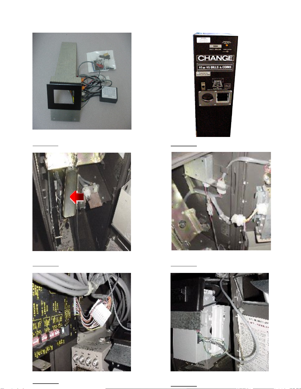
Figure 2
Figure 1
Figure 4
Figure 5
Figure 3
Figure 6
BC12
Table of contents
Other Rowe Bank Note Validator manuals


