4
number and serial number whenever you call
your Coinco Service Center for information or
service.
The first four digits of the bill acceptor serial
number indicate when the unit was built, which is
also the beginning of the warranty period:
• First two digits indicate week of
manufacture.
• Third and fourth digits indicate the year.
For example, Serial number 1508000123 indi-
cates the unit was manufactured in the 15th week
of 2008.
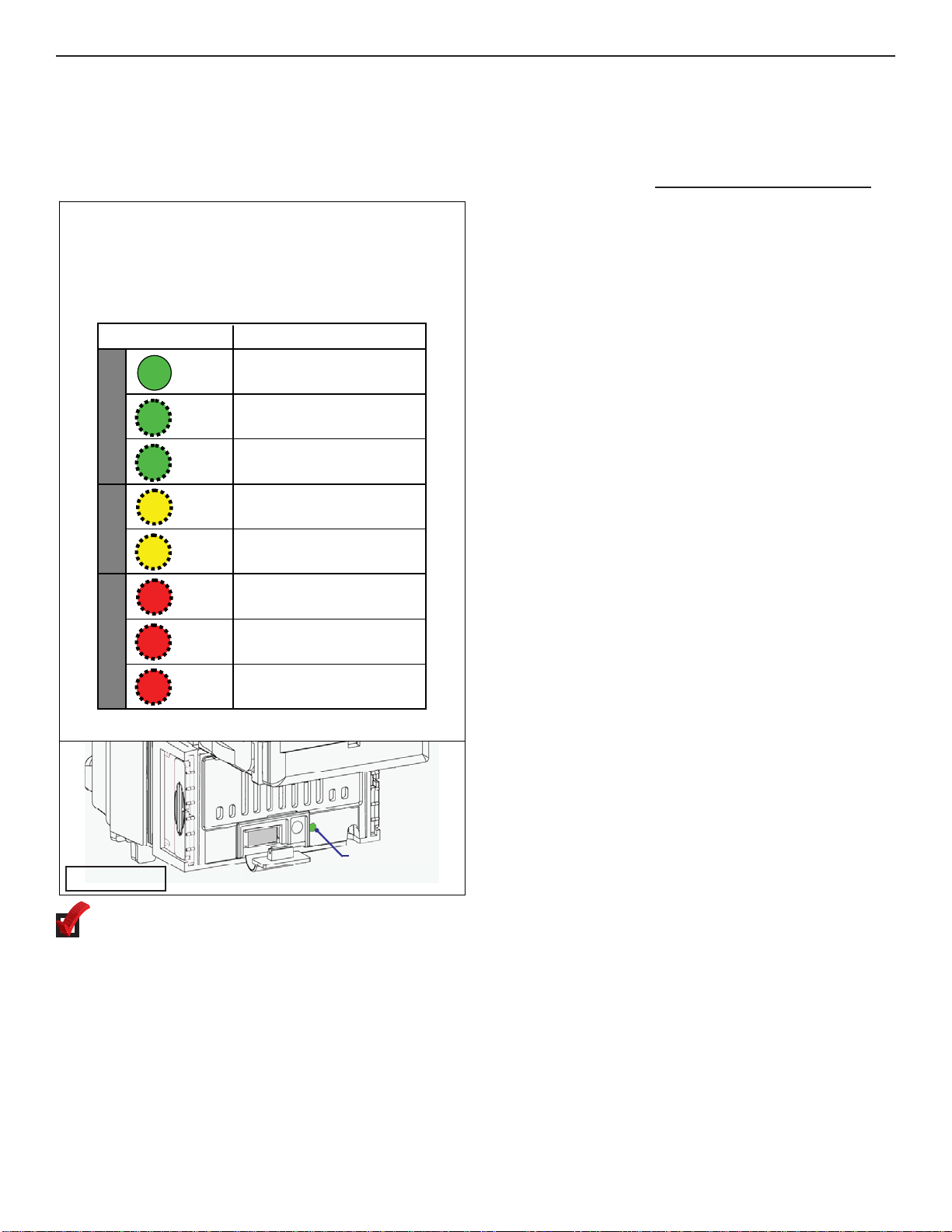
Icons
The following icons will guide you throughout the
manual. Each icon highlights an area you may
want to pay closer attention to.
Indicates a checklist type of process that
you can readily “check” as you proceed to
the next step.
Indicates a warning that you should
adhere to. It is often accompanied by
the words “DO NOT…”
Indicates a helpful hint or shortcut to
simplify the task.
Indicates where you can find additional
information regarding this specific topic.
Introduction
This manual contains information on installing,
operating and maintaining Coinco Vantage™
Series bill acceptors. This manual is intended for
owners, route operators and shop-level
technicians as a primary source of information.
Taking time to read this manual and become
familiar with the information will help you obtain
the best performance from your Vantage bill
acceptor.
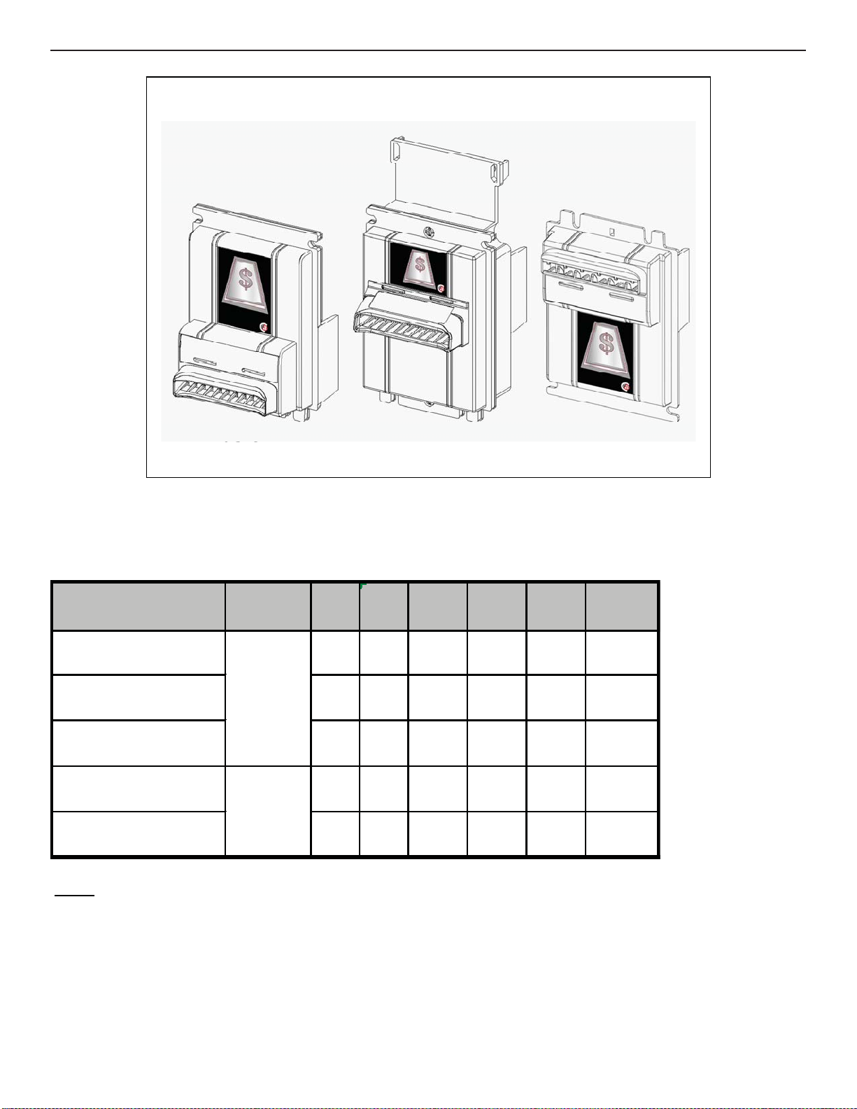
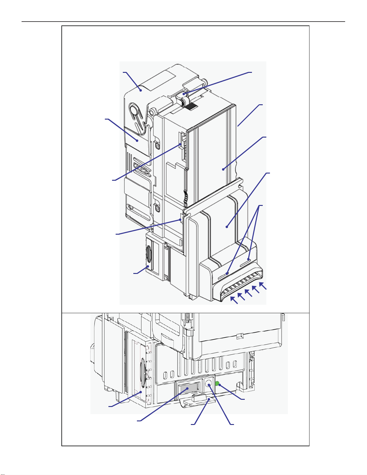
Product Overview and Features
The Vantage bill acceptor incorporates a wide
range of benefits, including:
• Quick-Release bezel speeds installation
and removal.
• Optional FlexStack™ bill box expands
from 200 bills to hold up to 500 bills. Fixed
note bill boxes are available with between
300 and 1100 note capacities.
• Illuminated bezel and status indicators
simplify setup and troubleshooting.
• Patented note path lockout provides high
security Level Three stringing and fishing
protection.
• Smart Bezel™ (optional) actively
communicates ability to accept $5 bills.
Basic operational features include:
•Bill widths accepted: 66mm (for Vantage
Vx6 models) or 72mm (for Vx7 models).
•Operating voltages: 110VAC, 24VAC,
34VDC.
•Communication Interface: MDB, Pulse,
Parallel, Vend Serial
•Mounting: Upstack or Downstack.
•Bezels: Basic, Slimline, or Downstack.
All versions feature standard Impulse
lighting. Smart Bezel™ option is available
for Basic and Slimline versions.
•Acceptance orientation: four ways.
•Coupons: Teach-n-Go field teach
capability.
For Your Records
A label indicating the bill acceptors model number
and serial number can be found on the left side
of the Vantage bill acceptor. Refer to the model
SECTION 1: GENERAL INFORMATION