8
5 IFB-828 Mechanical Assembly Parts
Qty Description Part Number
1 TRANSFORMER, TOROID 559002001
1 CONN .156 SP 3 POS 8800101838
1 CONN D HDWE KIT=KY 8800102463
1 A/C CORD/CONN 18GA 8800102668
1 A/C ENTRY MODULE 8800117313
9 CONN .100SP 2POS 24 8800127838
1 FUSE 1 AMP 5MMX 20M 8800129658
1 LED 5V GN PNL MNT W 8800131495
2 IDE PNL 7” 8800144463
8 KNOB POINTER 15MM 8800156636
8 KNOB 15MM ¼ SHFT 8800157458
8 LED GRN PNL MNT 8800191073
1 COVER 7” TOP/BTM 8800218428
8 KNOB CAP 15MM BLK 8800243720
1 PCB ASSY IFB POWER 90307094000
1 FRONT PANEL IFB828 90707094000
1 REAR PANEL IFB828 90807094000
1 BOTTOM PANEL 91007094000
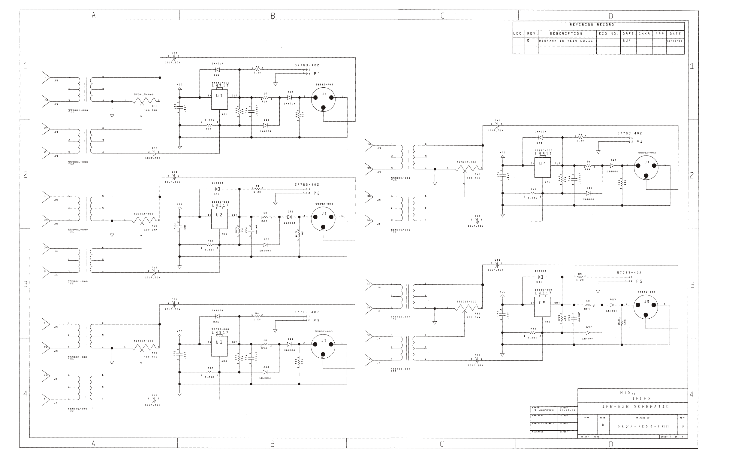
6 IFB-828 PC Board Electrical Parts
Ref Des Description Part Number
C1 CAPACITOR, EL, 1000 UF, 50V 51821-536
C2 CAPACITOR, CM, 0.1 UF, 50V 52676-613
C11 CAPACITOR, EL, 10 UF, 50V 51821-639
C12 CAPACITOR, CM, 0.1 UF, 50V 52676-613
C13 CAPACITOR, EL, 10 UF, 50V 51821-639
C21 CAPACITOR, EL, 10 UF, 50V 51821-639
C22 CAPACITOR, CM, 0.1 UF, 50V 52676-613
C23 CAPACITOR, EL, 10 UF, 50V 51821-639
C31 CAPACITOR, EL, 10 UF, 50V 51821-639
C32 CAPACITOR, CM, 0.1 UF, 50V 52676-613
C33 CAPACITOR, EL, 10 UF, 50V 51821-639
C41 CAPACITOR, EL, 10 UF, 50V 51821-639
C42 CAPACITOR, CM, 0.1 UF, 50V 52676-613
C43 CAPACITOR, EL, 10 UF, 50V 51821-639
C51 CAPACITOR, EL, 10 UF, 50V 51821-639
C52 CAPACITOR, CM, 0.1 UF, 50V 52676-613
C53 CAPACITOR, EL, 10 UF, 50V 51821-639
C61 CAPACITOR, EL, 10 UF, 50V 51821-639
C62 CAPACITOR, CM, 0.1 UF, 50V 52676-613
C63 CAPACITOR, EL, 10 UF, 50V 51821-639
C71 CAPACITOR, EL, 10 UF, 50V 51821-639
C72 CAPACITOR, CM, 0.1 UF, 50V 52676-613
C73 CAPACITOR, EL, 10 UF, 50V 51821-639
C81 CAPACITOR, EL, 10 UF, 50V 51821-639
C82 CAPACITOR, CM, 0.1 UF, 50V 52676-613
C83 CAPACITOR, EL, 10 UF, 50V 51821-639
D1 DIODE, BRIDGE, 2A, 1000V, BR810DF 558011-000
D11 DIODE, 1N4004, 400V 50745-005
D12 DIODE, 1N4004, 400V 50745-005
D13 DIODE, 1N4004, 400V 50745-005
D21 DIODE, 1N4004, 400V 50745-005
D22 DIODE, 1N4004, 400V 50745-005
D23 DIODE, 1N4004, 400V 50745-005
D31 DIODE, 1N4004, 400V 50745-005
D32 DIODE, 1N4004, 400V 50745-005
D33 DIODE, 1N4004, 400V 50745-005
D41 DIODE, 1N4004, 400V 50745-005
D42 DIODE, 1N4004, 400V 50745-005
D43 DIODE, 1N4004, 400V 50745-005
D51 DIODE, 1N4004, 400V 50745-005
D52 DIODE, 1N4004, 400V 50745-005
D53 DIODE, 1N4004, 400V 50745-005
D61 DIODE, 1N4004, 400V 50745-005
D62 DIODE, 1N4004, 400V 50745-005
D63 DIODE, 1N4004, 400V 50745-005
D71 DIODE, 1N4004, 400V 50745-005
D72 DIODE, 1N4004, 400V 50745-005
D73 DIODE, 1N4004, 400V 50745-005
D81 DIODE, 1N4004, 400V 50745-005
D82 DIODE, 1N4004, 400V 50745-005
D83 DIODE, 1N4004, 400V 50745-005
J1 CONNECTOR, RA XLR, M-3 59892-003
J2 CONNECTOR, RA XLR, M-3 59892-003
J3 CONNECTOR, RA XLR, M-3 59892-003
J4 CONNECTOR, RA XLR, M-3 59892-003
J5 CONNECTOR, RA XLR, M-3 59892-003
J6 CONNECTOR, RA XLR, M-3 59892-003
J7 CONNECTOR, RA XLR, M-3 59892-003
J8 CONNECTOR, RA XLR, M-3 59892-003
J9 CONNECTOR, RA SHIELDED, F-50 590121-002
P1 CONNECTOR, ST POLARIZED, 0.100, M-2 57763-402
P2 CONNECTOR, ST POLARIZED, 0.100, M-2 57763-402
P3 CONNECTOR, ST POLARIZED, 0.100, M-2 57763-402
P4 CONNECTOR, ST POLARIZED, 0.100, M-2 57763-402
P5 CONNECTOR, ST POLARIZED, 0.100, M-2 57763-402
P6 CONNECTOR, ST POLARIZED, 0.100, M-2 57763-402
P7 CONNECTOR, ST POLARIZED, 0.100, M-2 57763-402
P8 CONNECTOR, ST POLARIZED, 0.100, M-2 57763-402
P9 CONNECTOR, ST POLARIZED, 0.100, M-2 57763-402
P10 CONNECTOR, ST LOCKING, 0.156, M-3 57708-103
R1 RESISTOR, CF, 1.8K OHM, 5%, 1W 52154-629
R2 RESISTOR, CF, 1.2K OHM, 5%, 1/2W 52154-456
Ref Des Description Part Number