SECTION
1:
DESCRIPTIONAND SPECIFICATIONS
j)
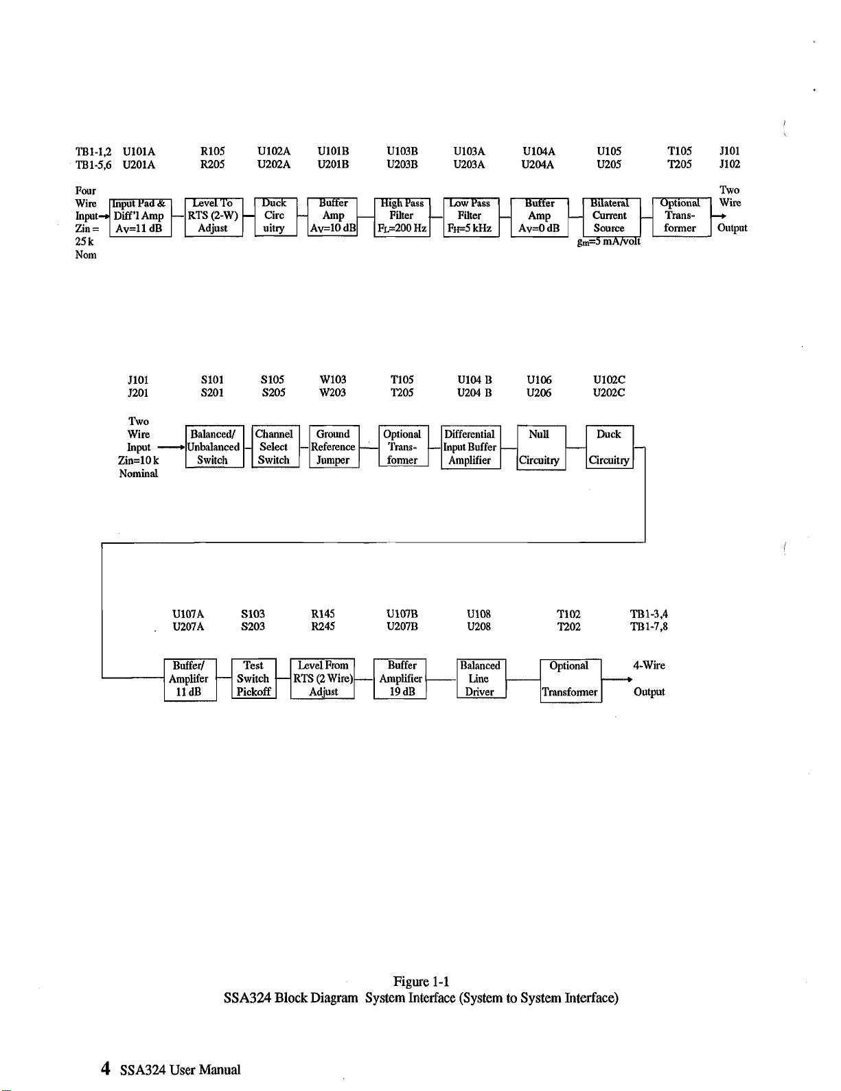
1.1
DESCRIPTION(See
Block
Diagram,
Figure
1-1)
,
TheModel SSA324
is
a System to System Adapter (or inter-
face). It interconnects the voice signals between different
intercom systems. In addition, it can optionallyinterconnect
"Calls" or tally signalsbetween systems. Each SSA324 in-
cludes two two-wire
to
four-wire converters. The four-wire
interfacecan deliver and accept high level signals such
as
those from the McCurdy intercom system.
An
SSA324 can
alsofunctionasatwo-wiretotwo-wireinterfaceby intercon-
necting the two individual interfaces at the four-wire level.
The SSA324carries two voice channelswhen used as adual
two-wiretofour-wireinterface,and onevoice channelwhen
functioningasa two-wire to two-wire interface.
A front panel channel select switch for each of the two
interfaces (A and B) will selectone of two, two-wire chan-
nels. For ClearCom use, theswitch will be in the Channel 2
.
position. For Audiocom use, a rear panel switch will select
balanced two-wire operation.
Front panel controls include
1)
adjustments for null, level,
ducking,2) switchesformonitoring and channelselect.
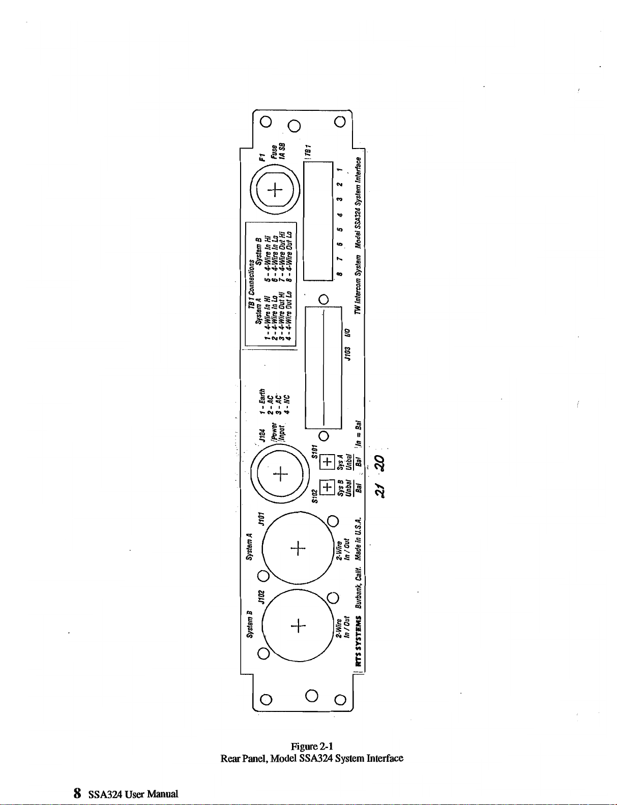
Rear
panel controls include balance/unbalance switches for
the two-wire connection of each interface.
Rear
panel con-
nectors include two
XLR3
connectors for two-wire, eight
terminals for two four-wire interconections, one
25
pin D
connector for duplicate four-wireconnections plus options
connections. Theterminals
are
useful forrapid fieldconnec-
tions. The
D
connector
aids
rapid replacement where mean-
time-to-repair
is
an issue
and
also
allowsoption strapping.
TheSSA324replaces theModel TWI224 andTWI222inter-
faces where powering from the intercom is not required.
Differencesbetween theModel TWI224
/
TWI222 interface
and
Model SSA324includethe following:
1)
The SSA324
is
self (locally) powered, the TWI224
/
TWI222 is usually
powered from the
TW
lineormay belocallypowered. 2) The
SSA324 has a maximum output at the four-wireoutput port
of +22 dBm, the TWI224
/
TWI222 maximum output is
9
dBm.
ConverterA's two-wireport is driven by an activebalanced
bilateral current source
(an
optional transformer may be
added). ConverterB's two-wireport is similarto Converter
A's.
Converter A's four-wireoutput
port
is driven by an active
balanced voltagelinedriver (or via an optionaltransformer).
A build-out resistor (about 33 ohms) in each leg of the
differential output maintains stability driving long cables.
Converter B's four-wireoutput port is similar to converter
A's.
The optional transformers can be used to provide higher
common mode voltage isolation between the four-wire sys-
tem(~)andthe two-wiresystems.
ConverterA's four-wireinputport isactivebalanced, biidg-
ing, ten thousand ohmsimpedance. Converter B's four-wire
input port
is
similar to converter A's.
(An
optional trans-
former
is
availablefor the four-wireinput(s).
Adjustable, 0
to
30
dB.
Toggles from one direction to the
other (thresholdis factory set). There
is
one adjustment for
interfaceAand onefor interfaceB. Each interfacehas depth
level adjustment(front panel).
Monitoring
Uses standard headset. Front Panel has six pin female
XLR
type headsetconnector.
Switchonfrontpanelactivatesthemonitoringfunction. User
uses headset microphoneor a built in oscillatorto adjust for
null in headsetearphones(orviaa built-in oscillatorwhich is
jumper selectedby ajumper on theprintedcircuitboard).
There
are
three null adjustments associated with each two-
wire port. These
are
resistive (medium), capacitive (high),
and inductive(low) nulls. Medium, High, and Low refers to
frequencyranges; medium centersabout
1
kilohertz,high,
3
kilohertz, low, 300hertz.
1.2.1
FUNCTIONAL SPECIFICATIONS
The Model SSA324 consists of two two-wire
to
four-wire
convertersin a singlepackage (converterAand converter
B).
If the two convertersareinterconnected,theModel SSA324
then functions as two-wire to two-wire converter. The
method of interconnection
is
as
follows: converterA's four-
wire output is connected to converter B's four-wire input;
converter A's four-wire input is connected to converter B's
output.
There are two level adjustments for interface
A
(to-from
two-wire)and two forinterfaceB (to-from two-wire).
SSA324 User Manual
5