manuals.online logo
Brands
  1. Home
  2. •
  3. Brands
  4. •
  5. RTS
  6. •
  7. Recording Equipment
  8. •
  9. RTS Zeus III User manual

RTS Zeus III User manual

LIT000381000 Rev A Copyright Bosch Security Systems 06/2009 Pg – 1
Quick Installation Guide for Zeus III Intercom Matrix – 90007843XXX
Parts List
Included Parts
A. Zeus III unit (p/n 90007843000)
B. Power Cord*, US, 115V (2)
(p/n 550024-013)
C. USB Cable (p/n 600091)
User Manual
(p/n 93507843000)
Warranty
(p/n 38110-387)
* Power Cord, European (550024-000)
Power Cord, UK, 13A (550024-005)
Zeus III unit without power cord (90007843-300)
Zeus III unit UK (90007843-200)
Zeus III unit EURO (90007843-100)
Instructions
To power on the Zeus III unit, do the following:
1. Connect the power cord connector end to the power
module on the rear side of the Zeus III (see Detail A).
2. Connect the power cord plug to an electrical outlet.
The Zeus III starts its power up sequence. See the
Zeus III user manual for the power up sequence
description.
Note: Repeat step 1 and step 2 for redundant power
supplies.
3. Configure the Zeus III in one of four (4) ways:
A. USB (page 1)
B. Serial (page 2)
C. Network (with Standard RJ-45 cable)(page 2)
D. Network (with RJ-45 Crossover cable)
(page 3) (Used when configuring the Zeus III for
the first time with no serial or USB port available)
USB Configuration
Note: If you are configuring a USB connection for the first
time, you must manually navigate to the USB drivers at
C:\Telex\AZedit\USB.
1. Attach the supplied USB cable to the USB
Connector located on the front of the Zeus III.
2. Attach the other end of the USB cable to any USB
connector on the computer with AZedit loaded on it.
3. In AZedit, from the Options menu, select
Communications.
The Communications window appears.
4. Select the USB radio button.
5. Click OK.
The Zeus III is configured to connect to AZedit via
USB.
LIT000381000 Rev A Copyright Bosch Security Systems 06/2009 Pg – 2
Serial Configuration
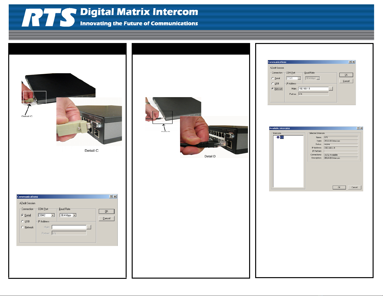
1. Attach the male end of the serial cable to the
Trunk/To PC connector on the rear side of the
Zeus III.
2. Attach the female end of the serial cable to any
available serial connector on the computer with
AZedit loaded on it.
3. In AZedit, from the Options menu, select
Communications.
The Communications window appears.
4. Select the Serial radio button.
5. Click OK.
The Zeus III is configured to connect to AZedit
serially.
Ethernet Configuration – Standard RJ-45
Note: The straight RJ-45 cable assembly cannot be
directly connected to the AZedit computer. It
can only be used with a router or switch
connected to the network.
1. Attach the standard RJ-45 Ethernet cable to your
existing IP network using a network router or switch.
2. Attach the other end of the RJ-45 cable to the
Ethernet connector located on the rear of the Zeus III.
Note: By default, Zeus III is shipped with the IP
Address 192.68.0.9 and the Network Mask
255.255.0.0. To change the IP Address,
initially you must connect either serial or a
USB cable. See “Initial IP Address
Configuration” on page 3.
3. Click Apply.
The IP Address, Network Mask, and Gateway Address
are changed.
4. Click Close.
The Ethernet Settings window closes.
5. From the Options menu, select Communications.
The Communications window appears.
6. Select the Network radio button.
7. Click the browse button.
The Available Intercom window appears.
8. From the Intercoms list field, select the Zeus III
intercom you want to connect to.
9. Click OK.
The Available Intercoms window closes.
10. Click OK.
The Communications window closes. The Zeus III
is configured for Ethernet operation with a
standard RJ-45 cable.
LIT000381000 Rev A Copyright Bosch Security Systems 06/2009 Pg – 3
Ethernet Configuration – RJ-45 Crossover
By default, the Zeus III is shipped with the IP Address
192.168.0.9. and the network Mask is 255.255.255.0. To
change the IP Address initially, you must connect either
serially or via USB.
1. Attach one end of the RJ-45 crossover cable to the
Ethernet connector located on the rear of the Zeus
III unit.
2. Attach the other end of the RJ-45 crossover cable
to the Ethernet port of the computer with AZedit.
3. In AZedit, from the Options menu, select Ethernet
Setup.
The Ethernet Setup window appears.
4. From the Options menu, select Communications.
The Communications window appears.
5. Select the Network radio button.
6. Click OK.
The Communications window closes. The Zeus III
is configured for Ethernet operation with a
standard
RJ-45 cable.
Initial IP Address Configuration
1. Connect to the PC with AZedit via USB or Serial
cable.
2. In AZedit, from the Options menu, select Ethernet
Setup.
The Ethernet Setup window appears.
3. In Netmask field, enter the Netmask Address for the
Zeus III, if needed.
4. In the Gateway field, enter the Gateway Address for
the Zeus III, if needed.
5. Click Save.
The configuration is saved.
6. Remember to send your changes to the Matrix. To
send changes to the matrix, from the edit menu, select
Send Changes.
LIT000381000 Rev A Copyright Bosch Security Systems 06/2009 Pg – 4
Connectors
Front USB Standard Type B
Pin Function
1V_BUS
2D-
3D+
4 GND
Party Line (2) 3-Pin Female XLR
Pin RTS CH1 RTS CH2 Audiocom
(balanced) Clear Com
(unbalanced)
1 Common Common Common Common
2 Audio
+CALL
signal
CH1 Audio
Low +Call
3 Audio
+CALL
signal
CH1 Audio
High +Call Audio + DC
Call
Rear Keypanel Port (32) RJ–45(Cat5)
Pin Function
1N/C
2 RS485 Data -
3 Audio Out +
4 Audio In +
5 Audio In -
6 Audio Out -
7 RS485 Data +
8N/C
Trunking/To PC Connection
Pin Function
1 RS485 Data - – Trunking
2 RS232 RX – Serial Data
3 RS232 TX – Serial Data
4N/C
5 GND – Serial Data
6 RS485 Data + – Trunking
7 GND
8N/C
9N/C
GPI DB-25 Female
Pin Function
1 GPI Input #1
2 GPI Input #2
3 GPI Input #3
4 GPI Input #4
5 GPI Input #5
6 GPI Input #6
7 GPI Input #7
8 GPI Input #8
9 GND
10 GND
11 GND
12 GND
13 GND
14 GPI Output #1
15 GPI Output #2
16 GPI Output #3
17 GPI Output #4
18 GPI Output #5
19 GPI Output #6
20 GPI Output #7
21 GPI Output #8
22 GND
23 GND
24 GND
25 GND

Other manuals for Zeus III

1

This manual suits for next models

1

Other RTS Recording Equipment manuals

RTS DSI 2008 User manual

RTS

RTS DSI 2008 User manual

RTS WKP-8 User manual

RTS

RTS WKP-8 User manual

RTS SSA-324 User manual

RTS

RTS SSA-324 User manual

RTS KP-32 User manual

RTS

RTS KP-32 User manual

RTS KP 32 CLD User manual

RTS

RTS KP 32 CLD User manual

RTS OMI-2 User manual

RTS

RTS OMI-2 User manual

RTS 9V2 User manual

RTS

RTS 9V2 User manual

RTS IFB-828 User manual

RTS

RTS IFB-828 User manual

RTS OMNEO User manual

RTS

RTS OMNEO User manual

RTS SIP-ISDN Mounting instructions

RTS

RTS SIP-ISDN Mounting instructions

RTS TIF-2000A User manual

RTS

RTS TIF-2000A User manual

RTS OMNEO OEI-2 User manual

RTS

RTS OMNEO OEI-2 User manual

Popular Recording Equipment manuals by other brands

M-Audio M-Track Eight user guide

M-Audio

M-Audio M-Track Eight user guide

Lumel N30B TYPE user manual

Lumel

Lumel N30B TYPE user manual

Raven SCS 440 Installation & service manual

Raven

Raven SCS 440 Installation & service manual

Fostex APPENDIX Operation manual

Fostex

Fostex APPENDIX Operation manual

DMP Electronics 472 Inovonics installation guide

DMP Electronics

DMP Electronics 472 Inovonics installation guide

Barco R9828120 manual

Barco

Barco R9828120 manual

Extron electronics DMP 64 Setup guide

Extron electronics

Extron electronics DMP 64 Setup guide

PRESONUS DEQ 624 datasheet

PRESONUS

PRESONUS DEQ 624 datasheet

SEW-Eurodrive DFP21B manual

SEW-Eurodrive

SEW-Eurodrive DFP21B manual

M2SYNTH SV VCF 112 Assembly instructions

M2SYNTH

M2SYNTH SV VCF 112 Assembly instructions

Fostex VF160EX Operation manual

Fostex

Fostex VF160EX Operation manual

Roland V-studio VS-2480 Guide

Roland

Roland V-studio VS-2480 Guide

Roli Seaboard RISE 25 quick start guide

Roli

Roli Seaboard RISE 25 quick start guide

Steinberg CI2 Benutzerhandbuch

Steinberg

Steinberg CI2 Benutzerhandbuch

Fostex 8346 Operation manual

Fostex

Fostex 8346 Operation manual

Dometic WAECO MagicSpeed CBI 150 Installation and operating manual

Dometic

Dometic WAECO MagicSpeed CBI 150 Installation and operating manual

PI 2 Design PI2AES-LITE Hardware reference manual

PI 2 Design

PI 2 Design PI2AES-LITE Hardware reference manual

mikroElektronika 4-20mA R click quick start guide

mikroElektronika

mikroElektronika 4-20mA R click quick start guide

manuals.online logo
manuals.online logoBrands
  • About & Mission
  • Contact us
  • Privacy Policy
  • Terms and Conditions

Copyright 2025 Manuals.Online. All Rights Reserved.