Ruck FFH 125 EC 10 User instructions

Assembly and Operating Manual
Compact Supply air unit
English
00
137771
www.ruck.eu
FFH 125 EC 10
FFH 150 EC 10
FFH 160 EC 10
FFH 200 EC 10
FFH 250 EC 10
FFH 315 EC 10
FFH...EC,

mzf_pb_03b_en print 25.09.2018
ruck Ventilatoren GmbH Max-Planck-Str. 5 D-97944 Boxberg-Windischbuch Tel. +49 7930 9211-0 Fax. +49 7930 9211-150 [email protected]
Information updated: print 25.09.2018
We reserve the right to make changes
The data specied above only serve to describe the product.
No statements concerning a certain condition or suitability for
a certain application can be derived from our information. The
information given does not release the user from the obligati-
on of own judgment and verication.
It must be remembered that our products are subject to a
natural process of wear and aging.
This document, as well as the data, specications and other
information set forth in it, are the exclusive property of ruck
Ventilatoren GmbH.
It may not be reproduced or given to third parties without its
consent.
Auf der Titelseite ist eine Beispielkonguration abgebildet.
The product supplied may therefore differ from the illustration.
The original manual has been produced
in the German language.
ruck Ventilatoren GmbH Max-Planck-Str. 5 D-97944 Boxberg-Windischbuch Tel. +49 7930 9211-0 Fax. +49 7930 9211-150 [email protected]

English
Contents
Assembly and Operating Manual
1. Important information ...............................................................................4
1.1. Rules and regulations ......................................................................4
1.2. Guarantee and liability .....................................................................4
2. General safety instructions ......................................................................4
2.1. Intended use ....................................................................................4
2.2. Improper use ....................................................................................5
2.3. Personnel qualications ...................................................................5
2.4. Safety instructions in this manual.....................................................5
2.5. Adhere to the following instructions .................................................6
2.5.1. General instructions .........................................................................6
2.5.2. During installation.............................................................................6
2.5.3. During commissioning......................................................................6
2.5.4. During operation...............................................................................6
2.5.5. During cleaning ................................................................................6
2.5.6. During maintenance and repair........................................................6
2.5.7. Disposal ...........................................................................................6
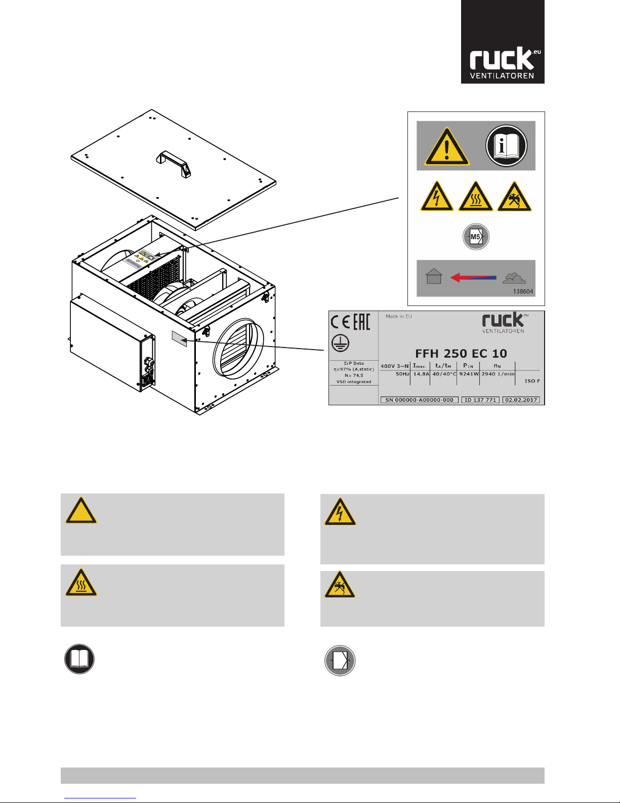
2.6. Safety labels on the product.............................................................7
3. Delivery contents.......................................................................................7
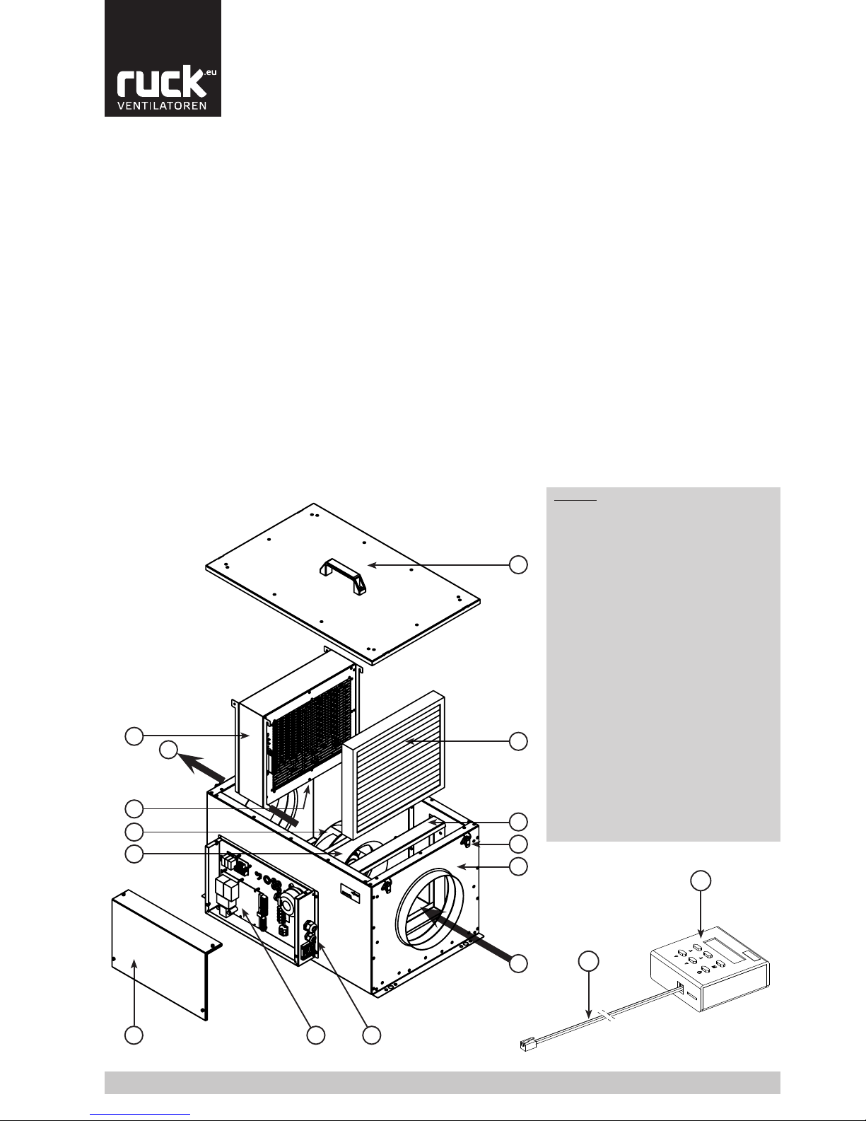
4. Product and Performance description ....................................................8
4.1. Device description............................................................................8
5. Transport and storage...............................................................................9
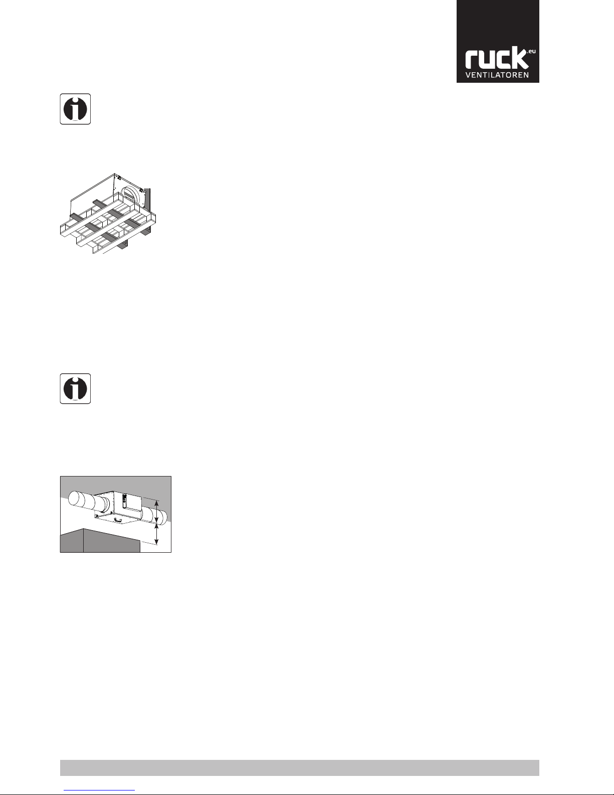
6. Assembly....................................................................................................9
6.1. Permitted installation positions.......................................................10
6.2. Operating limits ..............................................................................10
7. Electrical connection ..............................................................................10
7.1. Overcurrent protection ...................................................................11
7.2. Wiring diagrams .............................................................................12
7.3. Connection EC-extract fan .............................................................12
8. Commissioning........................................................................................13
9. Operation..................................................................................................14
9.1. Control unit.....................................................................................14
9.1.1. Adjustment of the control unit parameter .......................................15
9.2. Menu management ........................................................................16
9.3. Menu functions...............................................................................17
9.3.1. Time / Time switch..........................................................................17
9.3.2. Operating variables Menu ..............................................................18
9.3.3. Parameter settings Menu ...............................................................19
9.4. Additional functions ........................................................................20
10. Maintenance and repair ..........................................................................20
10.1. Important notes ..............................................................................20
10.2. Cleaning and care ..........................................................................21
10.3. Maintenance...................................................................................21
10.3.1. Air lter...........................................................................................21
10.3.2. Changing the battery .....................................................................22
11. Expansionandreconguration..............................................................22
12. Dismantling and disposal .......................................................................22
12.1. Disassembling the product.............................................................22
12.2. Disposal .........................................................................................22
13. Troubleshooting.......................................................................................23
13.1. Low-current fuses...........................................................................23
13.2. Fault diagnosis chart ......................................................................24
13.3. Possible operating faults. ...............................................................24
14. Technical data..........................................................................................25
15. Appendix ..................................................................................................26
15.1. List of parameters ..........................................................................26
15.2. Wiring diagrams .............................................................................27
3
www.ruck.eu

English
1. Important information
This manual contains important information on the safe and appropriate assembly, transport, commissio-
ning, operation, maintenance, disassembly and simple troubleshooting of the product.
The product has been manufactured according to the accepted rules of current technology. There is, ho-
wever, still a danger of personal injury or damage to equipment if the following general safety instructions
and the warnings before the steps contained in these instructions are not complied with.
• Read these instructions completely and thoroughly before working with the product.
• Keep these instructions in a location where they are accessible to all users at all times.
• Always include the operating instructions when you pass the product on to third parties.
1.1. Rules and regulations
1.2. Guarantee and liability
Also observe the generally applicable, legal or otherwise binding regulations of the European or
national legislation and the rules for the prevention of accidents and for environmental protection
applicable in your country.
ruck products are made to the highest technical standards in accordance with the generally reco-
gnized rules of the profession. They are subject to constant quality control and meet the relevant
requirements when delivered. Because the products are being constantly developed, we reserve the
right to make changes to the products at any time and without prior announcement. We do not accept
any liability for the correctness or completeness of this installation and operating manual.
Thewarrantyonlyappliesto thedelivered conguration.The warrantywill notapply ifthe
product is incorrectly assembled or handled or not used as intended.
2. General safety instructions
2.1. Intended use
• Exclusively use ruck Ventilatoren in good technical order and condition.
• Check the product for visible defects, for example cracks in the housing or missing rivet, screws and
covers.
• Only use the product within the performance range provided in the technical data.
• Protection against contact and being sucked in and safety distances should be provided in accor-
dance with DIN EN ISO 13857.
• Generally prescribed electrical and mechanical protection devices are to be provided by the client.
• Safety components must not be bypassed or put out of operation.
• The product may be operated by personnel with limited physical, sensory or mental capacities only if
they are supervised or have been instructed by responsible personnel.
• Children must be kept away from the product.
Planners, plant engineers and operators are responsible for ensuring that the product is installed and
operated correctly.
The ruck fan is a component in terms of the machine directive 2006/42/EC (partly completed ma-
chinery). The product is a not ready-for-use machine in terms of the machine directive. It is intended
exclusively for installation in a machine or in ventilation equipment and installations or for combina-
tion with other components to form a machinery or installation. The product may be commissioned
only if its integrated in the machinery/system for which it is designed and the machinery/system fully
complies with the EC machinery directive.
Observe the operating conditions and performance limits specied in the technical data.
ruck ventilation products can be used to provide:
• Clean, dry air (no condensation) and non-aggressive gases with a maximum density of 1.3 kg/
m³.
• The medium and room temperatures and the humidity range given in the technical data and on
the rating plate.
Intended use includes having read and understood these instructions, especially chapter 2
“General safety instructions”.
4
Tel. +49 7930 9211-0 Fax. +49 7930 9211-150

English
Any use of the product other than described in chapter “Intended use” is considered as improper.
Also note the following points, which are improper and dangerous:
• Delivery of explosive and flammable media or operation in potentially explosive atmospheres.
• Delivery of aggressive and abrasive media.
• Delivery of media containing dust or grease.
• Installation outside without any protection against the weather.
• Installation in wet areas.
• Operation without the duct system.
• Operation with closed air connections.
2.2. Improper use
Assembly, commissioning and operation, disassembly and service (including maintenance and re-
pair) require basic mechanical and electrical knowledge, as well as knowledge of the appropriate
technical terms.
In order to ensure operating safety, these activities may therefore only be carried out by qualied
technical personnel or a person under the direction and supervision of qualied personnel. Quali-
ed personnel are those who can recognize possible hazards and institute the appropriate safety
measures due to their professional training, knowledge, and experience, as well as their understan-
ding of the relevant conditions pertaining to the work to be done. Qualied personnel must observe
the rules relevant to the subject area.
2.3.Personnelqualications
In this manual, there are safety instructions before the steps whenever there is a danger of personal
injury or damage to the equipment. The measures described to avoid these hazards must be obser-
ved.
2.4. Safety instructions in this manual
Safety instructions are set out as follows:
Safety sign (warning triangle) - Draws attention to the risk
• Type of risk - Identies the type or source of the hazard.
»Consequences - Describes what occurs when the safety instructions are not complied with.
→Precautions - States how the hazard can be avoided.
General warning!
Indicates possible hazardous situations. Failure to observe the warnings
may result in personal injury and / or damage to property.
Electricity warning (hazardous voltage)!
Indicates possible hazards due to electricity. Failure to observe the war-
nings may result in death, injury and/or damage to property.
Hot surface warning!
Indicates possible hazards due to high surface temperatures. Failure
to observe the warnings may result in personal injury and/or damage to
property.
Crushingofngerswarning!
Indicates possible hazards due to moving and rotating parts. Failure to
observe the warnings may result in personal injury.
Overhead load warning!
Indicates possible hazards due to overhead loads. Failure to observe the
warnings may result in death, injury and/or damage to property.
Important instructions follow!
Instructions for safe, optimum use of the product.
Safety sign
(warning triangle)
Denotation
5
www.ruck.eu

English
2.5. Adhere to the following instructions
• Observe the provisions for accident prevention and environmental protection for the country
where the product is used and at the workplace.
• Persons who assemble, operate, disassemble or maintain ruck products must not consume
any alcohol, drugs or pharmaceuticals that may affect their ability to respond.
• Responsibilities for the operation, maintenance and regulation of the product should be clearly
determined and observed so that there can be no unclear areas of responsibility with regard to
safety.
• Never overload the product. Never use it as a handle or step. Do not place anything on it.
• The warranty only applies to the delivered configuration.
• The warranty will not apply if the product is incorrectly assembled or handled or not used as
intended.
2.5.1. General instructions
2.5.2. During installation
• Disconnect all of the product‘s poles from the mains before installing the product or connecting
or removing plugs. Make sure that the product cannot be switched back on again.
• Lay cables and lines so that they cannot be damaged and no one can trip over them.
• Before commissioning, make sure that all gaskets and seals in the plug-in connections are cor-
rectly fitted and undamaged in order to prevent fluids and foreign matter getting into the product.
• Information signs must not be changed or removed.
• Make sure that all electrical connections are either used or covered. Commission the product
only if it is installed completely.
2.5.3. During commissioning
2.5.4. During operation
• Only authorized personnel is allowed to operate the setting mechanisms of the components or
parts, under the provisoion that the system is used as intended.
• In an emergency, or if there is a fault, or other irregularities, switch the equipment off and make
sure it cannot be switched back on again.
• The technical data given on the rating plate must not be exceeded.
2.5.5. During cleaning
• Never use solvents or aggressive detergents. Only clean the product using a slightly damp, lint-
free cloth. Only use water to do this and, if necessary, a mild detergent.
• Do not use a high-pressure cleaner for cleaning.
• After cleaning, make sure that the product is working correctly again.
2.5.6. During maintenance and repair
• If operated correctly, ruck products only require a minimum amount of maintenance. Please
follow all of the instructions given in section 10 in this respect.
• Make sure that no connections or components are loosened unless the device is disconnected
from the mains. Make sure that the equipment cannot be switched back on again.
• Individual components must not be interchanged. For example, the components intended for
one product may not be used for other products.
2.5.7. Disposal
• Dispose the product in accordance with the currently applicable national regulations in your
country.
6
Tel. +49 7930 9211-0 Fax. +49 7930 9211-150

English
2.6. Safety labels on the product
3. Delivery contents
Included in delivery depending on model type:
• 1 x FFH compact supply air unit
• 1 x remote control with control cable
• 1 x installation and operating manual
Fig. 1:
Safety labels on the product
Rating plate example FFH 250 EC 10
Air lter (Z-Line) Filter class M5
Read the operating manual before commissioning the
product.
• Electricity warning (hazardous voltage)
»Failure to observe the hazard may result in death,
injury or damage to property.
→ Before performing any work on conductive parts,
always disconnect the unit completely from the electri-
city supply and make sure that it cannot be switched
back on again.
• Never clean the internal space with owing water or
a high-pressure cleaner. Do not use aggressive or
easily ammable products for cleaning (impellers/
housing).
→ Only use mild suds. The impeller should be cleaned
with a cloth or brush.
• General warning
»Failure to observe the warnings may result in perso-
nal injury and / or damage to property.
→ Unauthorized repairs may cause personal injury
and / or damage to property, in which case the
manufacturer‘s guarantee or warranty will not apply.
• Caution! Burning hazard.
»Failure to observe the hazard may result in personal
injury and/or damage to property.
→Do not touch the surface until the motor and heater
have cooled.
7
M5
!
!
i
!
!
!
!
!
!
!
00
137771
www.ruck.eu

English
4.1. Device description
4. Product and Performance description
The FFH compact supply air unit is a complete, ready-to-use supply air unit with Z-Line air lter, fan,
electric heater and integrated control. The unit has a remote control for controlling and setting up the
operating parameters. The high quality housing consists of a frameless sheet metal structure with smooth
internal and external walls. The housing is insulated with 30 mm mineral wool. There are no cold bridges.
Glass-bre sealed insulating material on the inside reduces intake and extraction noises. The FFH can be
operated with three fan stages. The speed stages allow the right amount of ventilation for the requirements.
Data in detail:
• Galvanized steel housing.
• Removable aluminium cover.
• Extractable fan unit.
• Free-running, backwards curving impeller.
• External-rotor motor with integrated thermal contact, designed for continuous operation.
• Completely integrated control.
• External control unit.
• Maximum temperature: 40 °C
• Protection class: in ceiling installation with cover at the bottom and correct duct and cable connection,
IP 43 (see Wiring diagram).
Legend
1. Cover
2. Motor mounting
3. Connection compartment cover
4. Fan
5. Airlter
6. Airlterap
7. Catch
8. Housing
9. Fresh air
10. Supply air
11. Cable inlets
12. Electric heating element
13. Safety temperature limiter
14. Controller board
15. Remote control
16. Remote control cable
8
15
1
2
3
4
5
6
7
8
9
10
11
13
12
14
16
00
137771
Tel. +49 7930 9211-0 Fax. +49 7930 9211-150

English
5. Transport and storage
6. Assembly
Transport and storage should only be performed by specialist personnel in accordance with the installation
and operating manual and regulations in force.
The following points should be noted and followed:
• Check the delivery according to the delivery note to ensure it is complete and correct and check for
any damage. Any missing quantities or damage incurred during transport should be confirmed by the
carrier. No liability is accepted if this is not observed.
• The product weighs approx. 17 - 32 kg (depending on the product type in question).
• It should be transported with suitable lifting equipment in the original packaging or on the transport
equipment indicated.
• If transported with a forklift it should be ensured that the product is resting with the basic profile or
base frame completely on the forks or on a pallet and the product‘s centre of gravity is between the
forks (see Fig. 4).
• The driver must be authorized to drive a forklift truck.
• Do not go beneath the suspended load.
• Only lift and transport the machine by its base plate, never by the cover handle!
• Avoid damage or deformation of the housing.
• The product must be stored in a dry area and protected from the weather in the original packaging.
Open pallets should be covered with tarpaulins. Even weatherproof modules should be covered
because their weather resistance is only guaranteed after complete installation.
• Storage temperature between –10 °C and +40 °C. Avoid severe temperature fluctuations.
• If the product has been in storage for more than a year, check the smooth running of impellers and
valves by hand.
Assembly work may only be performed by specialist personnel in accordance with the installation and
operating manual and the regulations and standards in force.
The following points should be noted and followed:
• The product should only be installed on ceilings with the cover on the bottom (installation height: min
1.8 m above the ground). Alternative installation positions are given in Section 6.1 „Permitted installa-
tion positions“.
• Only install in dry rooms with no condensation.
• Installation accessories should be provided by the client.
• Only suitable installation aids, in accordance with regulations, should be used.
• The installation should be easily accessible for maintenance and cleaning and should be easy to
dismantle. Leave a space of at least the height of the unit + 5 cm from other units, shelves or cabinets
to facilitate maintenance work such as changing the filter (see Fig. 5).
• The unit should only be installed with authorized and suitable fastening materials at all fastening
points.
• It must be fastened with screws or threaded rods, minimum diameter 8 mm.
• The unit should only be installed on ceilings with adequate load-bearing capacity. Wall installations
are only permitted in the positions shown in Section 6.1 „Permitted installation positions“.
• Do not distort the unit when installing.
• The unit should be suitably secured.
• No holes should be made in the housing, or any screws screwed into it.
• The duct system must not be supported on the housing.
• It is recommended that the duct system is attached with flexible connections in order to isolate any
structure-borne noise.
• Make sure that the duct system cannot be closed.
• Make sure that the intake duct has direct access to the intake air.
• Warning: branches in the intake duct, to other fan units for example, may, if the dimensions are too
small, lead to low pressure in the duct and therefore malfunction of the unit.
• The pressure loss in the duct system must not be more than the capacity of the unit! The pressure
loss in the duct should not be more than 2/3 the unit‘s maximum pressure so that an adequate air
output can still be achieved. This will prevent malfunction.
• Pressure losses in the duct system are adversely affected by: the length of the duct system, small
pipe or duct cross-section, elbows, additional filters, valves, etc.
Fig. 4:
Unit transported on a pallet with
a forklift.
Fig. 5:
Minimum distance for
maintenance work.
9
H
H+5 cm
00
137771
www.ruck.eu

English
Electrical installation may only be performed by qualied electricians in accordance with the installation
and operating manual and the national regulations, standards and guidelines in force:
• ISO, EN, DIN and VDE specifications, including all safety requirements.
• Technical connection conditions
• Safety at work and accident prevention requirements.
•
This list does not claim to be complete.
Requirements should be applied under one‘s own personal responsibility.
The following points should be noted and followed:
• The electrical connections must be made as shown in the corresponding wiring diagrams and terminal
diagrams.
• The type of cable, size of cable and method of laying should be determined by an authorized electri-
cian.
• Low and extra-low voltage cables should be laid separately.
• An all-pole mains disconnection device with at least 3 mm contact gap must be provided in the supply
line.
• Use a separate cable inlet for each cable.
• Any cable inlets that are not used must be sealed so that it is airtight.
• All cable inlets must have strain relief.
• Create equipotential bonding between the unit and the duct system.
• Check all protective measures after the electrical connection work (earthing resistance, etc.).
• Electricity warning (hazardous voltage)
»Failure to observe the hazard may result in death, injury or damage to property.
→Before performing any work on conductive parts, always disconnect the unit completely from the
electricity supply and make sure that it cannot be switched back on again.
6.1. Permitted installation positions
Abb. 6b:
Ceiling installation
Abb. 6c:
Wall installation, air
owing upwards.
Abb. 6a:
Wall installation, connec-
tions upwards.
7. Electrical connection
6.2. Operating limits
Operating limits indoor installation
Fresh air temperature -28 °C to +40 °C
Installation place: +5 °C / max. 15g/kg Water content of the air
For the ventilation of rooms where the emission sources are human metabolism or building materials
and structures, such as ofces, spaces for public services, meeting rooms.
10
00
137771
00
137771
00
137771
Tel. +49 7930 9211-0 Fax. +49 7930 9211-150

English
7.1. Overcurrent protection
• The unit may only be operated with the correct overcurrent protection.
• This must be established by a qualified electrician.
• The recommended protection is shown in the enclosed wiring diagram.
The extra-low voltage control cables must be laid separately from the mains cables.
Fig. 8:
Connections to the FFH unit.
Fig. 7:
Connection chamber (1) and cable inlets (2)
Connection compartment / Connections on the unit
The connection compartment is located in a separate connection box outside the device. The cover
of the connection box can be opened by loosening the 4 screws (see Fig. 7). Cables that carry mains
voltage must be fastened with the tension relief devices available. Connection is as described in
Section 7.2.
Unit supply cable
Connect the mains supply cable as shown in the wiring diagram.
Suitable fuse protection should be provided.
External extraction fan
A multi-stage extract air fan can be connected to the terminal block. Terminals for the corresponding
fan stage are shown in the wiring diagram. Terminals for neutral conductor and earth conductor are
also shown in the wiring diagram. (230 VAC, max, 2A)
Valve actuator
An actuator can be connected for an air damper. Terminal assignment for opening and closing the
air dampers and connecting the neutral conductor and earth conductor (see wiring diagram). To save
energy and for electrical safety, the close signal is only active for 4 minutes after the fan has been
switched off (230 VAC, max. 1 A).
Unit malfunction
If there is a malfunction on the unit, an error message appears on the display and at the same time
switches a relay. A closing and opening signal is available (see wiring diagram). Electrical connection
of the changeover contact with U - 230 VAC and Imax = 2A.
Unit enabling
The unit can be switched on and off with an external potential-free contact (see wiring diagram). An
external voltage must never be applied to this connection. The control system would be destroyed.
Any devices that provide a potential-free contact (e.g. a time switch) can be used to control the unit.
This contact must be securely isolated from interference voltages because otherwise dangerous
conditions might occur in the event of a fault.
Control unit
The control unit is connected to the supply air unit‘s control system with a control cable. A connector
on the control cable is plugged directly into the socket on the control unit from beneath (see Fig. 10).
On the unit, the control cable is rst fed through a cable gland (see Fig. 7), placed in the cable duct
and then connected to the RJ10 socket provided in the controller board. The control cable must not
be shortened. Any excess length must be stowed outside of the housing. If the cable is too short,
extensions can be ordered from the manufacturer or supplier. Alternatively, a 4-wire data cable with
120 Ohm resistance can also be connected. This is fed through the back wall of the control unit and
connected to the spring-loaded terminals. In the unit, instead of being connected to the controller
board in the RJ10 socket, the cable is connected in the spring-loaded terminals next to it (see wiring
diagram).
11
00
137771
2
1
00
137771
www.ruck.eu

English
7.2. Wiring diagrams
Units / Model: FFH 125; FFH 150; FFH 160
Units / Model: FFH 200, FFH 250; FFH 315
7.3. Connection EC-extract fan
It is possible to connect an extract fan (see Fig. 9 and circuit diagram 15.2. Schematics).
Fig. 9:
Connection EC-extract fan
Connection EC-
extract fan
Unit enable
remote control
Unit fault
Flap drives Exhaust
air fan
Unit enable
remote control
Unit fault
Flap
drives
Exhaust
air fan
power input 230V / 1N~
open
closed
slow
middle
fast
power input 400V / 3N~
open
closed
slow
middle
fast
12
Bl.
Blatt
Ursp.
Norm
Gepr.
Bearb.
Datum
Name
Datum
Änderung
Zustand
ruck Ventilatoren GmbH
Max-Planck-Strasse 5
D-97944 Boxberg
Tel +49 (0) 7930 9211-300
8
=FFH
Anschlussplan / connection diagram
FFH125 / 150 / 160EC
138551_00
21.03.2017
S. Kuhbach
9
E
D
C
B
F
A
E
D
C
B
F
A
8765
4
3
2
1
M
1
~
M
1
~
L1L2L3
N
PE
1 2 3 4 5 6 7 8 9 1 2 3 4 5 6 7 8 9
X1
X14
X11
potentialfreier Kontakt
free potential contact
Störung Gerät
unit fault
10
11
12
XB3
1 2 3
X5
Freigabe Gerät
unit enable
Einspeisung / Einspeisung
230V 1~ / N / 50Hz
Sicherung extern max. 16A
Fuse external max. 16A
Bediengerät
remote control
open
close
N
PE
1 2 3
N
PE
Klappenantrieb
flap drive
Abluftventilator
exhaust air fan
FFH 125 EC / FFH 150 EC / FFH 160 EC
Bl.
Blatt
Ursp.
Norm
Gepr.
Bearb.
Datum
Name
Datum
Änderung
Zustand
ruck Ventilatoren GmbH
Max-Planck-Strasse 5
D-97944 Boxberg
Tel +49 (0) 7930 9211-300
9
=FFH
Anschlussplan / connection diagram
FFH200 / 250 / 315EC
138551_00
21.03.2017
S. Kuhbach
9
E
D
C
B
F
A
E
D
C
B
F
A
8765
4
3
2
1
M
1
~
M
1
~
L1L2L3
N
PE
1 2 3 4 5 6 7 8 9 1 2 3 4 5 6 7 8 9
X1
X14
X11
potentialfreier Kontakt
free potential contact
Störung Gerät
unit fault
10
11
12
XB3
1 2 3
X5
Freigabe Gerät
unit enable
Einspeisung / Einspeisung
400V 3~ / N / 50Hz
Sicherung extern max. 16A
Fuse external max. 16A
Bediengerät
remote control
open
close
N
PE
1 2 3
N
PE
Klappenantrieb
flap drive
Abluftventilator
exhaust air fan
FFH 200 EC / FFH 250 EC / FFH 315 EC
00
137771
Tel. +49 7930 9211-0 Fax. +49 7930 9211-150

English
• Electricity warning (hazardous voltage)
»Failure to observe the hazard may result in death, injury or damage to property.
→Before performing any work on conductive parts, always disconnect the unit completely from the
electricity supply and make sure that it cannot be switched back on again.
• Never reach into the impeller or other rotating or moving parts.
»Failure to observe the hazard may lead to serious injury.
→Work may only be performed once the impeller has come to a complete halt.
• Caution! Burning hazard.
»Failure to observe the hazard may result in personal injury and/or damage to property.
→Do not touch the surface until the motor and heater have cooled.
8. Commissioning
Commissioning by trained technical personnel may only be performed when any risk has been ruled out.
The following checks should be performed in accordance with the installation and operating manual and
the regulations in force:
• Correctly sealed installation of the unit and duct system.
• Check the duct system, unit and medium lines, if present, remove any foreign bodies if necessary.
• The intake opening and inflow into the unit must be clear.
• Check all mechanical and electrical protection measures (e.g. earthing).
• Voltage, frequency and type of current must correspond with the rating plate.
• Check all electrical connections and wiring.
• Check any electrical, switching, safety and control devices connected.
• The unit may not be switched on when the housing is open.
• Measure electricity consumption at operating speed and compare with the rated current.
• Check the fan for excessive vibrations and noise generation.
• The impeller must not be rubbing against the inlet nozzle or other fittings.
Warning: When the voltage is connected the blower starts up at the middle stage for about 6 sec.
After four minutes the blower switches back off again automatically. In the shut-off delay the unit continues
to run until the supply air temperature is at <40 ° C. Then the unit turns off.
13
www.ruck.eu

English
9. Operation
9.1. Control unit
1) Mode Button
2) ON/OFF Button
A) Button A:
B) Button B:
3) Control cable
4) Display
The control unit enables the control and input of the unit‘s various functions. The control unit has an
integrated temperature sensor (set-point sensor) for measuring the room temperature. The display
shows the various operating parameters and error messages. You can select individual menu points
or change values with the various buttons.
Fig. 10:
Control unit
Switches to the control unit parameter
menu.
Button for switching the unit on or off or
switching to menu management.
Can be used to increase or reduce the
set-point temperature in the status display
or to switch through the individual opera-
ting menus or operating parameters.
Can be used to increase or reduce the fan
stages in the status display or to set va-
lues in the individual operating menus or
operating parameters.
Replace battery
Timer active
Temperature
Fan stage
14
P1 V 3.0
M
4
1
2
A
B3
M
1
Tel. +49 7930 9211-0 Fax. +49 7930 9211-150

English
9.1.1. Adjustment of the control unit parameter
OFF
To be able to make changes to the control unit parameter, you must press the „Mode button“ (M)
for at least 5 seconds. P 1 will appear on the display. Use button A (▲) to change to your desired
parameter.
2 sec
P 2 Language setting
Use button A (▲) to change to parameter language setting P 2. Now press button B (▲) and the
control unit will change to input mode. You can now use buttons A (▲ and ▼) to select the language
required.
Press button B (▲) again to accept the language selected.
Then press the „Mode button“ (M) for at least 2 seconds. The parameters will be saved and the menu
will close. The display switches into operating mode.
P 1 Unit control system
This parameter shows the software version number.
OFF
5 sec
15
M
A
M
P1 V 3.0
P2 V 3.0
A
B
0 DEUTSCH
2 FRANCAIS
3 DANSK
4 ESPAÑOL
5 NEDERLANDS
6 PORTUGUÊS
7 POLSKI
1 ENGLISH
8 SLOVENCINA
9 ROMANA
10 Русский
11 TURKISH
12 SLOVENSCINA
13 HRVATSKI
14 MAGYAR
15 MONGOLOOR
16 SUOMI
www.ruck.eu

English
Supply air temperature
Hours of operation
Filter change counter
Filter‘s hours of operation
Minimum set-point value
Filter‘s hours of operation
Maximum set-point value
Enable
Room or supply temperature control
Heating stage selection
Room temperature
Temperature correction
9.2. Menu management
5 sec
7 sec
Uhrzeit
M
5 sec
Zeit-
schaltuhr
5 sec
Operating variables Menu
Status ON / OFF
Status display
Parameter settings Menu
Set-point temperature
Fan stage
Control unit parameter
Language setting
OFF
1 5:30 ON
DAY 18:30 OFF
1 12:25:45
DAY
ROOM TEMPERATURE
21,0° V 3.0
OPERATING HOURS
1 x 10
FILTER CHANGE
1
SUPPLY AIR TEMP
21,5°
OPERATING HOURS
FILTER 1
P2 MAX-VALUE
28,0°
P3 ENABLE
AUTOMATED
P4 OPERAT.HOURS
FILTER 100
P7 TEMP.ADJUSTME
0,0°
P5
ROOMTEMP.CONTROL
P6 HEATER POWER
4,5 - 9 KW
P1 MIN-VALUE
17,0°
16
A
A
B
A
B
A
B
A
21,0° 1
22,0° 1
21,0° 2
P 2 V 3.0
Tel. +49 7930 9211-0 Fax. +49 7930 9211-150

English
9.3. Menu functions
• Continuous mode
»In continuous mode, the fan stages can be selected with buttons B (▲ and ▼) on the control
unit. The control system does not then affect the speed of the fan (except for in the case of a
fault). Continuous mode can been seen by the constant display of the fan stage on the display.
• Automatic mode
»In automatic mode the fan will always try to run in the highest possible stage. If the set-point
temperature set is not achieved by this, it switches to a lower fan stage to be able to ensure a
constant room and exhaust air temperature.
Switching the unit on/off on the control unit.
Press the ON/OFF button (1) to switch the unit on or off.
The unit‘s status now appears on the display with the current values.
»Set-point temperature display
»Time switch is on.
»Fan stage
Changing the set-point temperature
When commissioning for the rst time, a set-point value of 21 °C is given. This value is shown on the
left-hand side of the display. The set-point value can be increased (▲) or reduced (▼) on the control
unit using buttons A. (The setting range is limited by parameters P 1 and P 2.)
Changing fan stage
There are two possibilities for selecting the fan stages: automatic and continuous mode. Press but-
tons B (▲ and ▼) at the same time to switch between the two modes. Automatic mode is indicated
on the display by the regular ashing of the fan stage selected.
9.3.1. Time / Time switch
The control unit has an integrated time switch. This can be used to control the time your unit will come
on, individually for each day of the week.
Setting the time switch
With the setting parameters for the time switch, the times when the unit is to come on (ON) or off
(OFF) can be set individually for each day of the week.
From the status display, press button A (▲) and B (▲) to get to the menu for setting the time switch.
On the display, on the top line, the display ashes for the „hour“ in
which the unit is to come on (ON) on day 1. Press buttons B (▲
and ▼) to set the „hour“ and then conrm the entry with button A
(▲). The display then moves on to the „minutes“ which can be set
in the same way with buttons B (▲ and ▼) and conrmed with
button A (▲).
(The minutes are set in 5-minute increments.)
On the display, on the bottom line, the display now ashes for the
„hour“ in which the unit is to switch off on day 1. The „hour“ and
„minutes“ are again set and conrmed with buttons B (▲ and ▼)
and button A (▲).Once the entry has been conrmed, the display moves on to day 2 where the indi-
vidual on and off times can be set. Days 3 to 7 then follow.
Once you have set all of the parameters / days, press the „Mode button“ (M) to go back to the unit‘s
status display.
However, you do not have to go through the whole time switch menu to get back to the status display.
You can press the „Mode button“ (M) at any time to go back to the status display.
Note:
• If the time 0:00 is given in the parameters, the unit will not switch on or off.
• If, for example, you do not want the unit to come on at the weekend, you should set the value to
0:00 for „Day 6“ and „Day 7“.
• The values set are saved even when there is a power failure or if the battery in the control unit
runs down. Only the current time and day of the week have to be reset.
Note: Instructions on changing the clock battery are give in section 10.3.2.
OFF
1 5:30 ON
DAY 18:30 OFF
1 5:30 ON
DAY 18:30 OFF
1 5:30 ON
DAY 18:30 OFF
1 5:30 ON
DAY 18:30 OFF
2 6:30 ON
DAY 19:30 OFF
2 6:30 ON
DAY 19:30 OFF
Set
Day
1
Monday
2
Tuesday
3
Wednesday
4
Thursday
5
Friday
6
Saturday
7
Sunday
17
A
B
A
B
B
A
B
A
B
A
B
A
B
A
21,0° 1
21,0° 1
21,0° 2
21,0° 1
www.ruck.eu

English
9.3.2. Operating variables Menu
You move to the operating variables menu by pressing the ON/OFF button, which must be held down
for approx. 5 seconds. The display then changes to the information for „ROOM TEMPERATURE“.
The individual menu points can be called up with buttons A (▲ and ▼) on the control unit. Press the
„Mode button“ (M) once to go back to the start functions and the status display.
Room temperature
This shows the value of the current room temperature, measured by a temperature sensor in the
control unit.
The value after V shows which software version your unit has.
5 sec
Time switch on Time switch off
Setting the current time / day
From the status display, press button A (▲) and B (▲) for approximately 5 s to get to the menu for
setting the current time and the current day of the week .
Switching the time switch on and off.
The time switch can be switched on and off as required.
From the status display you can switch the time switch on or off by pressing button A (▼) and B (▼)
at the same time.
When the time switch is on, a continuous clock symbol is shown on the display.
Press the „Mode button“ (M) to go back to the status display.
5 sec.
1 11:30:45
DAY
1 11:30:45
DAY
1 11:30:45
DAY
ROOM TEMPERATURE
21,0° V 3.0
OPERATING HOURS
1 x 10
FILTER CHANGE
1
SUPPLY AIR TEMP
21,5°
OPERATING HOURS
FILTER 1
Set
Day
1Monday
2
Tuesday
3
Wednesday
4
Thursday
5
Friday
6
Saturday
7
Sunday
The display shows the current time and day set.
Above the „DAY“ display there is a value indicating the current day
of the week.
When the value is ashing you know that you can now set it. Press
buttons B (▲ and ▼) to set the current day of the week (see ta-
ble). Press button A (▲) to conrm the set value.
On the display, the „hour“ now starts to ash. The hour is set by
again pressing buttons B (▲ and ▼) and then conrmed with but-
ton A (▲). The display then moves to „minutes“ which can be set
in the same way with buttons B (▲ and ▼) and conrmed with
button A (▲).
Hours of operation
The current number of hours for which the unit has been in constant operation.
• Value x 10 in hours.
Supply air temperature
This shows the value of the current supply air temperature, measured by a temperature sensor in the
unit, in the supply air ow area.
Filter‘s hours of operation
The current number of hours for which the air lter has been in constant operation since the last time
the air lter was correctly changed.
Filter change counter
Number of lter changes made. The value rises automatically whenever a lter has been correctly
changed. More information and notes on changing the lter are given in Section 10.3.1 „Air lter“ in
this manual.
18
A
A
A
A
A
M
A
B
B
A
A
B
B
21,0° 1
21,0° 1
21,0° 1
21,0° 1
Tel. +49 7930 9211-0 Fax. +49 7930 9211-150

English
9.3.3. Parameter settings Menu
You move to the parameter settings menu by pressing the ON/OFF button, which must be held down
for approx. 7 seconds.
The display then changes to „P 1 MIN-VALUE“.
The individual menu points can be called up with buttons A (▲ and ▼) on the control unit. The values
can be changed with buttons B (▲ and ▼).
Press the „Mode button“ (M) to go back to the starting functions.
P 1 Minimum set-point value
Parameter P 1 gives the minimum set-point temperature that can be set on the control unit. Values
between 5 °C and 20 °C can be selected.
The default setting is 17 °C.
P 2 Maximum set-point value
Parameter P 2 gives the maximum set-point temperature than can be set on the control unit. Values
between 21 °C and 30 °C can be selected.
The default setting is 28 °C.
P 3 Enable
Switching the unit on and off with an external contact.
Contact open. The unit is switched off.
Contact closed. The unit is switched on / ready for operation.
The unit can only be switched on if the contact is closed. If the contact is
open the display will show „NOT ENABLE“.
The contact should be closed and then acknowledged with button B (▲).
The default mode is AUTOMATIC.
P 6 Heating stage selection
There are three heating stages to choose from:
No heating is added.
The setting depends upon the type of device. The values for the setting
are given in Section 14 „Technical Data“.
The setting depends upon the type of device. The values for the setting
are given in Section 14 „Technical Data“.
P 5 Room or supply temperature control
The room or supply air temperature controller compares the air temperature measured on the room
or supply air temperature sensor with the set-point temperature set on the control unit. In the case of
heating, a difference between the set-point and actual temperature causes the controller to increase
or reduce the heat output.
With room temperature control, any external heat source in the room will
be taken into account and compensated for by a correction to the supply
air temperature. The room temperature sensor is in the control unit.
With supply air temperature control, the external heat source is not taken
into account.
P 4 Filter‘s hours of operation
With parameter P 4, the air lter‘s operating capacity can be given in hours until it has to be changed.
Value x 10 in hours (e.g. value 100 = 1000 hours of operation).
When the set number of hours is reached, the lter display will remind
you that the air lter has to be changed.
To reset the lter display, after the lter change, press buttons A (▲ and
▼) until the lter display disappears. The lter change counter will then
increase by one.
7 sec
P2 MAX-VALUE
28,0°
P3 ENABLE
AUTOMATED
P4 OPERAT.HOURS
FILTER 100
P5
ROOMTEMP.CONTROL
P6 HEATER POWER
4,5 - 9 KW
P1 MIN-VALUE
17,0°
P6 HEATER POWER
0 KW
P6 HEATER POWER
3 KW
P6 HEATER POWER
4,5 - 9 KW
P5
ROOMTEMP.CONTROL
P5
SUP.AIR TEMP.CON
21,0° 1
FILTER
P3 ENABLE
AUTOMATED
P3 ENABLE
ACKNOWLEDGED
19
A
B
A
B
A
B
A
B
A
B
A
B
www.ruck.eu

English
Start at low external temperatures
By switching on the appliance, it can take some time until the electric heating element reaches
operating temperature. A special start-up automation will avoid that cold air is blown into the room
during this time. If supply air temperature drops more than 2 °C below the set value, the control unit
periodically checks the correct set value by switching on the fan on level 1. The appliance switches
to the selected operation mode, if the temperature reaches a higher value as the set value minus
2 °C. The control unit also changes to normal operation mode, if 7 minutes exceed the time during
start-up automation.
Thermal contact
The motor has a thermal contact that opens when the permissible motor temperature is exceeded.
The unit switches off when the contact opens. The fan will start again automatically once the motor
has cooled down, i.e. when the contact closes.
No error message is given.
Supply air temperature limit
If there are large temperature differences between the specied set-point temperature and the
measured temperature, this may lead to the introduction of very hot air in the case of room air tem-
perature control. This high supply air temperature can lead to a deterioration of the air quality in the
room. To prevent this, in the case of heating, the supply air temperature is limited to a maximum value
of approximately 35 °C.
Electric heating element
The electric heating element has continuous output control. A safety temperature limiter (STB) swit-
ches the electric heater off, in the event of a fault, when the temperature reaches 75 °C. Once the
safety temperature limiter (depending on model with 2 or 3 limiters) has been tripped, it has to be
reset manually (see Fig. 11). Before resetting the temperature limiters and reinstalling the inserts the
cause for tripping of the STB needs a troubleshooting.
Filter monitoring
After a set time, the lter display reminds you that the air lter has to be changed. A detailed descrip-
tion of changing the air lter is given in Section 10.3.1.
10. Maintenance and repair
10.1. Important notes
9.4. Additional functions
P 7 Temperature correction
The control sensor can be calibrated with parameter P 7. Buttons B (▲ and ▼) can be used to correct
the control sensor within a range from -5 °C to 5°.
• Control sensor for room temperature control = sensor in the control unit.
• Control sensor for supply air temperature control = sensor in the unit.
• Control sensor for ambient air mode = sensor in the control unit.
Maintenance and repairs may only be performed by specialist personnel in accordance with this installati-
on and operating manual and the regulations in force.
Do not repair defective or damaged units yourself, but report the damage or faults to the manufacturer in
writing.
Fig. 11:
Reset buttons safety temperature
limiter
P7 TEMP.ADJUSTME
0,0°
• Electricity warning (hazardous voltage)
»Failure to observe the hazard may result in death, injury or damage to property.
→Before performing any work on conductive parts, always disconnect the unit completely from the
electricity supply and make sure that it cannot be switched back on again.
• Never reach into the impeller or other rotating or moving parts.
»Failure to observe the hazard may lead to serious injury.
→Work may only be performed once the impeller has come to a complete halt.
• Caution! Burning hazard.
»Failure to observe the hazard may result in personal injury and/or damage to property.
→Do not touch the surface until the motor and heater have cooled.
• Unauthorized repairs may cause personal injury and / or damage to property, in which case
the manufacturer‘s guarantee or warranty will not apply.
20
A
B
01
138483
138483
Tel. +49 7930 9211-0 Fax. +49 7930 9211-150
FFH 125, 150, 160, 200
FFH 250, 315
This manual suits for next models
5
Table of contents
Other Ruck Fan manuals