Rugby SR-Series User manual

Rugby Manufacturing SR-Series Hoist Manual
1841488E Rugby Manufacturing 24-APR-21
INSTALLATION AND OPERATOR’S
MANUAL
IMPORTANT!!
Read this manual thoroughly prior to installation and operation. This manual outlines the
installation and operation of an SR-series hoist & sub-frame manufactured by Rugby
Manufacturing Co. This manual should be kept readily accessible for any potential operator at
all times. Should you have any questions or concerns, please contact your dealer or a Rugby
Manufacturing customer service representative before use.
Toll Free: 1-800-869-9162 • Office: 1-701-776-5722 • Fax: 1-701-776-6235
Visit www.rugbymfg.com for further information.
Serial Number:
In Service Date:

Rugby Manufacturing SR-Series Hoist Manual
1841488E Rugby Manufacturing ToC
Table of Contents
How to Use This Manual .......................................................................... 1
Labels ..........................................................................................................................1
Reference Information .......................................................................... 2-4
Serial Number..............................................................................................................2
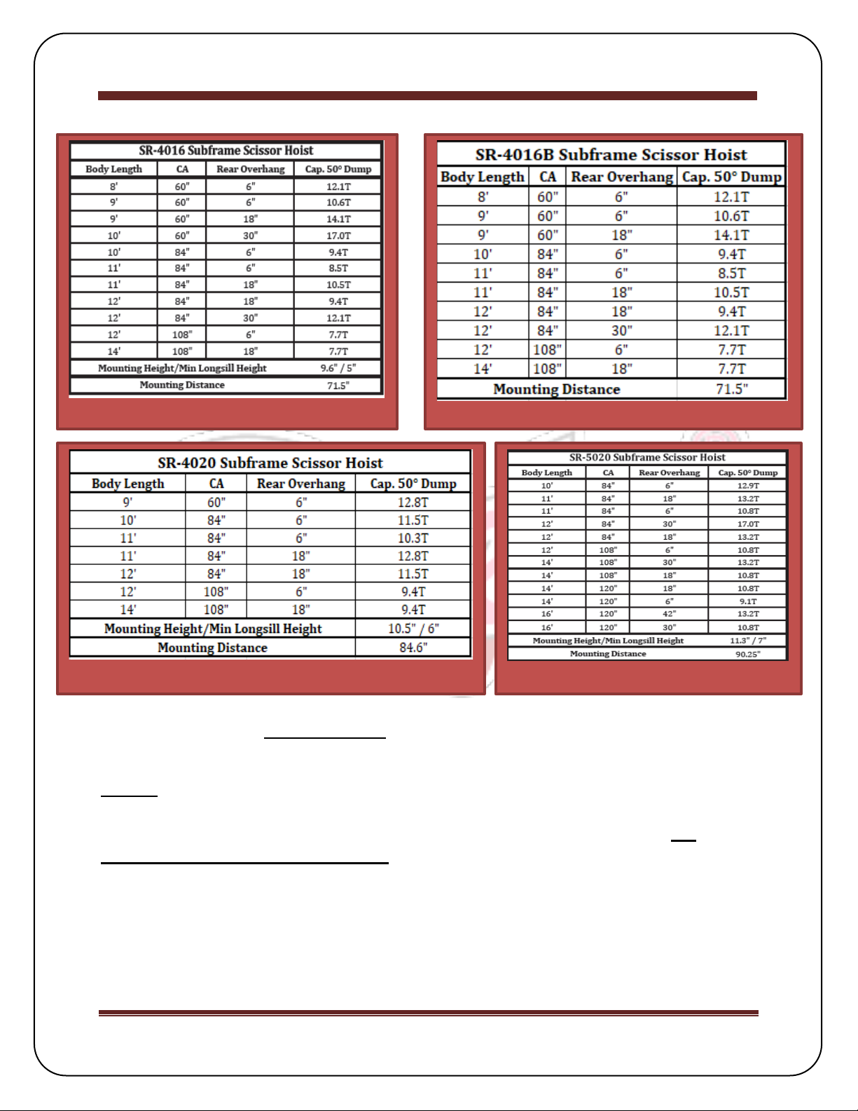
Capacity Chart.............................................................................................................3
Torque Values Chart....................................................................................................4
General Safety ...................................................................................... 4-5
Hydraulic System......................................................................................................4-5
Installation .......................................................................................... 6-15
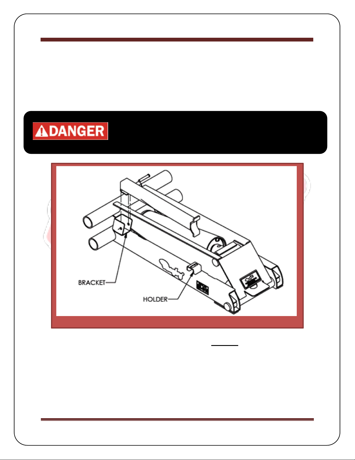
Body Prop Installation..................................................................................................6
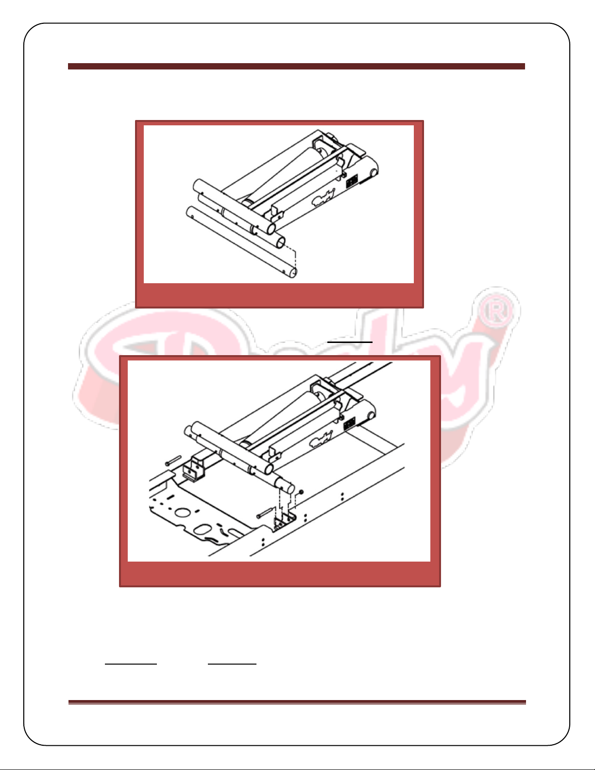
Hoist & Sub-frame Assembly....................................................................................7-8
Hoist & Subframe Installation..................................................................................8-13
45° Application Sub-frame Modification ....................................................................14
Decal Locations ......................................................................................................... 15
Operation................................................................................................16
Body Prop Operation.................................................................................................. 16
Maintenance...................................................................................... 16-17
Diagrams...............................................................................................................16-17

Rugby Manufacturing SR-Series Hoist Manual
1841488E Rugby Manufacturing Page 1
How to Use This Manual
This manual provides guidelines and instructions for correctly operating and
maintaining your Rugby Manufacturing product. Any and all people that own and
operate a Rugby Manufacturing dump trailer are recommended to read and fully
understand each section in this manual.
Labels
Throughout this manual, the three following types of labels will be used: Danger,
Warning, and Caution. For the safety of the operator, it is imperative that all labels are
obeyed.
Danger: Indicate[s] a hazardous
situation which, if not avoided, will
result in death or serious injury.
Warning: Indicate[s] a hazardous
situation which, if not avoided,
could result in death or serious
injury.
Caution: Indicate[s] a hazardous
situation which, if not avoided, could
result in minor or moderate injury.

Rugby Manufacturing SR-Series Hoist Manual
1841488E Rugby Manufacturing Page 2
Reference Information
Serial Number
This information is required for any warranty or service inquiries, and should be
recorded on the front page of this manual for easy reference.
The serial number is a decal located on the spacer plate of the hoist. (Figure 1).
Figure 1: Serial Number Locations
SR-4016
SR-4016B
SR-4020
SR-5020

Rugby Manufacturing SR-Series Hoist Manual
1841488E Rugby Manufacturing Page 3
Capacity Charts
The Capacity Charts (Figure 2, 3, 4, 5) are to be used as a reference when determining
capacity based on overhang.
NOTE: Approximately 10% additional capacity can be attained on an SR-4016 or SR-
4016B application if sub-frame and hoist are installed at 45°. A sub-frame modification
kit can be ordered from Rugby Mfg. if this installation is desired. Refer to the 45°
Application Sub-frame Modification section of this manual for additional information
and instructions.
Figure 2: SR-4016 Capacity Chart
Figure 3: SR-4016B Capacity Chart
Figure 5: SR-5020 Capacity Chart
Figure 4: SR-4020 Capacity Chart

Rugby Manufacturing SR-Series Hoist Manual
1841488E Rugby Manufacturing Page 4
Torque Value Chart
The Torque Values Chart (Figure 6) is to be used as a guide during installation.
General Safety
Hydraulic System
The hydraulic system supplied with an SR-series hoist manufactured
by Rugby Manufacturing Co. is made up of components (pump, valves,
reservoir, hoses, cylinder, etc.) that are designed to be compatible with
each other. Several different types of pump and hydraulic components are
available to power the SR-series hoists. Refer to the pump and hydraulic
component Installation and Operation Manual for more information.
If hydraulic components are substituted, it is the installer’s
responsibility to be sure they are compatible with the components supplied
by Rugby Manufacturing Co. Incompatible hydraulic components may
cause failure of the hoist which in turn could damage the truck, damage
other property, and cause human injury or death. Rugby Manufacturing
Company’s liability and warranty for a given hoist will be voided if it is
determined by Rugby Manufacturing Co. that substituted hydraulic
components were used that were incompatible with those supplied by
Rugby Manufacturing Co.
Figure 6: Torque Values

Rugby Manufacturing SR-Series Hoist Manual
1841488E Rugby Manufacturing Page 5
Bouncing or jerking of the hoist is to be avoided as it may
result in component failure, injury or death.
Unlatch tailgate prior to elevating a loaded dump body as
excessive forces on the rear of the dump body may result in
component failure.
Overloading of a truck can cause truck component damage,
injury or death. Never exceed the gross vehicle weight
(GVW) or gross axle weight (GAW) rating of your vehicle.
Do not operate the hoist until bystanders are free & clear of
the hoist and body.
Connecting the hoist to a hydraulic system with more
pressure (psi) or flow (gpm) than is recommended can lead
to damage, serious injury, or death.
Do not raise or drive a raised body against another object.
Doing so could result in equipment or property damage,
injury or death.
SR-SERIES HOISTS
4016/4016B/4020
5020
MAXIMUM HYDRAULIC FLOW
RATE (GPM)
4-6
6-9
MAXIMUM UP PRESSURE
(PSI)
3200
3200
MAXIMUM DOWN PRESSURE
(PSI)
1000
1000
Figure 7: Hydraulic Information Chart

Rugby Manufacturing SR-Series Hoist Manual
1841488E Rugby Manufacturing Page 6
Installation
Body Prop Installation
A body prop & required hardware is supplied with every SR-series hoist package. For
instructions on how to raise and lower the body prop, refer to the Operation section of
this manual.
1. Insert the body prop into the body prop bracket (Figure 8).
2. Fasten the body prop to the body prop bracket using the supplied hardware.
3. Lower the body prop to the down position & align with slot until the body prop
rests against the top of the holder.
The body prop is only to be used to prop an unloaded body.
Serious injury or death can occur if the body prop is
misused.
Figure 8: Body Prop Location

Rugby Manufacturing SR-Series Hoist Manual
1841488E Rugby Manufacturing Page 7
Hoist & Sub-frame Assembly
A full breakdown of the hoist & sub-frame components can be found in the Diagrams
section of this manual.
4. Slide the saddle shaft into the lower tube of the hoist so that approximately 4
inches extend past the tube on each side. (Figure 9.)
2. Position the hoist into the subframe by aligning each end of the saddle shaft into
the subframe brackets.
3. Secure the saddle shaft to the sub-frame with the provided hardware as shown in
Figure 10. Refer to Figure 6 for torque guidelines.
Figure 9: Saddle Tube Location
Figure 10: Sub-frame Positioning

Rugby Manufacturing SR-Series Hoist Manual
1841488E Rugby Manufacturing Page 8
Hoist & Sub-frame Assembly cont.
4. Position the provided 3/8” spacers under each sub-frame rail as far forward as
possible. Secure to rail by welding as shown. (Figure 11)
NOTE: Optional 12” or 24” bolt-on sub-frame extensions can be installed to convert the
9’ subframe to a 10’ or 11’ as required. For optional 45° dump angle applications, refer
to the 45° Application Sub-frame Modification section.
Hoist & Sub-frame Installation
Figure 11: Sub-frame Extension Kit
Figure 12: Hoist Position
Other manuals for SR-Series
1
This manual suits for next models
4
Table of contents
Popular Jack manuals by other brands

Pittsburgh
Pittsburgh 62590 Owner's manual & safety instructions

Powerbuilt
Powerbuilt 640405 Operating and maintenance instruction manual

Clarke
Clarke STRONG-ARM CTJ3000G quick start guide

Clarke
Clarke CTJ2500QLG Operating & maintenance instructions

Omega Lift Equipment
Omega Lift Equipment 18122C Operating instructions & parts manual

Pittsburgh
Pittsburgh 58816 Owner's manual & safety instructions


