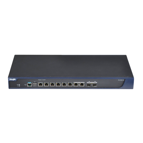
Ruijie RG-WS6512 Installation and operating manual

Ruijie RG-WS6512 Wireless Controller
Hardware Installation and Reference Guide
Document Version: V1.3
Date: August 16, 2023
Copyright © 2023 Ruijie
Networks

Copyright
Copyright © 2023 Ruijie Networks
All rights are reserved in this document and this statement.
Any reproduction, excerption, backup, modification, transmission, translation or
commercial use of this document or any portion of this document, in any form or by any
means, without the prior written consent of Ruijie Networks is prohibited.
Trademark and are owned by Ruijie
Networks.
All other trademarks or registered trademarks mentioned in this document are owned by
their respective owners.
Disclaimer
The products, services, or features you purchase are subject to commercial contracts and
terms. Some or all of the products, services or features described in this document may
not be within the scope of your purchase or use. Unless otherwise agreed in the contract,
Ruijie Networks does not make any express or implied statement or guarantee for the
content of this document.
Due to product version upgrades or other reasons, the content of this document will be
updated from time to time. Ruijie Networks reserves the right to modify the content of
the document without any notice or prompt.
This manual is for reference only. Ruijie Networks endeavors to ensure content accuracy
and will not shoulder any responsibility for losses and damages caused due to content
omissions, inaccuracies or errors.

I
Preface
Intended Audience
This document is intended for:
Network engineers
Technical support and servicing engineers
Network administrators
Technical Support
Ruijie Networks Website: https://www.ruijienetworks.com/
Technical Support Website: https://ruijienetworks.com/support
Case Portal: https://caseportal.ruijienetworks.com
Community: https://community.ruijienetworks.com
Technical Support Email: service_rj@ruijienetworks.com
Live Chat: https://www.ruijienetworks.com/rita
Conventions
1. Signs
The signs used in this document are described as follows:
Warning
An alert that calls attention to important rules and information that if not understood or
followed can result in data loss or equipment damage.
Caution
An alert that calls attention to essential information that if not understood or followed
can result in function failure or performance degradation.
Note
An alert that contains additional or supplementary information that if not understood or
followed will not lead to serious consequences.

II
Specification
An alert that contains a description of product or version support.
2. Note
The manual offers configuration information (including model, port type and command
line interface) for indicative purpose only. In case of any discrepancy or inconsistency
between the manual and the actual version, the actual version prevails.

Hardware Installation and Reference Guide Product Introduction
1
1 Product Introduction
1.1 Overview
The RG-WS6512 is an access controller (AC) released by Ruijie Networks. It is mainly used
in medium- and large-sized wireless local area networks (WLANs) to provide powerful
access control functions.
1.2 Product Appearance
Figure 1-1 Appearance of the RG-WS6512
Figure 1-2 Front Panel of the RG-WS6512
Figure 1-3 Rear Panel of the RG-WS6512

Hardware Installation and Reference Guide Product Introduction
2
Description
1. System logo LED
2. Reset button
3. RJ45 console port
4. USB 2.0 port
5. 10/100/1000Base-T auto-
sensing Ethernet ports
6. 1000Base-X SFP combo ports
7. 10GBASE-SR/LR SFP+ ports
8. QR code for Ruijie AP and AC
initialization guide
9. Power modules
10. Grounding screw
Note
The nameplate is at the bottom of the access controller.
1.3 Product LED Indicators
LED
Status
System logo LED
Initializing upon power-on/Upgrading: blinking green
Proper running upon initialization completion: steady
green
Abnormal running: steady red
LEDs for 1000 Mbps
copper ports (1 to 8)
1000 Mbps link: steady green
100/10 Mbps link: steady yellow
Data receiving/transmitting: blinking
LEDs for 1000 Mbps
optical ports (1F to 8F)
Link: steady green
Data receiving/transmitting: blinking green
LEDs for 10 Gbps optical
ports (1F to 4F)
Link: steady green
Data receiving/transmitting: blinking green
Pressing the Button to Reboot the System
Press the Reset button. The system is rebooted.

Hardware Installation and Reference Guide Product Introduction
3
Press and hold the Reset button for 3s. The system is rebooted with restored default
settings.
1.4 Technical Specifications
1.4.1 Dimensions and Weight
Dimensions and
Weight
RG-WS6512
Dimensions (W × D
× H)
440 mm ×340 mm ×43.6 mm (17.32 in. ×13.39 in. ×1.72in.)
(excluding the foot pads)
Rack height
1 U
Weight
Net weight: 5.9 kg (13.01 lbs., one power module for factory
delivery)
1.4.2 Port Specifications
Item
RG-WS6512
Fixed service port
One 10/100/1000Base-T MGMT port with auto-negotiation
Eight combo ports (when the combo port is used as an
electrical port, it supports 10/100/1000Base-T auto-
negotiation)
Four 10GE SFP + ports
Fixed management
port
One RJ45 console port
Two USB ports
Status LED
One system LED
20 service port status LEDs
Button
One reset button

Hardware Installation and Reference Guide Product Introduction
4
1.4.3 Power Supply and Consumption
Item
RG-WS6512
Max. power
consumption
70 W
Power pedundancy
Two power modules (one power module for factory delivery)
Input voltage
100V AC~240V AC,50Hz~60Hz
Output voltage
12V/5.83A
Note
A combo port consists of an optical port and an electrical port. The optical port and
electrical port cannot work at the same time. If one port is enabled, the other is disabled.
You can select the port type as required.
1.4.4 Environment and Reliability
Item
RG-WS6512
Temperature
Operating temperature: 0°C to 45°C (32°F to 113°F)
Storage temperature: –40°C to +70°C (–40°F to +158°F)
At a height between 3000 m (9842.52 ft.) to 5000 m (16404.20 ft.)
above the sea level, every time the altitude increases by 200 m
(722 ft.), the maximum temperature decreases by 1°C (1.8°F).
Humidity
Operating humidity: 10% to 90% RH (non-condensing)
Storage humidity: 5% to 95% RH (non-condensing)
Regulatory
Compliance
IEC 62368-1, EN 62368-1, EN 55032, EN 55035, EN 61000-3-3, EN
IEC 61000-3-2, and ETSI EN 300 386
MTBF
≥200,000 hours

Hardware Installation and Reference Guide Product Introduction
5
Note
Due to the variety of USB flash drives, not all of them are supported. A USB flash drive with the FAT32
file system format is recommended.
Caution
Please avoid vibration and shock when moving and using the device.
Before using hard disks provided by customers, format them to the EXT3 format.
This is a Class A product. In a domestic environment, this product may cause radio interference. In this
case, users are advised to take proper measures against the interference.

Hardware Installation and Reference Guide Preparing for Installation
6
1.5 RG-PA701 Power Supply Model
1.5.1 Power Supply
Parameter
Description
Rated voltage
range
100 V AC to 240 V AC
Frequency
50 Hz to 60 Hz
Rated current
2 A Max.
Power cord
10 A power cord
Current
equalization
Supported
The RG-WS6512 adopts AC input and supports power module redundancy.
1.5.2 Power LED
LED
Status
DC OK
Normal input: steady green
Abnormal input: off
2 Preparing for Installation
2.1 Precautions
An AC functions as a transfer station for network connections. Its functionality is related
to the normal operation of the entire network. When installing and using the RG-
WS6512, pay attention to the following safety recommendations:
Do not place the device in a wet position, and keep the device away from liquid.

Hardware Installation and Reference Guide Preparing for Installation
7
Install the device in a position far away from heat sources.
Ensure that the device is properly grounded.
Wear an anti-static wrist strap during installation and maintenance.
Do not wear loose clothing, which may be hooked by the device, thereby causing
damage to the device. Fasten your belt and scarf, and tie your sleeves.
Keep tools and components away from walking areas to prevent collisions.
An uninterrupted power supply (UPS) is recommended to prevent power outage and
interference.
If the clock read from the device is inaccurate, check whether the clock of the device
has been set. If the clock has not been set, the clock read from the device may be
inaccurate. If the clock of the device has been set accurately, the button battery inside
the device may be exhausted. A button battery can be generally used for about 10
years. After the battery is exhausted, the clock will be inaccurate.
To ensure normal running of the device, see storage temperature and humidity
specifications.
Caution
An improper type of battery can cause damage and danger to the device. To replace
the battery, contact Ruijie technical support.
This is a Class A product. In a domestic environment, this product may cause radio
interference. In this case, users are advised to take proper measures against the
interference.
If the device has been powered off for over 18 months, power on the device and
keep it run for over 24 hours consistently.
Note
Install the device in a location with restricted access.
The device is a professional device and requires professionals or related technical
personnel to install it.

Hardware Installation and Reference Guide Preparing for Installation
8
2.2 Installation Environment Requirements
The RG-WS6512 must be installed indoors. To ensure its normal operation and prolonged
service life, the installation site should meet the following requirements.
2.2.1 Temperature/Humidity Requirements
To ensure the normal operation and prolonged service life of the device, maintain an
appropriate temperature and humidity in the equipment room. If the humidity in the
equipment room keeps high for a long time, some mechanical performance issues may
occur, such as the poor insulation of insulating materials and even electric leakage. If the
relative humidity is too low, the insulating gasket may shrink and cause the fixed screws
to loosen. Moreover, it is easy to generate static electricity and harm the circuits in the
device. Too high temperatures can accelerate the aging of insulation materials, greatly
reducing the reliability of the device and severely affecting its service life. The following
table provides the temperature and humidity requirements. (The related specifications in
Chapter 1 prevail.)
Temperature
Relative Humidity
Long-Term
Operating
Short-Term
Operating
Long-Term
Operating
Short-Term
Operating
15°C to 30°C (59°F
to 86°F)
0°C to 45°C (32°F
to 113°F)
40% to 65%
10% to 90%
Note
The ambient temperature and humidity of the device are measured at the point
that is 1.5 m (59.06 in.) above the floor and 0.4 m (15.75 in.) before the device when
there is no protective plate in front or at the back of the device.
Short-term operating indicates that the device functions for no more than
consecutive 48 hours or accumulated 15 days per year.
The temperature and humidity ranges in extremely severe environments generally refer to the possible
values in an equipment room where the air-conditioning system fails and is recovered in no more than 5
hours each time.

Hardware Installation and Reference Guide Preparing for Installation
9
2.2.2 Cleanliness Requirements
Dust poses a major threat to the device. Indoor dust causes electrostatic adherence
when falling on the device, resulting in poor contact. Such electrostatic adherence may
occur more easily when the relative humidity is low, not only affecting the service life of
the device, but also causing communication faults.
Max. Diameter
(μm)
0.5
1
3
5
Max.
Concentration
(Particle
Quantity/m3)
1.4×10⁷
7×10⁵
2.4×10⁵
1.3×10⁵
Apart from dust, the sulfide in the air in the equipment room must also meet strict
requirements. These harmful substances will accelerate metal corrosion and the aging of
some components. Therefore, the equipment room should be properly protected against
the intrusion of harmful gases, such as sulfur dioxide, hydrogen sulfide, nitrogen
dioxide, ammonia gas, and chlorine gas. The following table lists limit values for harmful
gases.
Gas
Average (mg/m3)
Maximum (mg/m3)
Sulfur dioxide
(SO2)
0.2
1.5
Hydrogen sulfide
(H2S)
0.006
0.03
Nitrogen dioxide
(NO2)
0.04
0.15
Ammonia gas
(NH3)
0.05
0.15
Chlorine gas (CI2)
0.01
0.3

Hardware Installation and Reference Guide Preparing for Installation
10
2.2.3 Anti-static Requirements
Although the anti-static treatment has been applied to the RG-WS6512 during the circuit
design, strong static electricity will still cause damage to the circuit board. Regarding the
communication network connected with the device, static electricity mainly comes from
the following two aspects:
Outdoor high-voltage power cables, lightning, and other external electric fields
Indoor floor materials and the internal structure of the device
To prevent damage from static electricity, pay attention to the following:
Properly ground the device and floor.
Keep the indoor installation environment clean and free of dust.
Maintain the appropriate temperature and humidity.
Wear the anti-static wrist strap and anti-static clothing when touching the circuit board
of the device.
Place the disassembled circuit board facing up on an anti-static workbench or put it in
an electromagnetic shielding bag.
When observing or transferring the disassembled circuit board of the RG-WS6512,
hold the outer edges of the circuit board with your hands to avoid directly touching
the components on the circuit board.
2.2.4 Anti-interference Requirements
Anti-interference herein refers to resistance against electromagnetic and current
interference. The anti-interference requirements are as follows:
Take interference prevention measures for the power supply system.
Keep the device far away from the lightning protection and grounding system of the
power device.
Keep the device far away from high-frequency high-current devices such as high-
power radio transmitting station and radar launcher.
Take electromagnetic shielding measures when necessary.
2.2.5 Other Requirements
Regardless of whether the device is installed in a cabinet or placed on a workbench, the
following conditions must be met:

Hardware Installation and Reference Guide Preparing for Installation
11
Maintain sufficient clearance around the air vents for heat dissipation. It is
recommended to install the device in a 19-inch standard cabinet. Otherwise, place the
device horizontally on a clean panel. It is recommended to install air conditioners in
hot areas.
The ventilation and heat dissipation of the cabinet and workbench are satisfactory.
The cabinet or the workbench is strong enough to support the weight of the device
and its accessories.
The cabinet or the workbench are properly grounded.
2.3 Tools and Relevant Devices
Before installing the device, prepare the following tools and relevant devices:
Tools
Phillips screwdriver and anti-static wrist strap
Cables
Power cord, RJ45 serial cable, Ethernet cable, and ground cable
Relevant
Devices
Hub or switch, configuration terminal (such as a PC with
HyperTerminal), and power socket

Hardware Installation and Reference Guide Installing the AC
- 12 -
3 Installing the AC
3.1 Installation Procedure
To avoid device damage caused by any improper operation during the installation
process, install the device according to the procedure shown in the following figure.
3.2 Securing the AC
Install the device in the specified location. After completing the installation preparations,
secure the device to the specified location. The device is generally installed in the
following locations:
Installing the Device in a Cabinet
The device is designed according to the dimensions of a standard cabinet, and can be
installed and secured with the delivered accessories based on the cabinet condition.
Start
Preparation: Read Chapter 2
and confirm that all the
related requirements are
met.
Install the device in the
specified location.
Connect cables.
Verify the installation.
Power on the device.
Configure the device.
End

Hardware Installation and Reference Guide Installing the AC
- 13 -
Installing the Device on a Workbench
In most cases, a 19-inch standard cabinet is unavailable. Therefore, a simple way is to
place the device on a clean workbench. During the process, pay attention to the
following:
Ensure that the workbench is stable and properly grounded.
Attach the plastic pads delivered with the device to the corresponding marks on the
bottom of the device, while leaving a clearance of 10 cm (3.94 in.) around the device
for heat dissipation.
Do not place heavy objects on the device.
3.3 Installing the Power Cord
The RG-WS6512 supports AC power supply (100 V to 240 V/50 Hz to 60 Hz) The selected
power supply modules must meet the system power requirements.
Note
For details about the power supply types supported by the device, see Chapter 1.
The power cord of the RG-WS6512 has three cores. You are advised to use a single-phase
three-core power socket or a multi-function power socket with a neutral point connector.
The neutral point of the power supply must be well grounded in the building. In general,
the power supply neutral point of the building has been buried in the ground during the
cabling. Users need to confirm whether the power supply of the building has been
properly grounded.
Connect the power cord by performing the following steps:
Plug one end of the power cord into the power socket on the rear panel of the device
and the other end of the power cord into the AC power socket.
Check the status of power LED on the front panel of the device. If the LED is on, the
power cord is connected correctly.
3.4 EMC Grounding
Grounding required for electromagnetic compatibility includes shielded grounding, filter
grounding, noise and interference suppression, and level reference, which contribute to
the overall grounding requirements. The grounding resistance should be smaller than 1
ohm. The rear panel has a grounding stud, as shown in Figure 3-1.

Hardware Installation and Reference Guide Installing the AC
- 14 -
Figure 3-1 Grounding
3.5 Connecting to the Console
The RG-WS6512 has an EIA/TIA-232 asynchronous serial console port, which allows users
to complete the local configuration of the RG-WS6512. The following table provides the
details about the console port. If the RG-WS6512 is configured by using the web, there is
no need to connect to the console.
Parameter
Description
Connector
RJ-45
Interface
Standard
Asynchronous EIA/TIA-232
Baud Rate
9600 bps (default), 57600 bps, and 115200 bps
Supported
Services
1. CLI
2. Connection to character terminals
3. Asynchronous interface for terminal access
Users can connect to the console port of the RG-WS6512 based on the following
procedure:
Connect one end of the RJ45 serial cable delivered with the RG-WS6512 to the console
port, and the other end to the DB-9 male connector of the microcomputer that is used to
configure the AC.

Hardware Installation and Reference Guide Installing the AC
- 15 -
3.6 Verifying the Installation
After the mechanical installation of the RG-WS6512 is completed, check the following
items before powering on the RG-WS6512:
If the device is installed inside a cabinet, verify that the cabinet and mounting ears are
secured. If the device is placed on a workbench, verify that sufficient space for heat
dissipation is reserved around the device and the workbench is steady.
Verify that the power supply connected to the power cord meets the requirements of
the device.
Verify that the ground cable of the device is correctly connected.
Verify that the device is correctly connected to other devices, such as the configuration
terminal.

Hardware Installation and Reference Guide Verifying Operating Status
16
4 Verifying Operating Status
4.1 Setting Up the Configuration Environment
When the AC is used for the first time, it must be configured by using the console port.
The specific steps are as follows:
Step 1: Connect the serial port of a character terminal or microcomputer to the
console port (also called configuration port or control panel port) of the RG-WS6512 by
using a standard RS232 cable.
Step 2: Configure the communication parameters of the terminal. If a microcomputer
is used, a terminal emulation program, such as the HyperTerminal provided by the
Windows operating system, must be running. HyperTerminal is used as an example to
describe the procedure:
1. Run the HyperTerminal software to create a connection.
2. Select the serial port to connect with the console port of the RG-WS6512.
3. Configure the communication parameters. By default, the baud rate is set to 9600, data
bit to 8, no parity check, stop bit to 1, and no flow control.
4. Choose File > Properties > Settings and set Terminal Emulation to VT100.
Figure 4-1 Creating a Connection
Figure 4-2 Selecting the Serial Port
Table of contents
Other Ruijie Controllers manuals

Ruijie
Ruijie RG-WS6024 Series Installation and operating manual
Ruijie
Ruijie RG-WS6108 Series Installation and operating manual
Ruijie
Ruijie RG-WS5708 Series Installation and operating manual

Ruijie
Ruijie RG-WS6816 Series Installation and operating manual

Ruijie
Ruijie RG-WS6108 Series Installation and operating manual
Popular Controllers manuals by other brands

Trane Technologies
Trane Technologies Symbio 800 Integration guide

Tamarack Technologies
Tamarack Technologies Airetrak 1A ADVANTAGE Product guide

HIMA
HIMA HIMatrix GEH 01 manual

KE2
KE2 Evaporator Efficiency Condensed Quick Start Guide

Kidde
Kidde FENWAL 35-71 Series manual

ABB
ABB Jocab Safety Vital 2 Operating instruction