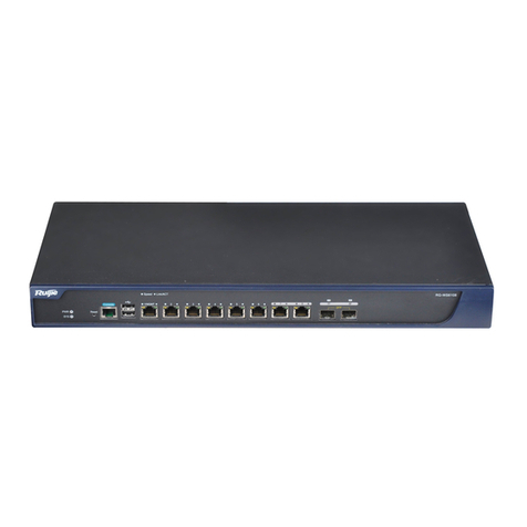
Ruijie RG-WS6816 Series Installation and operating manual

Ruijie RG-WS6816 Series Wireless Controllers
Hardware Installation and Reference Guide V1.02

·
Copyright statement
Ruijie Networks©2019
Ruijie Networks reserves all copyrights of this document. Any reproduction, excerption, backup,
modification, transmission, translation or commercial use of this document or any portion of this document,
in any form or by any means, without the prior written consent of Ruijie Networks is prohibited.
Exemption statement
This document is provided “as is”. The contents of this document are subject to change without any notice.
Please obtain the latest information through the Ruijie Networks website. Ruijie Networks endeavors to
ensure content accuracy and will not shoulder any responsibility for losses and damages caused due to
content omissions, inaccuracies or errors.

Preface
Thank you for using our products. This manual will guide you through the installation of the device.
Scope
It is intended for the users who have some experience in installing and maintaining network hardware. At the same time, it
is assumed that the users are already familiar with the related terms and concepts.
Obtaining Technical Assistance
Ruijie Networks Website: https://www.ruijienetworks.com/
Technical Support Website: https://ruijienetworks.com/support
Case Portal: https://caseportal.ruijienetworks.com
Community: https://community.ruijienetworks.com
Technical Support Email: [email protected]
Skype: [email protected]
Related Documents
Documents
Description
Configuration Guide
Describes network protocols and related mechanisms that supported by the
product, with configuration examples.
Command Reference
Describes the related configuration commands, including command modes,
parameter descriptions, usage guides, and related examples.
Documentation Conventions
The symbols used in this document are described as below:
This symbol brings your attention to some helpful suggestions and references.
This symbol means that you must be extremely careful not to do some things that may damage the device or cause
data loss.

Hardware Installation and Reference Guide Product Overview
1Product Overview
The RG-WS6816 wireless LAN controller is introduced by Ruijie Networks to provide powerful WLAN access control for
medium-large-sized wireless networks.
1.1 RG-WS6816
Table 1-1 Technical Specifications of RG-WS6816
Model
RG-WS6816
DDR3 SDRAM:16GB
BOOTROM: 8MB
Memory
FLASH: 512MB
8-1000M combo Ethernet ports.
The copper port supports 10/100/1000Mbps auto-negotiation and network cable/cross-over
cable auto-identification.
The fiber port supports the 1000BASE-SX/LX/ZX mini GBIC optical transceiver.
4-10Gigabit fiber ports are provided, including port 2 combo with 1000M ports 0/1, 0/2, 0/3, 0/4
and port 3 combo with 1000M ports 0/5, 0/6, 0/7, 0/8.
Modules XG-SFP-SR-MM850, XG-SFP-LR-SM1310 and XG-SFP-ER-SM1550 are supported.
One management port, which supports 10/100/1000Mbps auto-negotiation and network
cable/cross-over cable auto-identification.
One console port.
Port
Two USB ports.
Power Supply
Module
Up to two RG-PA300I power modules are supported. One is supplied.
Hot Swapping
Fan tray hot swapping: supported
Power hot swapping: supported
Ethernet port: 10Base-T/100Base-TX/1000Base-TX and 1000BASE-SX/LX/ZX
Interface Standard
Configuration port (Console port): RS-232
Dimensions
(W x D x H)
560mm x 440mm x 88.1mm (excluding foot pad)
Voltage
100-240V~, 50/60Hz
Power Consumption
100W max.
Operating
Temperature
0ºC to 45ºC (32 to 113ºF)
Operating Humidity
5% to 95% RH (noncondensing)
The system may not support all USB disks. It is recommended to use the Kingston USB disk and set the file system
format to FAT32.
RG-WS6816 wireless controller is a class A product. In a domestic environment, this product may cause radio
interference, in which case the user may be required to take adequate measures.

Hardware Installation and Reference Guide Product Overview
Product Image
Figure 1-1 Front Panel of RG-WS6816
Figure 1-2 Rear Panel of RG-WS6816
LED Indicators
LED
State
Meaning
Off
The power module is NOT in the position.
Solid green
The power module is operational.
PWR1 and PWR2
Solid red
The power module fails or NOT receiving power.
Blinking green
The system is being initialized.
Solid green
The initialization process is complete.
SYS
Solid red
The system sends out an alarm.
Off
The fan module is NOT in the position.
Solid green
The fan module is operational.
FAN
Solid red/ Blinking green
The fan module fails.
Link
Solid green
The management port is connected.
ACT
Blinking green
The management port is receiving or transmitting data,
Solid green
The copper port is connected at 1000 Mbps.
Solid green
The copper port is connected at 10/100 Mbps.
1-8 Gigabit copper
ports
Blinking green
The copper port is receiving or transmitting data.
Solid green
The fiber port is connected.
1F-8F Gigabit
fiber ports
Blinking green
The fiber port is receiving or transmitting data.

Hardware Installation and Reference Guide Product Overview
1.2 Module
1.2.1 RG-PA300I
Module Appearance
Figure 1-3 Appearance of RG-PA300I Power Module
Indicator
LED
State
Meaning
Off
The power input fails.
IN
Solid green
The power input is operational.
Off
The power output fails.
OUT
Solid green
The power output is operational.
Off
The power module fails.
FAIL
Solid red
The power module is operational.
Specifications
Model
RG-PA300I
Rated Input
Voltage and
Current
100-240V~, 50-60Hz, 6.5A
Rated Output
Voltage and
Current
12V: 1-25 A
12VFAN: 0-5 A
Rate Output
Power.
300W
Hot Swapping
Supported
N+1 Backup
Supported
Power Factor
Correction
Supported
Protection
Input overvoltage protection, input undervoltage protection, output overvoltage protection, output
overcurrent protection, short circuit protection, over-temperature protection
Communication
Communication with the host is supported. You can check the power temperature, output power
and other information through the host. The valid power temperature is in the range from -5ºC to
+50ºC (±2ºC).Otherwise, errors may occur to temperature display.

Hardware Installation and Reference Guide Product Overview
1.2.2 WNM-4GE-S
Module Appearance
Figure 1-4 Appearance of WNM-4GE-S
The WNM-4GE-S module applies to only RG-WS6816.
Indicator
LED
State
Meaning
Solid green
The system is being initialized.
Blinking green
The initialization process is complete.
RDY
Solid red
The system sends out an alarm.
Solid green
The port is connected at 1000 Mbps.
Solid yellow
The port is connected at 10/100 Mbps.
1-4 Gigabit copper
ports
Blinking
The port is receiving or transmitting data.
Solid green
The port is connected.
1F-4F Gigabit
fiber ports
Blinking green
The port is receiving or transmitting data.
Specifications
Model
WNM-4GE-S
Memory
EEPROM: 2Kb
4-1000M combo Ethernet ports are provided.
The copper port supports 10/100/1000Mbps auto-negotiation and network cable/cross-over
cable auto-identification.
I/O Configuration
The fiber port supports the 1000BASE-SX/LX/ZX mini GBIC optical transceiver.
Hot Swapping
Not supported
Interface Standard
Ethernet port:
10Base-T/100Base-TX/1000Base-TX and 1000BASE-SX/LX/ZX copper port
1000BASE-SX/LX/ZX fiber port.
Dimensions
(W x D x H)
176 mm x 213 mm x 32 mm
Voltage
12V
Power Consumption
15 W max
Operating
0 to 45ºC (32 to 113℉)

Hardware Installation and Reference Guide Product Overview
Temperature
Operating Humidity
10% to 90% RH (noncondensing)
1.2.3 WNM-2XS-S
Figure 1-5 Appearance of WNM-2XS-S
The WNM-2XS-S module applies to only RG-WS6816.
Indicator
LED
State
Meaning
Solid green
The system is being initialized.
Blinking green
The initialization process is complete.
RDY
Solid red
The system sends out an alarm.
Solid green
The port is connected.
0F-1F 10 Gigabit
fiber ports
Blinking green
The port is receiving or transmitting data.
Specifications
Model
WNM-2XS-S
Memory
EEPROM: 2Kb
I/O Configuration
The 10 gigabit fiber port supports the 10G-BASE-SR/LR/ER/ZR optical transceiver.
Hot Swapping
Not supported
Interface Standard
10G-BASE-SR/LR/ER/ZR fiber port.
Dimensions
(W x D x H)
176 mm x 213 mm x 32 mm
Voltage
12V
Power Consumption
15 W max
Operating
Temperature
0ºC to 45ºC (32 to 113℉)
Operating Humidity
10-90% RH (noncondensing)

Hardware Installation and Reference Guide Preparation for Installation
2Preparation for Installation
2.1 Precautions
The wireless controller acts as a network repeater and its working affects the normal operation of the whole network.
The following suggestions are advised for the installation and use of RG-WS6816:
Do not place the wireless controller in a damp/wet location. Do not let any liquid enter the chassis.
Keep the wireless controller far away from the heat source.
Ensure that the wireless controller is properly grounded.
Wear an anti-static wrist strap during installation and maintenance.
Do not wear loose clothes to avoid hooking any parts. Before operation, tighten your band, shawl, and sleeves.
Put the tools and parts away from where people walk by.
Use UPS to prevent power failure and other interferences.
If the clock is not accurate, check whether the clock has been configured. If not, the inaccuracy is likely to occur. If
the clock has been configured, the inaccuracy may be caused by the battery running out of power. In general, the
button battery lasts about 10 years.
Misuse of battery may cause damage to the device or hurt to people. Do not replace battery by yourself. Instead,
contact Ruijie Service Center for the replacement of battery.
This device is an A-class product. It may cause radio interference in living environment, which may require you to
take anti-interference measures.
Keep the device within the restricted-access area.
The device should be installed by professionals or technicians.
2.2 Preparing Installation Site
RG-WS6816 is for indoor use only. To ensure its normal operation and prolong its life span, the installation site should
meet the following requirement:
2.2.1 Temperature and Humidity Requirements
To ensure normal operation and service life of the device, maintain appropriate temperature and humidity levels in your
equipment room. See Table 2-1. Improper room temperature and humidity can cause damages to the device. High
relative humidity may affect insulation materials, resulting in poor insulation and even electrical leakage, and sometimes
may lead to change of mechanical properties of materials and corrosion of metal parts. Low relative humidity may dry and
shrink insulation sheets and cause static electricity that can damage the circuitry inside the device. High temperature
greatly reduces reliability of the device and shortens its service life.
Table 2-1 Required Temperature and Humidity for the RG-WS6816

Hardware Installation and Reference Guide Preparation for Installation
Relative Temperature
Long-time working condition
short-time working condition
Long-time working condition
short-time working condition
15ºC to 30ºC (59ºF to 86ºF)
0ºC to 45ºC (32ºF to 113ºF)
40%~65%
5%~95%
The ambient temperature and humidity are measured at a point 1.5 meters (4.9 feet) above the ground and 0.4
meters (1.3 feet) before the device when there is no protective board in the front or back of the rack.
The short-term working condition refers to a period no longer than consecutive 48 hours or accumulated 15 days a
year.
The extreme working condition refers to the temperature and humidity of the machine room where the air conditioner
fails for no more than five hours.
2.2.2 Cleanness Requirements
Dust poses a serious threat to device operation. Dust that falls onto the surface of the device can be absorbed onto metal
contact points by static electricity, resulting in poor contact. Electrostatic absorption of dust occurs more easily when the
relative humidity is low, which may shorten the service life of the device and cause communication failures. Table 2-2
shows the maximum concentration and diameter of dust allowed in the equipment room.
Table 2-2
Maximum diameter (µm)
0.5
1
3
5
Maximum content (number of
particles in one cubic meter)
1.4×10⁷
7×10⁵
2.4×10⁵
1.3×10⁵
Besides, the contents of salts, acids and sulfides in the air are also strictly limited for the equipment room. These
substances can accelerate metal corrosion and the aging of some parts. Table 2-3 describes the limit of some hazardous
gases such as SO2, H2S, NO2and Cl2 in the equipment room.
Table 2-3
Gas
Average (mg/m3)
Maximum (mg/m3)
SO2
0.2
1.5
H2S
0.006
0.03
NO2
0.04
0.15
NH3
0.05
0.15
Cl2
0.01
0.3
2.2.3 Static Discharge Damage Prevention
Although much has been done in RG-WS6816 to prevent static electricity, great damage may be caused to the circuitry
when the static electricity exceeds a certain limit. Electrostatic induction may come from the following sources:
External electric field produced by the high-voltage supply cable, lightning, etc;
Internal systems such as the indoor floor and the entire structure.
To prevent damage from static electricity, you must pay attention to the following:
Properly ground the equipment.
Take dust prevention measures in the room.
Maintain an appropriate humidity and temperature.

Hardware Installation and Reference Guide Preparation for Installation
Always wear an anti-static wrist strap when you touch any circuit board.
Place the circuit board on an anti-static workbench or in an anti-static shielding bag.
Try to hold a circuit board by its edges. Do not touch any components or the PCB.
2.2.4 Anti-Interference Requirements
The wireless controller is susceptible to external interference such as electromagnetic wave and current. Note that:
Provide the power system with effective anti-interference measures.
It is recommended that the wireless controller be installed far away from the grounding device.
Keep the wireless controller away from high-power radio stations, radar stations, and high-frequency high-current
devices.
Use EMI shielding when necessary.
2.2.5 Installation Site Requirements
To install the wireless controller whether in the cabinet or on the workbench, pay attention to the following items:
Ensure that enough space is reserved around the air inlet and exhaust vents for ventilation and heat dissipation. It is
recommended that the wireless controller be installed in a standard 19-inch cabinet. Otherwise, use a clean platform
as a workbench. It is recommended to equip the installation site with an air conditioner if it is hot.
Ensure that the cabinet or the workbench is provided with proper ventilation and heat dissipation system.
Ensure that the cabinet or the workbench is sound enough to bear the weight of the wireless controller and its
accessories.
Ensure that the cabinet or the workbench is properly grounded.
2.3 Installation Tools
Installation Tool
Cross screwdriver and anti-static wrist strap
Cable
Power cord, configuration cable, Ethernet cable and grounding cable
Device
Hub/switch, configuration terminal (such as PC with Hyperterm) and power socket

Hardware Installation and Reference Guide Installing Wireless Controller
3Installing Wireless Controller
3.1 Installation Flowchart
Please follow the following procedure to install the wireless controller to ensure the smooth installation and avoid any
damage to the device.
Begin
Read Chapter 2
Ensure Requirements are Met
Mount Wireless Controller
Connect Cables
Verify Installation
Power on Wireless Controller
Configure Wireless Controller
Complete
3.2 Mounting Wireless Controller
Now the wireless controller is ready for installation. Mount it to either of these two places.
A cabinet
A workbench
3.2.1 Mounting RG-WS6816 in Cabinet
RG-WS6816 is designed according to the specification of 19-inch standard cabinet. Use the supplied mounting accessory
for installation.

Hardware Installation and Reference Guide Installing Wireless Controller
3.2.2 Mounting RG-WS6816 on Workbench
In the absence of a 19-inch standard cabinet, install the wireless controller on a clean workbench. During the operation,
pay attention to the following items:
The workbench is firm and well-grounded.
The supplied plastic cushion is stuck to the small hole at the bottom of the wireless controller and a 10 cm clearance
is reserved for dissipation.
No weight is placed on the top of the wireless controller.
3.3 Installing Power Cable
RG-WS6816 supports AC (100 VAC to 240 VAC; 50/60 Hz). Make sure that your power supply meets the requirement.
See Chapter 1 for details about the power module.
RG-WS6816 uses three-wire power cable. It is recommended to use single-phase three-wire power socket or
multi-functional microcomputer socket with neutral-point connector. The neutral-point needs to be grounded safely. Check
whether the power supply in your building is grounded properly.
Follow the following steps to install the power cable:
1) Connect one end of the supplied power cable to the socket on the rear panel of the device and another to the AC
power socket.
2) Check the power indicator on the front panel is on. If it is, it means that the power cable is correctly connected.
3.4 EMS & Secure Grounding
The ground required for EMC design includes shielding ground, filter ground, noise and interference suppression, and
level reference. All the above constitute the comprehensive grounding requirements. The grounding resistance should be
smaller than 1Ω. The RG-WS6816 wireless controller has a grounding pole on the rear panel, as shown in Figure 3-1.
Figure 3-1 RG-WS6816 Grounding

Hardware Installation and Reference Guide Installing Wireless Controller
3.5 Connecting Console
RG-WS6816 supplies an EIA/TIA-232 configuration console for local configuration. If you configure RG-WS6816 through
Web, skip this part.
Table 3-1 Console Attributes
Parameter
Description
Connector
RJ-45
Interface Standard
Asynchronous EIA/TIA-232
Baud Rate
57,600 bps, 115,200 bps, 9,600 bps (default)
Supported Services
Command line interface
Connection to character terminals
Providing terminal access service as an asynchronous interface
Connect one end of the supplied configuration cable to the console port of the wireless controller, and the other end to the
DB-9 male serial adapter of the microcomputer.
3.6 Verification
When you have installed the wireless controller, before powering on it, pay attention to the following items:
If the wireless controller is stalled in a cabinet, check the mounting brackets of the cabinet and wireless controller are
firm. If the wireless controller is installed on the workbench, check there is enough room around the wireless
controller for heat dissipation and the workbench is firm.
Check the power supply meets the requirements.
Check the grounding cable is correctly connected.
Check the wireless controller is connected correctly to other devices such as the configuration terminal

Hardware Installation and Reference Guide Configuration Guide
4Configuration Guide
4.1 Setting up Configuration Environment
When you use the wireless controller for the very first time, you will need to configure it through a console port as follows:
As shown in the following figure, connect the serial port of a character terminal or microcomputer to the console port
through an RS232 cable.
Set the communication parameters of the terminal. For a microcomputer, you will need to run a terminal emulation
program like Windows operating system’s Hyperterm. Take Hyperterm for example.
1. Run Hyperterm and create a connection.
2. Select the serial port to be connected with the console port of the wireless controller, as shown in figure 4-2.
3. Set communication parameters as follows: baud rate to 9600, data bit to 8, stop bit to 1, parity to No, flow control to
No, as shown in figure 4-3.
4. Go to File->Property->Settings and set terminal emulation type to VT100.
Figure 4-1 Creating Connection
Figure 4-2 Selecting Serial Port to be Connected with Console Port.

Hardware Installation and Reference Guide Configuration Guide
Figure 4-3 Setting Communication Parameters for Serial Port.
After building the configuration environment, you may power on the wireless controller
4.2 Powering on Wireless Controller
4.2.1 Verification Before Power-on
Before powering on the wireless controller, please check the following items:

Hardware Installation and Reference Guide Configuration Guide
If the power cable and the grounding cable are connected correctly.
If the power supply voltage meets the requirement.
If the configuration cable is connected correctly, the microcomputer or terminal is turned on, and the setting is
complete.
Before powering on the wireless controller, check the position of the power switch so that you may cut power supply
in time in case of accident.
4.2.2 Power-on
Turn on the power supply.
Turn the power switch of the wireless controller to the on position.
4.2.3 Verification After Power-on
After powering on the wireless controller, please check the following items:
If the ventilation system is functional.
When the wireless controller is powered on, you will hear the fan working. Put your hand near the air inlet and exhaust
vents, you will feel the air flowing.
If the indicators on the front panel of the wireless controller are in the proper state.
See LED Indicators in Chapter 1.
If the configuration terminal displays information as expected.
When the wireless controller is powered on, information on the software self-decompression will appear on the terminal
display.
4.2.4 Startup Process
When the wireless controller is started for the first time, the following information appears:
***********************************************
Boot 1.2.0-00346-g2d7093f (Build time: Mar 27 2014 - 16:04:49)
DRAM: 16 GiB
NAND: 512 MiB
Flash: 8 MiB
SETMAC: Setmac operation was performed at 2014-04-22 10:38:33 (version: 11.0)
Press Ctrl+C to enter Boot Menu
Bootloader: Done loading app on coremask: 0xffffffff
[ 0.000000] Linux version 2.6.32.13-Cavium-Octeon (ngcf@ngcf75) (gcc version 4.3.3 (Cavium Networks Version:
2_0_0 build 95) ) #1 SMP Thu May 8 04:34:42 CST 2014
[ 0.000000] CVMSEG size: 2 cache lines (256 bytes)
[ 0.000000] Cavium Inc. SDK-2.3
[ 0.000000] bootconsole [early0] enabled
[ 0.000000] CPU revision is: 000d910a (Cavium Octeon II)
[ 0.000000] Checking for the multiply/shift bug... no.

Hardware Installation and Reference Guide Configuration Guide
[ 0.000000] Checking for the daddiu bug... no.
[ 0.000000] Determined physical RAM map:
[ 0.000000] memory: 000000000003f000 @ 0000000000dd1000 (usable after init)
[ 0.000000] memory: 000000000f000000 @ 0000000000f00000 (usable)
[ 0.000000] memory: 00000000d0000000 @ 0000000020000000 (usable)
[ 0.000000] memory: 000000000ffff000 @ 00000000f0001000 (usable)
[ 0.000000] memory: 000000030efff000 @ 0000000100001000 (usable)
mount: Mounting /dev/sda1 on /var/storage failed: No such device or address
Starting rg_lowmem_killer... [ OK ]
……
Starting snooping.elf... [ OK ]
Starting postgresql server...
/mnt/sata0/pgsql/bin/postgres not found... [ OK ]
Starting rg-mtdoops-cli... [ OK ]
Starting sntp.elf... [ OK ]
Press RETURN to get started
*May 15 11:08:01: %CAPWAP-4-NO_IP_ADDR: Please config the IP address for capwap.
Ruijie>
Now the wireless controller is ready for configuration.
Such information may vary with hardware configuration or software version.
When using the wireless controller for the first time, it is recommended to set basic parameters during configuration.

Hardware Installation and Reference Guide Troubleshooting
5Troubleshooting
5.1 Power Troubleshooting
You may use the power indicator on the front panel to decide if the power supply system is operating normally. For
description of indicators, see Chapter 1. If a fault occurs, check the following items:
If RG-WS6816 power switch is in the on position.
If the power supply is turned on.
If the power cord is connected correctly.
If the power supply meets the requirements.
Never attempt hot swapping of the power cord. If the steps above did not solve your problem, contact your local
distributor or technical support personnel.
5.2 System Troubleshooting
Fault
Possible Cause
Solution
Forgot login password
-
Contact Ruijie Technical Assistance Center
for help
Status LED is off after the
wireless controller is
booted
The wireless controller is not receiving
power.
A power cable is loose.
Verify that the power outlet functions
correctly.
Verify that the power cord is plugged in
properly and not loose.
Status LED is red
Temperature alarms
The wireless controller is now not operational.
Please check the operating environment,
clear dusts on the chassis and reduce the
temperature.
The terminal outputs
nothing or gibberish
The COM port in use is not the one set
on the terminal
The terminal parameter settings are not
correct.
Select a correct COM port.
Check the terminal parameter settings.
RJ45 Ethernet port
cannot be connected or
receives/sends error
frames
The connected twisted pairs are faulty.
The cable length exceeds 100 meters.
The Ethernet port is configured for other
purposes. The speed and duplex
settings are not the same with
connected wireless controllers.
Replace twisted pairs.
Check speed and duplex settings on the port.
Make sure it shares the same operation mode
with the connected wireless controller.
Fiber port cannot be
connected
The Rx and Tx pins are connected
incorrectly.
The optical module type does not match
with the connected one.
Correct the positions of Rx and Tx pins.
Replace the optical module with one of the
matched type.
Replace the fiber type with a correct one.

Hardware Installation and Reference Guide Troubleshooting
The fiber type is not correct.
The fiber length exceeds the allowed
length of the optical module.
Replace the optical fiber with one of the
proper length.
Table of contents
Other Ruijie Controllers manuals

Ruijie
Ruijie RG-WS6024 Series Installation and operating manual

Ruijie
Ruijie RG-WS6108 Series Installation and operating manual

Ruijie
Ruijie RG-WS6108 Series Installation and operating manual

Ruijie
Ruijie RG-WS5708 Series Installation and operating manual

Ruijie
Ruijie RG-WS6512 Installation and operating manual
Popular Controllers manuals by other brands

Trane Technologies
Trane Technologies Symbio 800 Integration guide

Tamarack Technologies
Tamarack Technologies Airetrak 1A ADVANTAGE Product guide

HIMA
HIMA HIMatrix GEH 01 manual

KE2
KE2 Evaporator Efficiency Condensed Quick Start Guide

Kidde
Kidde FENWAL 35-71 Series manual

ABB
ABB Jocab Safety Vital 2 Operating instruction