DMX/VISCA ID DIP POSITION
DMX/VISCA ID DIP POSITION
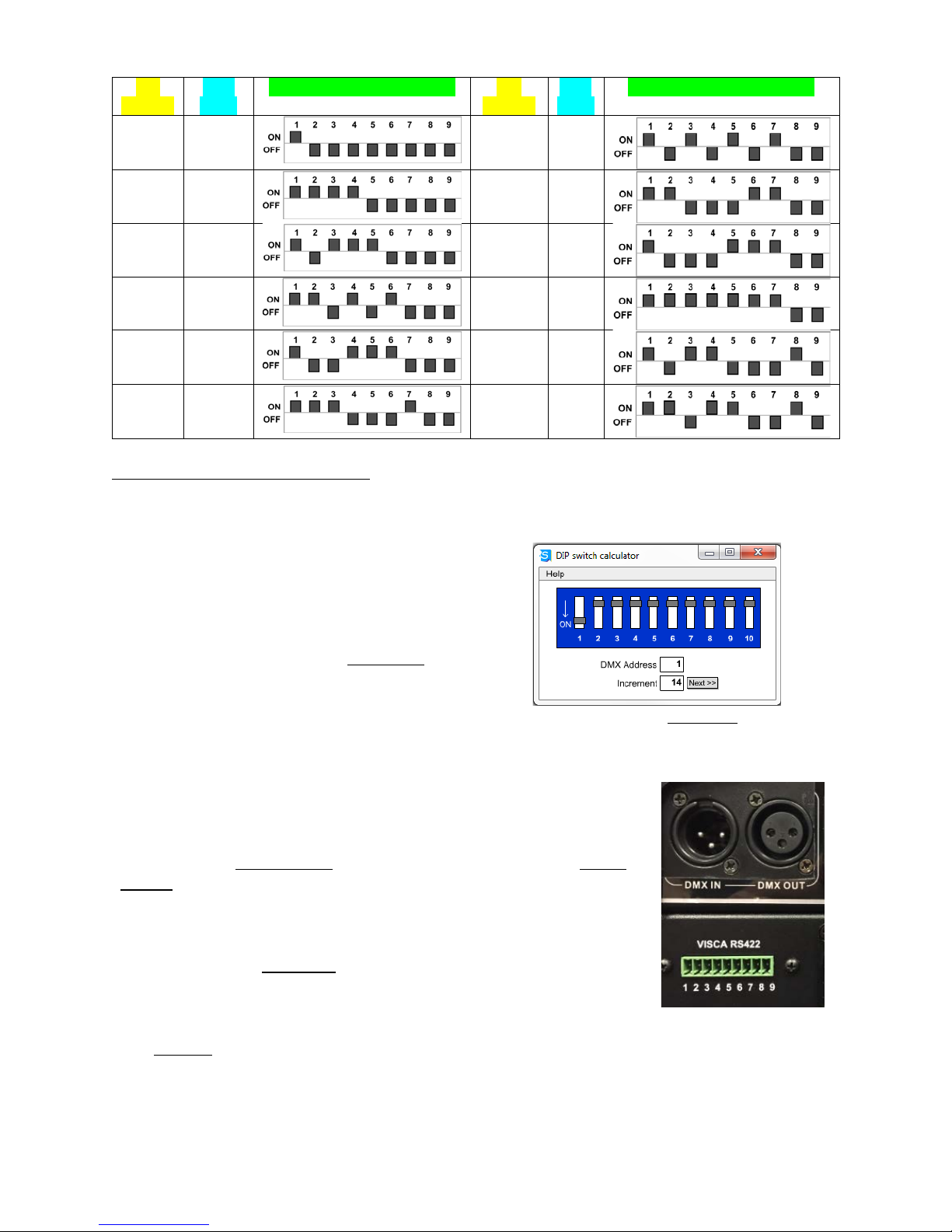
To configure additional PTX heads, select and enter the DMX/VISCA ID for each head.
Increment each head based on the number of channels in the profile. For 14 channels the
second fixture would be DMX ID 15, the third 29, etc. as indicated in the graphic.
To help you determine appropriate DIP
settings we’ve included a small file,
dipcalc.exe, on the USB card included in the
PTX box. It’s also available on the Ctrl+R
page on the website. Use the Increment
function with the profile channel number to
obtain consecutive DMX addresses.
After you’ve entered the Increment value, click
to obtain addresses, starting from the
DMX Address you enter in the field.
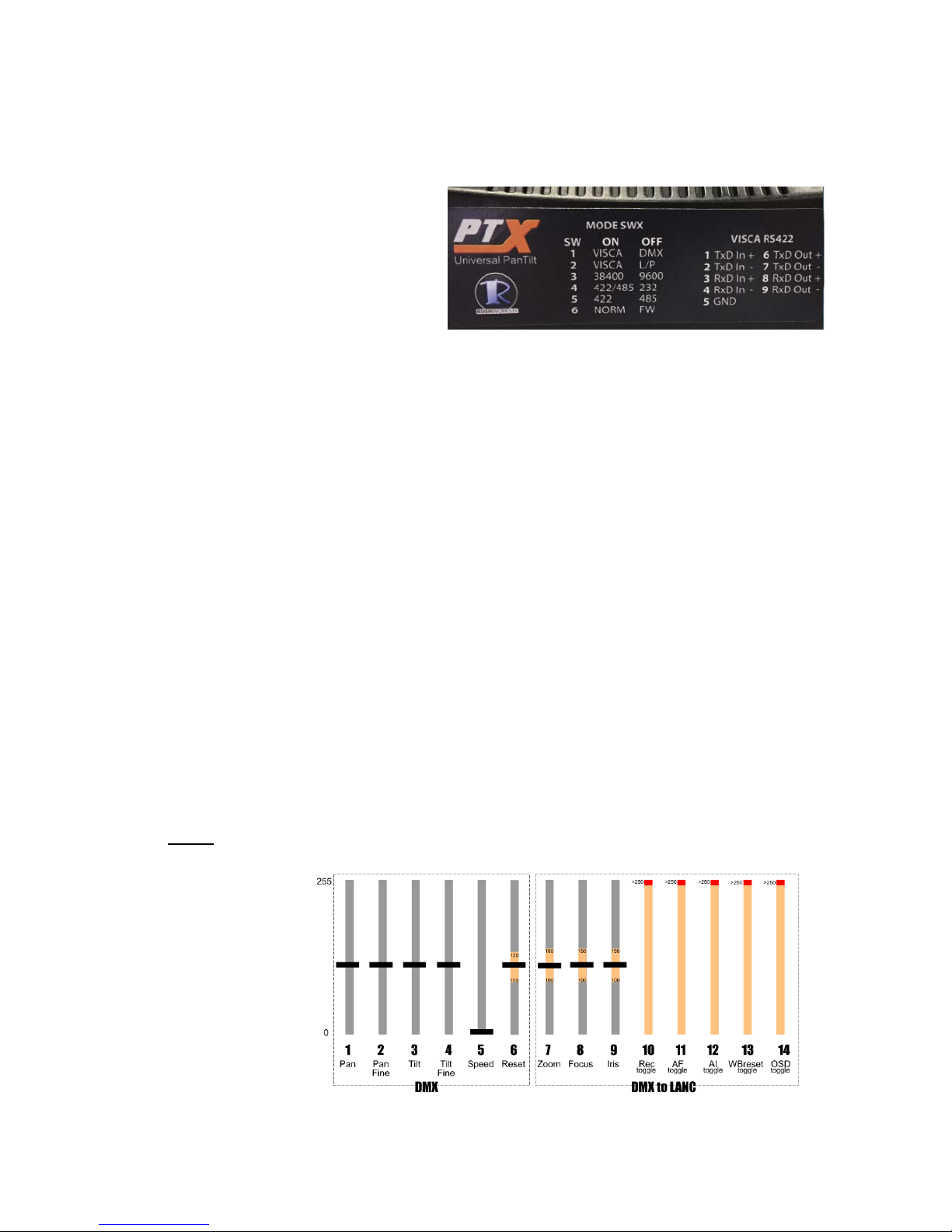
SETTING THE MODE DIP SWITCH
There are currently TWO methods of controlling the PTX Universal
PanTilt Heads: DMX control from a console or software; and VISCA
control, using a number of controllers that support VISCA serial
control output.
It’s important to understand the distinction between CONTROLLER
and CAMERA. The Controller is the device that connects to either the
DMX IN (XLR), or the green 9-pin Phoenix connector that supports
two-way RS-422 serial communications with the controller.
The Camera is a camera or camcorder connected to the tilt plate on the PTX fixture. Cameras
are controlled using the internal protocols supported by the PTX. These include LANC,
Panasonic Remote and VISCA connections.
LANC is a single-wire, one-way digital protocol used by Sony, Canon, JVC and Blackmagic on
many of their cameras.
Panasonic Remote is a two-wire, one-way analog protocol for many Panasonic models.