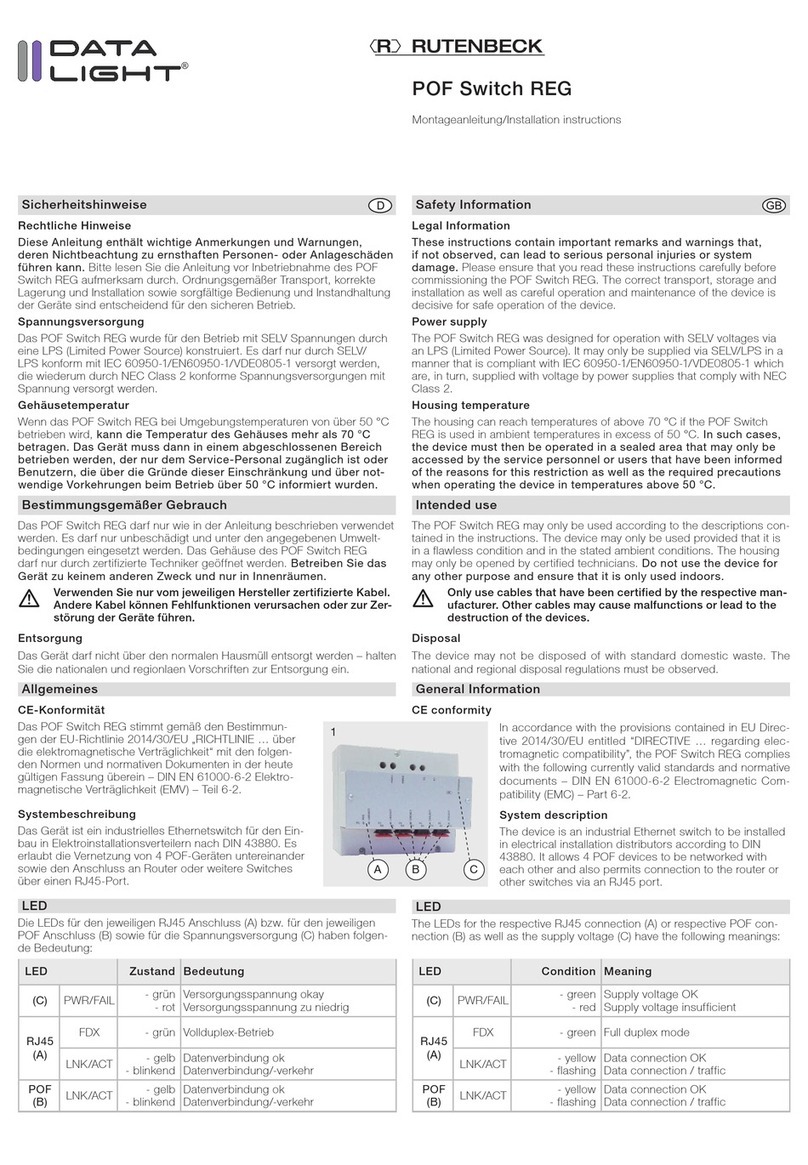
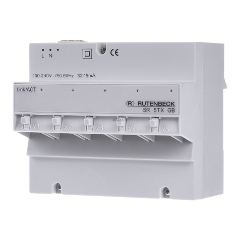
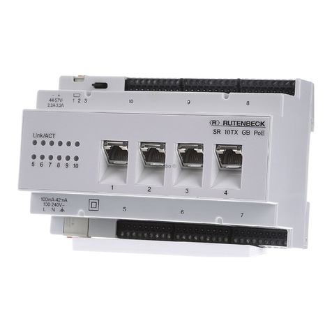
Rutenbeck SV USB 50 Series User manual

Bei Installationsfragen
Kundenservice:
(03 69 25) 9 00 90
kundenservice@rutenbeck.de
SV USB 50
Bedienungsanleitung/
Operating Instructions

2
Allgemeines
Diese Bedienungsanleitung
gehört zum Signalverstärker SV
USB 50. Sie enthält wichtige
Hinweise zur Handhabung des
Geräts.
Achten Sie hierauf, auch wenn
Sie das Gerät an Dritte weiterge-
ben. Bewahren Sie diese Bedie-
nungsanleitung zum Nachlesen
auf.
Lieferumfang
1 SV USB 50 176 101 03
bestehend aus
1 SV USB 50 Einspeisung und
1 SV USB 50 Hub
1 Netzteil 7,5V 0,5A
1 m Kabel USB ST-ST TypA -> TypB
Bedienungsanleitung
Bestimmungsgemäße Verwendung
USB-Verlängerungskabel sind
bis zu einer maximalen Länge
von 5 m spezifiziert. Mit dem
SV USB 50 und der entspre-
chenden Cat.5-Verlängerung
kann ein Strecke bis max. 50 m
überbrückt werden. Der SV
USB 50 dient der Übertragung
der USB-Signale, so dass über
eine Entfernung von maximal
50 m ein Weiterarbeiten mit dem
angeschlossenen Eingabegerät
möglich ist.
Vorbereitung
1. Verbinden Sie mittels des
im Lieferumfang enthaltenen
USB-Anschlusskabels den
Eingang Upstream des SV
USB 50 Einspeisung mit dem
USB-Eingang Ihres Compu-
ters (siehe Bild 1).
2. Verbinden Sie den SV USB
50 Einspeisung und den SV
USB 50 Hub mit einer Ca.5-
Leitung.
3. Verbinden Sie das Eingabege-
rät (z. B. USB-Maus) mit einem
Eingang der vier Downstream-
Ports (Port1,...,Port4) des SV
USB 50 Hub (siehe Bild 2).
4. Stecken Sie den Stecker des
Netzteils in die Buchse „Pow-
er“ des SV USB 50 Hub.
5. Schließen Sie das Netzteil an
die Stromversorgung an.
Inbetriebnahme
Nach der korrekten Installa-
tion meldet sich das System
als Standard-USB-HUB (USB\
VID_04CC&PID_1122\...) beim
Computer an.
Die Leuchtdiode an der Cat.5-
Buchse zeigt den Datenverkehr
auf der Cat.5-Leitung an.
Die korrekte Initialisierung des
SV USB 50 wird durch Auf-
leuchten der LED am USB-Port1
angezeigt. Kurzzeitiges Aufblin-
ken der LED signalisiert den
Datenverkehr.
Automatische Stromüberlast-
Abschaltung
Der SV USB 50 ist mit einer
automatischen Stromüberlast-
Abschaltung ausgestattet. Bei
einer Strombelastung von mehr
als 500 mA schaltet der SV USB
50 ab und meldet diesen Status
an den Computer.
Die maximale Anzahl
hintereinander geschal-
teter SV USB 50 in
USB-Systemen ist
begrenzt. Abhängig von dieser
Anzahl ändert sich auch die
maximal anwendbare Kabellänge
der Cat.5-Leitung. Schließen Sie
daher den SV USB 50 Einspei-
sung direkt an den USB-Port
des Computers an.
Keine Unterstützung
des USB-2.0-Mode mit
einer Übertragungsrate
von 480 Mbit/s!
UpstreamCAT5
CE
Port 1 Port 2 Port 3 Port 4 Power
CAT5
CE
Bild 1 Frontblende SV USB 50 Einspeisung
Bild 2 Frontblende SV USB 50 Hub
3
Funktionsstörung
Sollte der SV USB 50 einmal
nicht funktionieren, kann es an
folgendem Problem liegen:
- Prüfen Sie zunächst, ob die
Energieverwaltung für den SV
USB 50 Hub eingeschaltet ist.
Hierfür verbinden Sie ein USB-
Gerät mit dem SV USB 50 Hub
und diesen dann mit dem SV
USB Einspeisung. Danach ver-
binden Sie den SV USB 50 Ein-
speisung mit Ihrem Computer.
- Ziehen Sie nun das USB-Gerät
aus dem SV USB 50 Hub.
Achten Sie auf die Leuchtdiode
neben Port1.
Erlischt die Leuchtdiode, ist die
Energieversorgung für den USB
Hub ausgeschaltet, und es kann
auch nachträglich kein USB-
Gerät mit diesem Hub verbun-
den und erkannt werden.
- Öffnen Sie die Systemsteue-
rung auf Ihrem Computer:
ÆStart
ÆEinstellungen
ÆSystemsteuerung
ÆSystem
ÆHardware
ÆGeräte-Manager
ÆUSB-Controller
Hier können Sie nun die Energie-
versorgung für den benötigten
USB-Hub Ihres Rechners ein-
stellen. (siehe Bild 4).
Deaktiviert man dieses Häkchen
„Computer kann Gerät ausschal-
ten, um Energie zu sparen“,
treten generell keine Probleme
auf.
Erlischt die Leuchtdiode neben
Port1 nicht, ist Ihr Computer
bereits korrekt eingestellt, und
Sie können problemlos mit dem
SV USB 50 arbeiten.
Inbetriebnahme
Bild 3 Anwendungsbeispiel
Bild 4 Systemeinstellungen

4
Technische Daten
SV USB 50 Einspeisung SV USB 50 Hub
Mechanische Eigenschaften
Gewicht: ca. 120 g ca. 135 g
Breite: 125 mm
Tiefe: 69 mm
Höhe: 29 mm
Übertragungstechische Eigenschaften
Übertragungslänge: max. 50 m
Umgebungsbedingungen
Betriebstemperatur: +5°C bis +40°C
Rel. Luftfeuchtigkeit: max. 85%
Luftdruck: 600 bis 1000 hPA
Garantie
Wir garantieren für 2 Jahre nach
Kaufdatum (Quittungsbeleg) bei
sachgemäßer Installation und
Behandlung die einwandfreie
Funktion des Gerätes.
Bei telefonischen Rückfragen
wenden Sie sich bitte an die
Rutenbeck-Hotline:
(03 69 25) 9 00 90
Sicherheit
Diese Bedienungsanleitung
enthält grundlegende Hinweise,
die Sie bei der Bedienung des
SV USB 50 beachten müssen.
Halten Sie sich genau an die
Anweisungen, um Fehler zu
vermeiden. Lesen Sie diese
Bedienungsanleitung deshalb
unbedingt, bevor Sie mit dem SV
USB 50 arbeiten.
Öffnen Sie niemals das Gehäuse
des SV USB 50! Mit dem Öffnen
endet sofort jeglicher Garantie-
anspruch!
Eine Verwendung ist
nur in geschlosse-
nen Räumen, also
nicht im Freien,
erlaubt. Der Kontakt
mit Feuchtigkeit ist unbedingt zu
vermeiden.
Spannungs- und
Stromschwankungen
beim Anschluss des
SV USB 50 können
elektronische Bautei-
le beschädigen. Verbinden Sie
den SV USB 50 mit den Compu-
tern, bevor Sie die Spannungs-
versorgung anschließen.
Entsorgung
Bitte leisten Sie Ihren Beitrag zur
Entlastung der Umwelt, indem
Sie dieses Gerät nach Ende
seiner Nutzung einer umweltge-
rechten Verwertung zuführen.
Auf keinen Fall sollten Sie das
Gerät in den unsortierten Sied-
lungsmüll geben.
Bei unsachgemässer Beseiti-
gung von Elektroschrott könnten
gefährliche Stoffe unsere Umwelt
und unser aller Gesundheit
beeinträchtigen.
Im Falle einer Reklamation oder
einer nicht behebbaren Funkti-
onsstörung wenden Sie sich bitte
an Ihren Fachhändler oder sen-
den Sie das Gerät mit Kaufbeleg
und einer kurzen Fehlerbeschrei-
bung an nachstehende Anschrift:
Rutenbeck-Kundenservice
Gewerbegebiet
Im Meilesfeld 5
99819 Marksuhl
Telefon (03 69 25) 9 00 90
Telefax (03 69 25) 9 00 92
Instandsetzung
Herstellererklärung
Wir, die Wilhelm Rutenbeck
GmbH & Co. KG, erklären in
alleiniger Verantwortung, dass
sich der SV USB 50 in Überein-
stimmung mit den Anforderungen
und Vorschriften der Richtlinien
2004/108/EG und 2006/95/EG
befindet.
Die vollständige Konformitäts-
erklärung finden Sie unter www.
rutenbeck.de im Downloadbe-
reich.

5
General
These instructions for use
belong to this product. They
contain important information on
handling the device. Please pay
attention to this, even if you are
passing the device on to third
parties. Keep these instructions
for use for future reference.
Scope of Delivery
1 SV USB 50 176 101 03
consisting of
1 SV USB 50 PC and
1 SV USB 50 Hub
1 power supply 7,5V 0,5A
1 m cable USB ST-ST TypA -> TypB
operating instructions
Intended Application
USB extension cables are spe-
cified to a maximum length of
5 m. Using the SV USB and the
appropriate Cat.5 extension, a
distance of upto max. 50 m can
be bridged. The SV USB is used
to transmit USB signals and can
therefore extend the function
of the connected input device
across a maximum distance of
50 m.
Starting the Operation
1. Using the USB connection
included in delivery, connect
the ”Upstream“ input of the SV
USB PC with the ”USB“ input
on your computer (see Diag 1).
2. Connect the SV USB PC and
-Hub with a Cat.5 cable.
3. Connect the USB (input or
output) device (e.g. USB
mouse) with one of the inputs
on the four Downstream Ports
(Port1,...,Port4) of the SV USB
Hub.
4. Insert the power supply plug
into the ”Power“ socket of the
SV USB Hub. Connect the
power supply to the mains.
Installation
Once the device has been suc-
cessfully installed, the system
displays Standard-USB-HUB
(USB\VID_04CC&PID_1122\...)
on the computer.
The lights on the Cat.5 socket
display data traffic on the Cat.5
cable.
Correct initialisation of the HUB
is displayed via the LED on the
USB Port1. Rapid flashing of the
LED indicates data traffic.
Automatic power surge pro-
tection
The SV USB Hub has an auto-
matic power surge protection. If
there is a power surge of more
than 500 mA, the SV USB Hub
switches off and sends this
information to the computer.
The maximum number
of cascaded Hubs in
USB systems is limited.
The maximum cable
length of the Cat.5 cable varies
depending on this number. This
is why the SV USB PC must be
connected directly to the USB
Port of the computer.
No support of the
USB 2.0 Mode with a
transmission rate of
480 Mbit/s.
UpstreamCAT5
CE
Port 1 Port 2 Port 3 Port 4 Power
CAT5
CE
Figure 1 Front panel SV USB 50 PC
Figure 2 Front panel SV USB 50 Hub

6
Malfunction
If the SV USB 50 should not
work properly it could be the fol-
lowing problem:
Please check first, if the power
management for the USB Hub
is switched on. For this connect
a USB device with the SV USB
50 Hub and this one then with
the SV USB 50 PC. Afterwards
connect the SV USB 50 PC with
your computer.
Now unplug the USB device out
of the SV USB 50 next to Port1.
If the LED extinguishes, the
power supply for the USB Hub is
switched off, and no USB device
afterwards can be connected
with this Hub and be recognis-
ed.
To resolve this problem, open
the control panel on your com-
puter:
ÆStart
ÆSettings
ÆControl panel
ÆSystem
ÆHardware
ÆDevice Manager
ÆUSB-Controller
Now you can set die power
supply for the required USB Hub
of your computer.
If disabled (not checked)
„Computer can switch off device
to save Energy“,
generally no problems occur.
If the LED next to Port1 does
not extinguish, your computer
is already set properly, and you
can work with the SV USB 50
without difficulty.
Installation
Figure 4 Power management of the computer
Figure 3 Application example

7
Technical Data
SV USB 50 PC SV USB 50 Hub
Mechanical characteristics
Weight: ca. 120 g ca. 135 g
Width: 125 mm
Depth: 69 mm
Hight: 29 mm
Transmission characteristics
Transmission length: max. 50 m
Environmental conditions
Operating temperature: +5°C to +40°C
Rel. humidity: max. 85%
Air pressure: 600 to 1000 hPA
Warranty
We guarantee the perfect func-
tion of the SV USB for 2 years
after date of purchase (receipt)
assuming that it was professio-
nally installed and operated.
Safety
These instructions for use con-
tain fundamental instructions
that you must observe when
operating the SV USB. Follow
the instructions precisely to
avoid errors. You must therefore
read these instructions for use
before working with the SV USB.
Never open the housing of the
SV USB. All warranty claims
immediately become invalid
upon opening.
Use is only permitted
in enclosed areas,
i.e. not in the open.
Contact with moistu-
re must be avoided.
Voltage and current
fluctuations when
connecting the SV
USB may damage
electronic compo-
nents. Connect the SV USB to
the computers before connec-
ting the power supply.
Disposal of Waste
Please take part in protecting
our environment by properly
recycling this device at end of
lifetime.
You should never dispose this
device in the regular garbage.
Improper disposal of electronic
waste can release dangerous
substances into the environment
and affect public health.
In case of a malfunction consult
the expert who installed the SV
USB or send it with the receipt
an a short description of
the malfunction to the following
address:
Rutenbeck-Kundenservice
Gewerbegebiet
Im Meilesfeld 5
99819 Marksuhl
Germany
Phone +49 36925 90090
Fax +49 36925 90092
Service
Manufacturer‘s Declaration
We, Wilhelm Rutenbeck GmbH
& Co. KG, declare on our sole
responsibility, that the SV USB is
in compliance with the essential
requirements and provisions of
the directives 2004/108/EG and
2006/95/EG.
The complete declaration of con-
formity can be found under
www.rutenbeck.de in the down-
load-sector.

© Wilhelm Rutenbeck GmbH & Co. KG 2012 · 10511301 · Technische Änderungen vorbehalten/Subjected to technical changes · Stand/Status 04.12
Niederworth 1-10
58579 Schalksmühle
Telefon (0 23 55) 82-0
Telefax (0 23 55) 82-105
www.rutenbeck.de
Bei technischen Fragen:
Rutenbeck-Kundenservice
Hotline (03 69 25) 9 00 90
Telefax (03 69 25) 9 00 92
This manual suits for next models
2
Table of contents
Languages:
Other Rutenbeck Switch manuals

Rutenbeck
Rutenbeck SR 10TX GB User manual

Rutenbeck
Rutenbeck SR 5TX GB User manual

Rutenbeck
Rutenbeck POF Switch REG User manual

Rutenbeck
Rutenbeck USB 4xUp User manual

Rutenbeck
Rutenbeck TCR IP 4 User manual

Rutenbeck
Rutenbeck REG-Switch SR 10TX GB PoE User manual

Rutenbeck
Rutenbeck REG-Switch SR 5 User manual

Rutenbeck
Rutenbeck SR 2TX/2SC User manual
Popular Switch manuals by other brands

Cisco
Cisco SLM2008 - Small Business Smart Switch datasheet

ABB
ABB NE802 user manual

Omnitron Systems
Omnitron Systems RuggedNet 10GPoEBT/Si user manual

Enabling Devices
Enabling Devices Foot Switch user guide

Phoenix Contact
Phoenix Contact FL SWITCH GHS 12G/8 user manual

Cisco
Cisco 550XG series quick start guide