POF Switch REG
Montageanleitung/Installation instructions
Safety Information
Legal Information
These instructions contain important remarks and warnings that,
if not observed, can lead to serious personal injuries or system
damage. Please ensure that you read these instructions carefully before
commissioning the POF Switch REG. The correct transport, storage and
installation as well as careful operation and maintenance of the device is
decisive for safe operation of the device.
Power supply
The POF Switch REG was designed for operation with SELV voltages via
an LPS (Limited Power Source). It may only be supplied via SELV/LPS in a
manner that is compliant with IEC 60950-1/EN60950-1/VDE0805-1 which
are, in turn, supplied with voltage by power supplies that comply with NEC
Class 2.
Housing temperature
The housing can reach temperatures of above 70 °C if the POF Switch
REG is used in ambient temperatures in excess of 50 °C. In such cases,
the device must then be operated in a sealed area that may only be
accessed by the service personnel or users that have been informed
of the reasons for this restriction as well as the required precautions
when operating the device in temperatures above 50 °C.
Intended use
The POF Switch REG may only be used according to the descriptions con-
tained in the instructions. The device may only be used provided that it is
in a flawless condition and in the stated ambient conditions. The housing
may only be opened by certified technicians. Do not use the device for
any other purpose and ensure that it is only used indoors.
Only use cables that have been certified by the respective man-
ufacturer. Other cables may cause malfunctions or lead to the
destruction of the devices.
Disposal
The device may not be disposed of with standard domestic waste. The
national and regional disposal regulations must be observed.
General Information
CE conformity
In accordance with the provisions contained in EU Direc-
tive 2014/30/EU entitled “DIRECTIVE … regarding elec-
tromagnetic compatibility”, the POF Switch REG complies
with the following currently valid standards and normative
documents – DIN EN 61000-6-2 Electromagnetic Com-
patibility (EMC) – Part 6-2.
System description
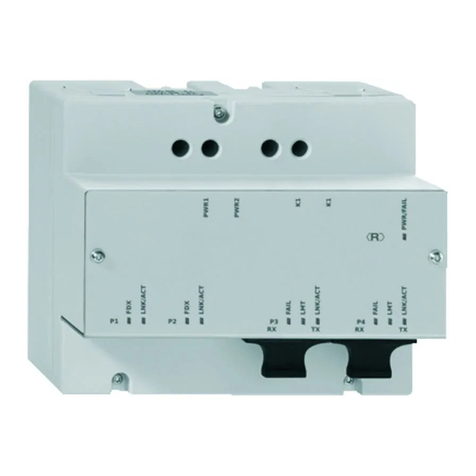
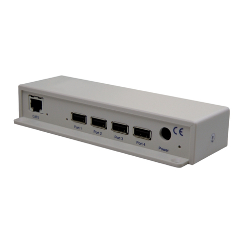
The device is an industrial Ethernet switch to be installed
in electrical installation distributors according to DIN
43880. It allows 4 POF devices to be networked with
each other and also permits connection to the router or
other switches via an RJ45 port.
LED
The LEDs for the respective RJ45 connection (A) or respective POF con-
nection (B) as well as the supply voltage (C) have the following meanings:
Sicherheitshinweise
Rechtliche Hinweise
Diese Anleitung enthält wichtige Anmerkungen und Warnungen,
deren Nichtbeachtung zu ernsthaften Personen- oder Anlageschäden
führen kann. Bitte lesen Sie die Anleitung vor Inbetriebnahme des POF
Switch REG aufmerksam durch. Ordnungsgemäßer Transport, korrekte
Lagerung und Installation sowie sorgfältige Bedienung und Instandhaltung
der Geräte sind entscheidend für den sicheren Betrieb.
Spannungsversorgung
Das POF Switch REG wurde für den Betrieb mit SELV Spannungen durch
eine LPS (Limited Power Source) konstruiert. Es darf nur durch SELV/
LPS konform mit IEC 60950-1/EN60950-1/VDE0805-1 versorgt werden,
die wiederum durch NEC Class 2 konforme Spannungsversorgungen mit
Spannung versorgt werden.
Gehäusetemperatur
Wenn das POF Switch REG bei Umgebungstemperaturen von über 50 °C
betrieben wird, kann die Temperatur des Gehäuses mehr als 70 °C
betragen. Das Gerät muss dann in einem abgeschlossenen Bereich
betrieben werden, der nur dem Service-Personal zugänglich ist oder
Benutzern, die über die Gründe dieser Einschränkung und über not-
wendige Vorkehrungen beim Betrieb über 50 °C informiert wurden.
Bestimmungsgemäßer Gebrauch
Das POF Switch REG darf nur wie in der Anleitung beschrieben verwendet
werden. Es darf nur unbeschädigt und unter den angegebenen Umwelt-
bedingungen eingesetzt werden. Das Gehäuse des POF Switch REG
darf nur durch zertifizierte Techniker geöffnet werden. Betreiben Sie das
Gerät zu keinem anderen Zweck und nur in Innenräumen.
Verwenden Sie nur vom jeweiligen Hersteller zertifizierte Kabel.
Andere Kabel können Fehlfunktionen verursachen oder zur Zer-
störung der Geräte führen.
Entsorgung
Das Gerät darf nicht über den normalen Hausmüll entsorgt werden – halten
Sie die nationalen und regionlaen Vorschriften zur Entsorgung ein.
Allgemeines
CE-Konformität
Das POF Switch REG stimmt gemäß den Bestimmun-
gen der EU-Richtlinie 2014/30/EU „RICHTLINIE … über
die elektromagnetische Verträglichkeit“ mit den folgen-
den Normen und normativen Dokumenten in der heute
gültigen Fassung überein – DIN EN 61000-6-2 Elektro-
magnetische Verträglichkeit (EMV) – Teil 6-2.
Systembeschreibung
Das Gerät ist ein industrielles Ethernetswitch für den Ein-
bau in Elektroinstallationsverteilern nach DIN 43880. Es
erlaubt die Vernetzung von 4 POF-Geräten untereinander
sowie den Anschluss an Router oder weitere Switches
über einen RJ45-Port.
LED
Die LEDs für den jeweiligen RJ45 Anschluss (A) bzw. für den jeweiligen
POF Anschluss (B) sowie für die Spannungsversorgung (C) haben folgen-
de Bedeutung:
1
CBA
LED Zustand Bedeutung
(C) PWR/FAIL - grün
- rot
Versorgungsspannung okay
Versorgungsspannung zu niedrig
RJ45
(A)
FDX - grün Vollduplex-Betrieb
LNK/ACT - gelb
- blinkend
Datenverbindung ok
Datenverbindung/-verkehr
POF
(B) LNK/ACT - gelb
- blinkend
Datenverbindung ok
Datenverbindung/-verkehr
LED Condition Meaning
(C) PWR/FAIL - green
- red
Supply voltage OK
Supply voltage insufficient
RJ45
(A)
FDX - green Full duplex mode
LNK/ACT - yellow
- flashing
Data connection OK
Data connection / traffic
POF
(B) LNK/ACT - yellow
- flashing
Data connection OK
Data connection / traffic

