manuals.online logo
Brands
  1. Home
  2. •
  3. Brands
  4. •
  5. Rutenbeck
  6. •
  7. Wireless Access Point
  8. •
  9. Rutenbeck Up-Accesspoint UAE 2,4GHz 300M rw User manual

Rutenbeck Up-Accesspoint UAE 2,4GHz 300M rw User manual

Up-Accesspoint UAE 2,4GHz 300M rw
Montageanleitung / Mounting instructions
Safety Instructions
Electrial power supply!
Hazardous to life and fire danger due to electrical voltage
of 230 V!
Work on the 230 V supply may only be carried out by authorized
electricians!
Intended Use
Different operating modes allow the system to function as an access point
or repeater to increase the range of a WLAN network. In addition, WLAN
appliances which do not have their own WLAN interface can be adapted
to the network.
Only use this device for these purposes and operate indoors.
These installation instructions and the relevant operating instruc-
tions are an integral part of the appliance. They must be observed
during installation and must be made available to the user after
installation.
General
The accesspoint extends the use of modern mobile network technologies
with low power consumption and low-radiation emisson.
Individual function settings allow individual access points to be delimited
from one another, thus avoiding overcoupling of the WLAN zones and
losses in data rates.
Detailed user information can be found at www.rutenbeck.de.
Installation location
The following conditions must be met in order to ensure
an ideal functionality of the accesspoint:
- Ensure that the device is only correctly installed into
walls and observe an assembly height of between 30
and 130 cm.
- When used as a repeater or when using the mesh
function, the signal strength of the signal to be ampli-
fied must be ≥ 70 dBm at the installation location.
Installation
Connection of Power Supply
Warning! Hazardous for life! Disconnect the
main voltage before connection.
The standard five safety rules according to DIN VDE 0105 apply:
1 Disconnect from the power supply
2 Secure against reconnection
3 Check that equipment is dead
4 Earth and short circuit
5 Cover or screen off all live adjacent parts
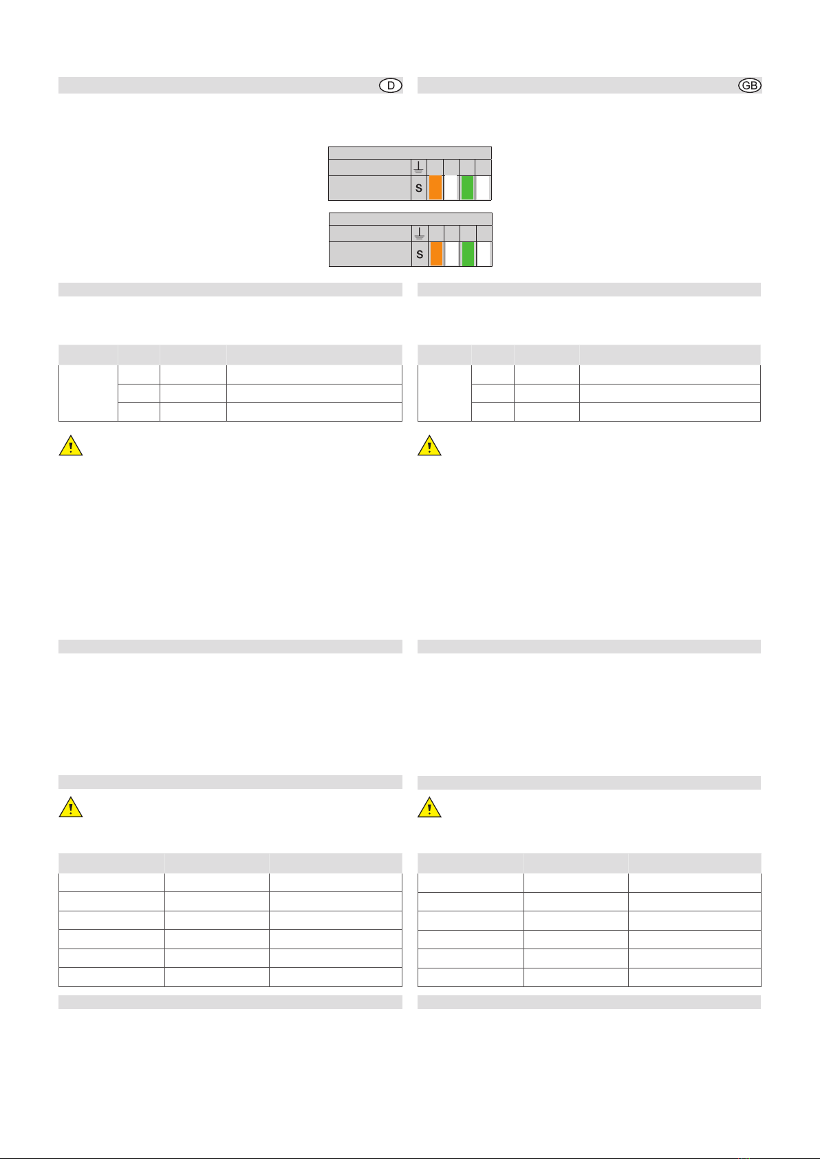
Connect power (for releasing press the connector block –
max. cable diameter: 1.5mm2, cable stripping length:
8mm – and unplug the wire) – see figure 1.
Loss of warranty failure.
In order to avoid interference of the network by distur-
bances/alterations in the range of the 230 V installation
please always disconnect the power supply of the active
devices as accesspoint of those of other power consum-
ers (e. g. microwave, vacuum cleaner).
Use a separate circuit e. g. by applying a line-protective
or line disconnecting switch or an insulated overvoltage
protection (C-arrester) and clearly label the circuit as well
as the belonging jacks clearly, e. g. with ‘EDP’.
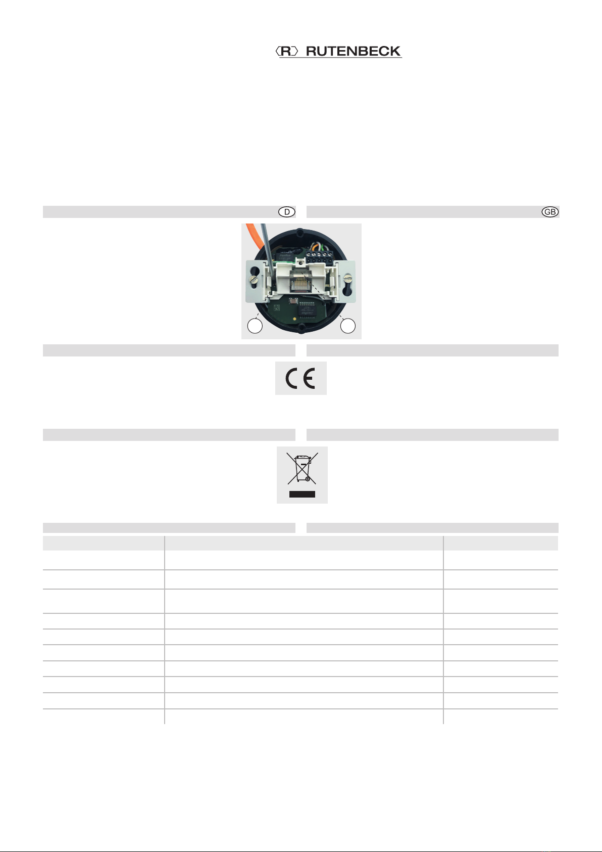
Connection of network cable to the
screw terminal block
1 Pull the cable preferably from top of the installation
box (B).
Sicherheitshinweise
Elektrische Spannung!
Lebensgefahr und Brandgefahr durch elektrische Spannung
von 230V möglich.
Arbeiten am 230-V-Netz dürfen nur durch Elektrofachpersonal ausge-
führt werden!
Bestimmungsgemäßer Gebrauch
Unterschiedliche Betriebsarten ermöglichen die Funktion als Accesspoint
oder als Repeater um die Reichweite im WLAN-Netzwerk zu erhöhen. Dar-
überhinaus können WLAN-Geräte an das Netzwerk adaptiert werden, die
über keine eigene WLAN-Schnittstelle verfügen. Benutzen Sie das Gerät
zu keinem anderen Zweck. Betreiben Sie das Gerät nur in Innenräumen.
Diese Montageanleitung und die zugehörige Bedienungsanleitung
sind wesentlicher Bestandteil des Gerätes. Sie sind beim Einbau
zu beachten und müssen dem Anwender nach dem Einbau zur
Verfügung gestellt werden.
Allgemeines
Der Up-Accesspoint erweitert die Nutzungsmöglichkeiten moderner,
mobiler Netzwerktechnologien bei geringer Leistungsaufnahme und strah-
lungsarmer Funkemission. Individuelle Funktionseinstellungen erlauben
die Abgrenzung einzelner Accesspoints untereinander und vermeiden so
Überkopplungen der WLAN-Bereiche und Einbußen bei den Datenraten.
Ausführliche Benutzerinformationen finden Sie unter www.rutenbeck.de.
Einbauort
Für eine optimale Funktion des Up-Accesspoints müssen
folgende Bedingungen erfüllt sein:
- Bauen Sie das Gerät nur bestimmungsgemäß in
Wände ein und halten Sie eine Montagehöhe
zwischen 30 und 130 cm ein.
- Bei Verwendung als Repeater oder bei Nutzung der
Mesh-Funktion muss die Signalstärke des zu ver-
stärkenden Signals am Einbauort ≥ 70 dBm sein.
Installation
Anschließen der Netzspannung
Lebensgefahr! Schalten Sie die Netzspannung
vor dem Anschließen frei.
Beachten Sie bei Arbeiten in und an elektrischen Anlagen die fünf Sicher-
heitsregeln nach DIN VDE 0105:
1 Freischalten
2 Gegen Wiedereinschalten sichern
3 Spannungsfreiheit allpolig feststellen
4 Erden und kurzschließen
5 Benachbarte unter Spannung stehende Teile abdecken.
Schließen Sie die Netzspannung mittels der Steckklemmen
(Leitungsdurchmesser max.1,5 mm2, Abisolierlänge des
Leiters = 8mm) an. Zum Lösen drücken Sie die Rastnase
und ziehen Sie die Ader heraus (s. Abbildung 1).
Bei Nichtbeachtung Garantieverlust!
Um eine Beeinflussung des Netzwerks durch Störungen/
Veränderungen im Bereich der 230 V-Installation zu ver-
meiden, trennen Sie stets die Spannungsversorgung akti-
ver Komponenten sowie der Datenendgeräte (PC usw.) von
denen anderer Verbraucher (z. B. Mikrowelle, Staubsauger).
Verwenden Sie eigene Stromkreise, indem Sie z.B.
einen Leitungstrenn- oder -schutzschalter einsetzen und
ggf. einen geeigneten Überspannungsschutz (C-Ableiter).
Kennzeichnen Sie den Stromkreis sowie die zugehörigen
Steckdosen eindeutig, z.B. mit „EDV“.
Anschließen des Netzwerk-Kabels an die
Schraubklemmleiste
1 Ziehen Sie das Kabel vorzugsweise oben in die Einbau-
dose ein (B).
Technical Support
+4 9 2355 82-111
[email protected]
Commercial Support
+49 2355 82-137
[email protected]
|––– 8 m m ––– |
1
A
2
3D
C
B
2 Kürzen Sie das Kabel so, dass ca. 90 mm vom Dosenboden an
verbleiben.
3 Isolieren Sie das Kabel auf ca. 80 mm ab.
4 Ziehen Sie den 5-poligen Schraubklemmblock ab
und legen Sie die Adern gemäß Farbcode auf.
VErhalten Sie die Paarschirmung und die Ver-
drillung der Paare so lang wie möglich!
VVerdrillen Sie den Gesamtschirm und ver-
wenden Sie ggf. eine 1-mm-Aderendhülse.
VBeachten Sie die gleiche Belegung im Ran-
gierfeld und an der Dose!
5 Setzen Sie dann den Klemmblock auf die
Stiftleiste.
Erstinbetriebnahme
Nach Zuschaltung der Stromversorgung ist der Up-Accesspoint
dann nach ca. einer Minute mit den Werkseinstellungen betriebsbe-
reit. Dies wird über die LEDs (Abb. 3, C und D) wie folgt signalisiert:
Variante LED Zustand Bedeutung
300M
mittig leuchtet LAN (orange) bzw. WLAN (blau)
mittig blinkt Datenverkehr
links leuchtet angeschlossenes Datenkabel
Bitte beachten Sie, dass jeder Up-Accesspoint individuell
programmiert werden muss!
Über die Funktion ‚Fernsteuerung‘ ist die Änderung der
Grundeinstellungen über jeden mit dem Netzwerk ver-
bundenen Accesspoint möglich.
Für die Erstinbetriebnahme verbinden Sie den Accesspoint vorzugs-
weise über ein Patchkabel mit der LAN-Schnittstelle Ihres PCs und
konfigurieren Sie ihn nach Ihren Wünschen.
Ausführliche Informationen zur Erstinbetriebnahme finden Sie im
Download-Bereich der Webseite www.rutenbeck.de
Sie erreichen das Gerät bei Werkseinstellungen unter:
IP-Adresse: http://192.168.0.5
Passwort: admin
WLAN SSID: Rutenbeck
Schlüssel: wireless123
Zugriff ohne Sicherheitszertifikat
Der Zugriff auf das Gerät erfolgt über das Protokoll ‚https‘. Da der
Accesspoint kein eigenes Sicherheitszertifikat besitzt, wird die
Verbindung beim Aufruf über den Browser zunächst als unsicher
eingestuft. Insofern müssen Sie diese Verbindung explizit zulassen
und ggf. für den weiteren Zugriff eine Ausnahmeregelung einrichten.
Die Vorgehensweise ist abhängig vom jeweiligen Browser.
Genaue Informationen zum Zugriff auf einen Accesspoint ohne
Sicherheitszertifikat finden Sie ebenfalls im zuvor erwähnten Down-
load-Bereich.
Individualisierung / Datenschutz
Direkt bei der ersten Inbetriebnahme sollten aus Gründen
des Datenschutzes, aber auch aus Gründen der Netzwerk-
sicherheit folgende Einstellungen individualisiert und doku-
mentiert werden.
Werkseinstellung geändert auf
admin Gerätepasswort
192.168.0.5 IP-Adresse
255.255.255.0 Subnetz-Maske 255.255.255.0
Rutenbeck WLAN SSID
wireless123 WLAN Schlüssel
Accesspoint Betriebsart
Reset
Sie haben drei Möglichkeiten, den Up-Accesspoint zurückzusetzen:
VMittels Webbrowser unter System > System neu starten
VMittels Reset-Magnet (Art.-Nr. 392 000 10) auf Werkseinstel-
lungen – siehe zugehörige Anleitung
Voder mittels Schlitzschraubendreher
Installation (Fortsetzung) Installation (Continued)
2 Shorten the cable so that approx. 90 mm remain from the instal-
lation box bottom.
3 Strip off the cable sheath to approx. 80 mm.
4 Pull off the 5-pole terminal block and connect the
wires according to the color code on the left.
VLeave the wire pair shielding and the wire
twist for as long as possible!
VTwist the shielding and, if necessary,
use a 1 mm wire end sleeve.
VMake sure the wires are connected accord-
ing to the color code in the patch panel and
on the jack!
5 Place the terminal block on the pin header.
Initial start-up
The accesspoint is ready for operation with the factory settings
approx. one minute after the power supply is switched on. This is
indicated by the LEDs as follows:
Version LED Status Description
300M
centre illuminates LAN (orange) or WLAN (blue)
centre blinks Data traffic
left illuminates connected data cable
Please note that each up-access point has to be pro-
grammed individually!
The ‘Remote control’ function allows the basic settings to be
changed from any access point connected to the network.
For initial start-up, connect the accesspoint to your PC LAN inter-
face, preferably via a patch cable, and configure it according to your
requirements.
Detailed information on initial start-up can be found in the website
download area at www.rutenbeck.de
You can access the appliance with factory settings at:
IP address: http://192.168.0.5
Password: admin
WLAN SSID: Rutenbeck
Key: wireless123
Access without security certificate
The access to the device is via the ‘https’ protocol. Because the
accesspoint does not have its own security certificate, the connec-
tion is initially classified as insecure when accessed via the browser.
So you must explicitly permit this connection and, if necessary, set
up an exception rule for further access. The procedure depends on
the respective browser.
Please refer to the download area mentioned above to find precise
information on how to access an access point without a security
certificate.
Personalisation / data protection
For reasons of data protection, but also for reasons
of network security, the following settings should be
individualised and documented directly on initial
start-up.
Factory setting modified
admin Device password
192.168.0.5 IP address
255.255.255.0 Subnet mask 255.255.255.0
Rutenbeck WLAN SSID
wireless123 WLAN key
Accesspoint Mode
Reset
You have three options for resetting the accesspoint:
VUsing a Web browser under System > Restart system
VUsing a reset magnet (item no. 392 000 10) to factory
settings - see relevant user manual
Vor using a flat tip screwdriver
6 3 2 1
Farbcode
Klemme
Belegung
6 3 2 1
Color code
Terminal
Assignment
© Wilhelm Rutenbeck GmbH & Co. KG · 293 825 · 226104032 · Rut087a · Technische Änderungen vorbehalten / Subjected to technical changes · Stand/Status 11.20
Klagebach 33
58579 Schalksmühle
Telefon +49-(0) 23 55-82-0
Telefax +49-(0) 23 55-82-105
www.rutenbeck.de
[email protected]
Up-Accesspoint UAE 2,4GHz 300M rw
Schutzart IP20 gemäß / according to DIN EN 60529 Protection Class
Betriebstemperatur -5 °C bis / to 40 °C Operating temperature
Anschlüsse RJ 45 (10/100 Mbit/s)
Schraubkontakte / screw terminals Connections
Spannungsversorgung 100–240 V ~ / 50–60 Hz Power supply
Leistungsaufnahme 3 VA Power consumption
Funkbereich 2,4 GHz Wireless range
Funkdatenraten 300 Mbit/s Wireless data rates
Funkstandard IEEE 802.11 b/g/n Wireless standard
Mesh-Standard IEEE 802.11 s Mesh standard
Sicherheit / Verschlüsselung WPA, WPA2, MAC-Filterung / MAC filtering Security / encryption
1 Gehen Sie bei letzterem wie folgt vor:
2 Halten Sie einen Schraubendreher, wie in Abbil-
dung 4 abgebildet, auf den Kontakt (E):
3 für mindestens 2 und höchstens 5 Sekunden
= Reset mit Beibehaltung der Einstellungen
= die mittlere LED (D) blinkt blau
4 für mehr als 5 und höchstens 10 Sekunden
= Reset auf Werkseinstellungen
= die mittlere LED (D) blinkt orange
CE-Erklärung
Wir, die Wilhelm Rutenbeck GmbH & Co. KG erklären in
unserer alleinigen Verantwortung, dass sich dieses Gerät
in Übereinstimmung mit den grundlegenden Anforderungen
und relevanten Vorschriften der zutreffenden EU-Richtlinien
2014/30/EU, 2014/53/EU, 2011/65/EU befindet.
Die vollständige CE-Konformitätserklärung finden Sie unter
www.rutenbeck.de im Download-Bereich.
Entsorgung
Das nebenstehende Symbol weist auf die getrennte Samm-
lung von Elektro- und Elektronikgeräten hin. Dieses Gerät
sowie alle im Lieferumfang enthaltenen Elektronikteile dürfen
gemäß europäischer Richtlinien und deutschem Elektro- und
Elektronikgesetz nicht über den Hausmüll entsorgt werden.
Bringen Sie dieses Gerät nach Ende seiner Nutzung zu einem
zuständigen Sammelsystem für elektrische und elektronische
Altgeräte.
Technische Daten
Reset (Fortsetzung) Reset (Continued)
1 For the latter, proceed as follows:
2 Place a screwdriver on the contact (E) as shown
in figure 4:
3 for minimum 2 and maximum 5 seconds
= reset with retention of setting
= centre LED (D) flashes blue
4 for more than 5 and maximum 10 seconds
= reset to factory settings
= centre LED (D) flashes orange
CE - Declaration of confirmity
We, Wilhelm Rutenbeck GmbH & Co. KG, declare under our
sole responsibility that this device is in conformity with the
essential requirements and the relevant regulations of the
applicable EU-directives 2014/30/EU, 2014/53/EU,
2011/65/ EU.
The complete Declaration of Conformity is available in the Download
Section at www.rutenbeck.com
Disposal
The adjacent symbol indicates separate waste collection for
electrical and electronic devices. In accordance with EU-di-
rectives, all electrical and electronic devices with this symbol
must be disposed in the corresponding separate waste col-
lections and not in the domestic waste. This device as well
as all the electronic parts included in the delivery may not be
disposed in the regular household waste but must be brought
to a competent collection site after end of its use.
Technical Data
E D
4

Other Rutenbeck Wireless Access Point manuals

Rutenbeck AC WLAN Up rw User manual

Rutenbeck

Rutenbeck AC WLAN Up rw User manual

Rutenbeck AC WLAN UAE/USB User manual

Rutenbeck

Rutenbeck AC WLAN UAE/USB User manual

Rutenbeck AC WLAN Series User manual

Rutenbeck

Rutenbeck AC WLAN Series User manual

Rutenbeck Up-Accesspoint UAE PoE 2,4 GHz 300M rw User manual

Rutenbeck

Rutenbeck Up-Accesspoint UAE PoE 2,4 GHz 300M rw User manual

Rutenbeck AC WLAN UAE Up User manual

Rutenbeck

Rutenbeck AC WLAN UAE Up User manual

Rutenbeck 226104031 User manual

Rutenbeck

Rutenbeck 226104031 User manual

Popular Wireless Access Point manuals by other brands

EnGenius ENH200EXT user manual

EnGenius

EnGenius ENH200EXT user manual

3Com AP9152 datasheet

3Com

3Com AP9152 datasheet

Dell Networking 207 Series Regulatory compliance and safety information guide

Dell

Dell Networking 207 Series Regulatory compliance and safety information guide

Siemens RUGGEDCOM WIN5225 installation guide

Siemens

Siemens RUGGEDCOM WIN5225 installation guide

Trapeze Mobility Point MP-620 installation instructions

Trapeze

Trapeze Mobility Point MP-620 installation instructions

Ruijie RG-WLAN Series Configuration guide

Ruijie

Ruijie RG-WLAN Series Configuration guide

Vonets VAP11S Quick setting guide

Vonets

Vonets VAP11S Quick setting guide

Proxim ORiNOCO AP-4000 Specification sheet

Proxim

Proxim ORiNOCO AP-4000 Specification sheet

Juniper AP61 Deployment guide

Juniper

Juniper AP61 Deployment guide

PROception PROAPW300 instructions

PROception

PROception PROAPW300 instructions

Edimax EW-7416APn v2 Quick installation guide

Edimax

Edimax EW-7416APn v2 Quick installation guide

SMC Networks WTK-G - FICHE TECHNIQUE overview

SMC Networks

SMC Networks WTK-G - FICHE TECHNIQUE overview

Cisco Catalyst Wireless 9162I Series Hardware installation guide

Cisco

Cisco Catalyst Wireless 9162I Series Hardware installation guide

NETGEAR ProSafe WG102-500 installation guide

NETGEAR

NETGEAR ProSafe WG102-500 installation guide

Digisol DG-WA1102NPLV2 user manual

Digisol

Digisol DG-WA1102NPLV2 user manual

Belden HIRSCHMANN IT Dragonfly Series User's manual & installation manual

Belden

Belden HIRSCHMANN IT Dragonfly Series User's manual & installation manual

Digisol DG-WM2001SI user manual

Digisol

Digisol DG-WM2001SI user manual

ZyXEL Communications P-3202HN-Ba user guide

ZyXEL Communications

ZyXEL Communications P-3202HN-Ba user guide

manuals.online logo
manuals.online logoBrands
  • About & Mission
  • Contact us
  • Privacy Policy
  • Terms and Conditions

Copyright 2025 Manuals.Online. All Rights Reserved.