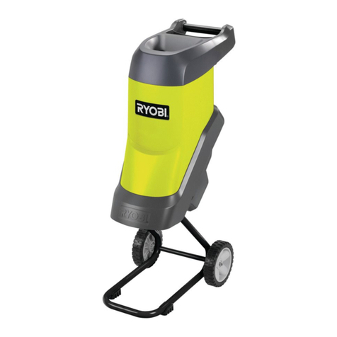
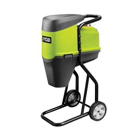
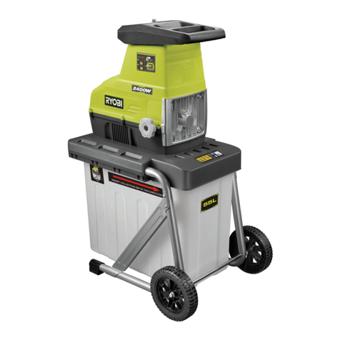
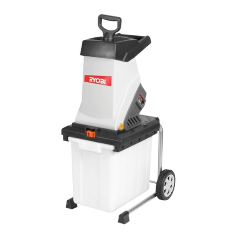
Ryobi RGS1500R Operation manual

RGS1500R
OWNER'S OPERATING MANUAL
ELECTRIC GARDEN SHREDDER
Your garden shredder has been engineered and manufactured to our high standard for dependability, ease of operation, and operator
safety. Properly cared for, it will give you years of rugged, trouble-free performance.
WARNING: To reduce the risk of injury, the user must read and understand the operator’s manual before using this product.
Thank you for your purchase. SAVE THIS MANUAL FOR FUTURE REFERENCE

1
TABLE OF CONTENTS
INTRODUCTION
● Introduction
● Product Description
● General Safety Rules
● Specic Safety Rules
● Specications
● Assembly
● Operation
● Maintenance & Troubleshooting
● Warranty
● Parts Ordering/Service
Page 1
Page 2
Page 6
Page 6
Page 7
Page 7
Page 7
Page 8
Page 10
Page 10
This product has many features for making its use more pleasant and enjoyable. Safety, performance,
and dependability have been given top priority in the design of this product making it easy to maintain and
operate.

DESCRIPTION
2
PRODUCT DESCRIPTION
1. Top hopper
2. Handle
3. Handle securing knobs
4. Wheels
5. Debris ejection chute
6. Top hopper securing
knobs
7. Side chute (see gure
12).
12
3
4
5
6

DESCRIPTION
Fig. 1 Fig. 2
Fig. 3 Fig. 4
Fig. 5 Fig. 6
3
Assemble wheels
Hub cap
Screw
Handle
shaft
Knob
Safety switch
PRODUCT DESCRIPTION
Plastic top hopper
Handle bar

Fig. 7 Fig. 8
Fig. 9 Fig. 10
Fig. 11 Fig. 12
4
ON/OFF switch
Overload protection
switch
Collection device is for illustration purposes
only and is not supplied
Spaner
Wedge
Center bolt
Scraping plate
Center bolt
Spring washer
Side chute
PRODUCT DESCRIPTION

Fig. 13
5
Allen key
PRODUCT DESCRIPTION

6
GENERAL SAFETY RULES
SPECIFIC SAFETY RULES
WARNING
This appliance complies with the
compulsory safety regulations for electric
equipment. However, improper use can
be harmful to people and property. Please
read these operating instructions carefully
and completely before switching the
appliance on. Save these instructions.
Refer to them frequently and use them to
instruct others who may use this product.
If you loan someone this tool, loan them
these instructions also.
WARNING
The appliance is not intended for use by
young children or infirm persons unless
they have been adequately supervised by
a responsible person to ensure that they
can use the appliance safely.
Young children should be supervised
to ensure that they do not play with the
appliance.
WARNING
When using this garden shredder basic
safety precautions, including the following,
should be followed to reduce the risk of re,
electric shock and personal injury. Read all
of these safety instructions carefully before
operating this garden shredder. Make sure
that you are familiar with the controls and
the proper and safe use of the garden
shredder.
■This appliance is not intended for use by
persons (including children) with reduced
physical, sensory or mental capabilities, or lack
of experience and knowledge, unless they have
been given supervision or instruction concerning
use of the appliance by a person responsible for
their safety.
TRAINING
■Become familiar with this user guide before
attempting to operate this shredder.
■Never allow children or people unfamiliar with
these instructions to use the garden shredder.
Local regulations may restrict the age of the
operator.
■The operator or user of this garden shredder is
responsible for accidents or hazards occurring to
other people or their property.
PREPARATION
■ Do not allow children to operate this equipment.
■Do not operate this equipment in the vicinity of
bystanders.
■Wear ear protection and safety glasses at all
times while operating the machine.
■ Avoid wearing clothing that is loose tting or that
has hanging cords or ties.
■Only operate the machine in open space (e.g.
not close to a wall or a fixed object) and on a
rm, level surface.
■Do not operate the machine on a paved or
gravel surface where ejected material could
cause injury.
■It is recommended that the shredder should be
used with a Residual Current Device (RCD) with
a tripping current of no more than 30mA.
■Before starting the machine, check that all
screws, nuts, bolts, and other fasteners are
properly secured and that guards and screens
are in place. Replace damaged or unreadable
labels.
■ Do not use this machine in wet, damp or raining
conditions.
OPERATION
■Before starting the machine, look into the feeding
chamber to make certain that it is empty.
■Keep your face and body away from the feed
intake opening.
■Do not allow hands or any other part of the
body or clothing inside the feeding chamber,
discharge chute, or near any moving part.
■Keep proper balance and footing all times. Do
not overreach. Never stand at a higher level than
the base of the machine when feeding material
into it.
■Always stand clear of the discharge zone when
operating this machine.
■When feeding material into the machine be
extremely careful that pieces of metal, rocks,
bottles, cans or other foreign objects are not
included.
■If the cutting mechanism strikes any foreign
objects or if the machine should start making
any unusual noise or vibration, shut off the
power source and allow the machine to stop.
Disconnect from supply and take the following
steps:
● Inspect for damage.
●Check and tighten any loose parts.
●Have any damaged parts replaced or repaired
with parts having equivalent specications.
7
SPECIFIC SAFETY RULES
OPERATION
ASSEMBLY
SPECIFICATIONS
ASSEMBLE FRAME & WHEELS
■ Align the holes in the wheels to the holes in the
axle section of the frame and secure tightly with
the bolts, spring washers and nuts provided as
shown in Fig. 1.
■ Afx the hub caps to the wheels. (Fig. 2)
TOP HOPPER
■Place the Top Hopper onto the metal feed tube
and align the screw holes. Secure the hopper to
the metal body using the screws provided. (Fig.
3)
HANDLE
■Insert the handle bar into the handle shafts
located at the rear of the machine. Align the
holes in the handle bar to the holes in the handle
shafts and secure with the 2 knobs as shown in
Fig. 4 & 5.
SAFTEY SWITCH
■The safety switch that is located on the cutter
base is activated when the metal Top Hopper
assembly is removed to help prevent accidental
starting. The safety switch does not require
assembly and if needed, should only be serviced
by an authorised Ryobi service centre Fig. 6
Read and understand the safety instructions
in this owner’s manual before using your
SHREDDER.
■Connect the machine to a suitable power outlet.
To start the machine, place the On/Off switch
located at the rear of the motor to “ON” position.
Fig. 7. To stop the machine, switch to the “OFF”
position.
ATTACHING MULCH BAG or COLLECTION
DEVICE
■You may place a heavy duty garbage bag or
Voltage
Power input
No load speed
Max. branch size
Sound level under load
no load
V-Blade spare part number
Marblade spare part numbe
Blade screw spare part number
Net weight
240V ~50Hz
1500W
2850 min-1
Ø35 mm
75db
105db
RGS1500R-27
RGS1500R-24
RGS1500R-25
29 kg
■Do not allow processed material to build up in
the discharge zone; this may prevent proper
discharge and can result in kickback of material
through the feed intake opening.
■If the machine becomes clogged, shut off the
power source and disconnect from supply
before clearing debris. Keep the power source
clear of debris and other accumulations to
prevent damage to the power source or possible
fire. Remember that operating the starting
mechanism on engine powered machines will
still cause the cutting means to move.
■Keep all guards and deflectors in place and in
good working condition.
■Do not transport the machine whilst connected
to a live power source.
■Always switch the shredder off and disconnect
from the power source whenever you leave the
work area.
■ Do not tilt the machine whilst the unit is running.
MAINTENANCE AND STORAGE
■When the machine is stopped for servicing,
inspection, storage, or to change an accessory,
disconnect the power source, make sure that all
moving parts have come to a complete stop and,
where a key is tted remove the key. Allow the
machine to cool before making any inspections,
adjustments, etc.
■The unit is tted with an interlock feature which
will disable the shredder from operation when
the metal housing is removed. When servicing
the cutting means be sure to disconnect the
power supply as a secondary precaution. Always
wear protective equipment when servicing
blades, as the sharp edges are capable of
inicting serious injury.
■Turn the shredder off and wait for all moving
parts to stop before clearing the clippings or
attaching or removing a collection device from
the front of the debris chute.
■Cord replacement should only be carried out by
an authorised person or by a Ryobi authorised
service centre.

8
WARNING
If ejection chute becomes clogged or
cutting blades become jammed, under no
circumstances should you place your hands
in the ejection chute to try to clear the
obstruction as this will lead to serious injury.
V-CUTTER MAINTENANCE
■Switch the machine off and disconnect the power
cord ensuring all moving parts are completely
stopped.
■Wear gloves when attempting any maintenance
to the cutting blades.
■If blades require replacing, ensure you use
genuine Ryobi parts.
DISASSEMBLY
■Unscrew and remove the handle and the 3
Top Hopper assembly knobs. Remove the Top
Hopper assembly by lifting and slightly tilting
forward.
■Rotate the cutter base counterclockwise and
place a suitable wedge between the cutter base
scrapping plates to stop the cutting base from
rotating. Fig. 9
■Remove the center bolt by turning it
counterclockwise using a wrench.
■Remove the square washer, square bushing,
V-cutting blades and V-cutter base.
SHREDDING BLADES MAINTENANCE
■To inspect or replace the double sided shredding
blades there is no need to remove the V-cutter
or cutting base. To remove simply undo the
countersunk screws with the hex wrench
provided with the machine and turn them 180°.
These blades are double ground and can be
used on both sides. When dull on both sides
replace with new blades and make sure they are
screwed in tightly.
ASSEMBLY
■This is carried out in the reverse order to that of
the disassembly but with careful inspection of all
components.
■Ensure that the cutter base is assembled with
the scraping plates facing down towards the
motor and that the spring washer is situated
under the head of the center hold down bolt. Fig.
10
■Before replacing the top cover assembly, ensure
that the V-cutter is positioned as shown in Fig.
11. This will ensure easier fitment of the metal
Top Hopper housing.
■Replace the metal Top Hopper assembly by
slightly tilting it forward, and hooking it under the
metal tongue on the cutter base plate. Secure
with the three Top Hopper assembly knobs.
Then ret the handle.
CLEANING
■After use, always wipe clean the outside of the
machine to remove any build up of material with
a damp cloth.
■ During normal operating conditions the shredder
should clear out all materials in the cutting
chamber. If the cutting chamber becomes
clogged or requires cleaning turn the machine
off, disconnect from any power source and
refer to the jammed and blade maintenance
instructions.
WARNING
Take extreme care not to come in contact
with cutting blades. Assemble the Top
Hopper in reverse order stated above.
JAMMING
If blades become jammed, switch off the machine
and disconnect the power cord from the power
source. Always wear gloves when attempting
maintenance of the cutting chamber. Unscrew and
remove the handle and the 3 Top Hopper assembly
knobs. Remove the Top Hopper assembly by lifting
and slightly tilting forward. Carefully remove the
obstruction from the cutting chamber.
OPERATION
collection device (not supplied) to the shredder
discharge chute (Fig.8). Always turn the
shredder off and wait for all moving parts to stop
before attaching or removing a collection device
from the front of the debris chute.
MAINTENANCE & TROUBLESHOOTING
Your SHREDDER has been designed for a low
level of maintenance, involving routine cleaning
and inspection. The motor of the machine is
maintenance free and requires no attention. For
best results the blades must be kept sharp at all
times. The blades have dramatically less cutting
power when dull. The machine will tear rather than
cut when the blades are dull. When this occurs
rotate the double sided blades or replace the
blades immediately.
WARNING
Before attempting any maintenance, switch
the machine off and disconnect the power
cord from power source.

9
MOTOR JAMMING
■If the motor stalls and stops due to overloading
or other cause, turn off the power switch and
disconnect the shredder from power source. Use
the provided allen key to turn the motor shaft
through the hole on the bottom of the motor
house. This should free up the movement of the
cutting disc (Fig.13).
■ Once there is free movement in the cutting disc,
remove the allen key and reconnect the machine
to the power source.
■If the shredder remains blocked, please follow
the instructions below.
OVERLOAD PROTECTION AND MOTOR
JAMMING
■If the motor stalls and stops due to overloading
or other cause, the overload protective device
(circuit breaker) will engage and cut power to the
motor. If this happens turn off the power switch
and disconnect the shredder from power source.
MAINTENANCE & TROUBLESHOOTING
WARNING
Do not under any circumstances place
hands inside the feeding chutes while the
machine is in operation. Force feeding of
debris is not necessary due to the natural
suction of the machine.
TOP HOPPER – FRONT CHUTE
■The sloping chute of the Top Hopper is designed
to accept leaves and small garden clippings.
Shredding and mulching is achieved by natural
suction of the debris through the blade chamber.
Do not overload and do not feed wet, soggy
material into the machine as this may clog the
blade chamber and the discharge chute.
■If a finer mulch is required than is initially
achieved, re-feed the mulch through again until
the desired result is obtained.
DO NOT FEED SOLID BRANCHES THOUGH
THE TOP HOPPER CHUTE.
SIDE CHUTE
■The chute located at the rear of the machine
is specially designed to accept solid garden
clippings and larger branches.
IMPORTANT:
When feeding long, large diameter material, control
the rate of feed by pulling back on the material so
as not to stall or overload the motor.
■Unscrew and remove the handle and the 3
Top Hopper assembly knobs. Remove the Top
Hopper assembly by lifting and slightly tilting
forward. Carefully remove the obstructions from
the cutting chamber.
■ Make sure there is free movement in the cutting
disc before reinstalling the metal hopper.
■Before replacing the top cover assembly, ensure
that the V-cutter is positioned as shown in Fig.
11. This will ensure easier fitment of the metal
Top Hopper housing.
■Replace the metal Top Hopper assembly by
slightly tilting it forward, and hooking it under the
metal tongue on the cutter base plate. Secure
with the three Top Hopper assembly knobs.
Then ret the handle.
■Press in and release the reset button (circuit
breaker, Fig. 7) and reconnect the machine to
the power source.

10
LIMITED WARRANTY
TTI warrants this outdoor product to be free of defects in material and workmanship for 24 months from the
date of purchase by the original purchaser, subject to the limitations below. Please keep your invoice as proof
of date of purchase.
This warranty is only applicable where the product is used for personal and non-commercial purposes.
This warranty does not cover damage or liability caused by / due to misuse, abuse, accidental or intentional
acts by user, improper handling, unreasonable use, negligence, failure by end user to follow operating
Please see your local dealer for list of authorized service centre’s in your area.
This warranty does not cover belts, brushes, bags, bulbs, blades, or any part which ordinary wear and tear
results in required replacement during warranty period. This warranty does not cover transportation costor
consumable items such as fuses and batteries.
have been defaced, altered or removed or if product is not purchased from an authorized reseller or if product
is sold AS IS and / or WITH ALL FAULTS.
Where permitted, the provisions of this limited warranty are in lieu of any other written warranty, whether
express or implied, written or oral, including any warranty of MERCHANTABILITY OR FITNESS FOR A
PARTICULAR PURPOSE. IN NO EVENT SHALL WE BE LIABLE FOR SPECIAL, INCIDENTAL, CONSEQUENTIAL OR
INCIDENTAL DAMAGES. OUR MAXIMUM LIABILITY SHALL NOT EXCEED THE ACTUAL PURCHASE PRICE PAID BY
YOU FOR THE PRODUCT.
This warranty is applicable only in Australia, and New Zealand. Outside
these areas, please contact your authorized Ryobi dealer to determine
if another warranty applies.
TECHTRONIC INDUSTRIES AUSTRALIA PTY LIMITED.
TECHTRONIC INDUSTRIES (NZ) LIMITED.
SERVICE
For parts or service, contact your nearest Ryobi authorised service dealer. Be sure to provide all relevant information when you
call or visit. For the location of the authorised service dealer nearest you, please call 1300 361 505 (Aust) or 9573 0230 (NZ)
REPAIR PARTS
The model number of this tool is found on a plate or label attached to the housing.
Please record the serial number in the space provided below.
MODEL NUMBER ___________________ SERIAL NUMBER ___________________
DONCASTER VICTORIA AUSTRALIA
Tel: (03) 9840 3200 1300 361 505 Fax: 1800 807 993
AUCKLAND NEW ZEALAND
Tel: + 64 (0) 9 573 0230 Free Call: +64 0800 279 624 Fax: + 64 (0) 9 573 023
Table of contents
Other Ryobi Paper Shredder manuals

Ryobi
Ryobi RSH2445S User manual

Ryobi
Ryobi RGS-2540 Operation manual

Ryobi
Ryobi RSH2400RG User manual

Ryobi
Ryobi RSH3045U User manual

Ryobi
Ryobi RSH2545B User manual

Ryobi
Ryobi RSH2845T User manual

Ryobi
Ryobi RSH2400R User manual

Ryobi
Ryobi GGS-3000 Operation manual

Ryobi
Ryobi RSH2400R User manual

Ryobi
Ryobi RSH2845T User manual