Ryobi EHP-371 User guide

cod.90039 - MD
EHP-371

2
Contents Page
Introduction............. 7
Safetyrules….......... 7
Generalrules............ 8
Installation………… 8
Use......................... 9
Maintenance ............ 9
Troubleshooting...... 10
Electrical
diagrams ............... 55
Sommaire Page
Présentation........... 11
Règlesdesécurité... 11
Recommandations
générales............... 12
Installation............. 12
Utilisation .............. 13
Entretien................ 13
Problèmes et
remèdes ................ 15
Schémas
électriques............. 55
Inhaltsverzeichnis
Seite
Vorstellung ............ 16
Sicherheits-
vorschriften............ 16
Allgemeine
Vorschriften ........... 17
Installation............. 18
Gebrauch............... 18
Instandhaltung ....... 19
Störungen und
Behebung .............. 20
Schaltpläne............ 55
Indice Pagina
Presentazione......... 21
Prescrizioni di
sicurezza................ 21
Prescrizioni
generali ................. 22
Installazione........... 22
Uso....................... 23
Manutenzione......... 23
Inconvenienti e
rimedi.................... 24
Schemielettrici....... 55
Índice Página
Presentación.......... 25
Instrucciones de
seguridad............... 25
Instrucciones
generales............... 26
Instalación............. 26
Uso....................... 27
Mantenimiento ....... 28
Problemas y
soluciones ............. 29
Esquemas
eléctricos............... 55
Índice Página
Apresentação ......... 30
Normas de
segurança.............. 30
Normasgerais........ 31
Instalação.............. 31
Uso....................... 32
Manutenção........... 32
Problemas e
soluções................ 33
Esquemas
elétricos................. 55
Inhoud Pagina
Inleiding ................ 34
Veiligheids-
voorschriften.......... 34
Algemene
voorschriften.......... 35
Installatie............... 36
Gebruik.................. 36
Onderhoud............. 37
Storingen en
oplossingen ........... 38
Elektrische
schema’s ............... 55
Indhold Side
Indledning.............. 39
Sikkerhedsregler..... 39
Generelleregler ...... 40
Installation............. 40
Anvendelse ............ 41
Vedligeholdelse ...... 41
Problemer og
afhjælpning............ 42
Elektriske
diagrammer ........... 55
Innehåll Sida
Inledning............43
Säkerhetsbestäm-
melser.................43
Allmänna
anvisningar........44
Installering.........44
Användning .......45
Underhåll............45
Störningar och
åtgärder..............46
Elschema ...........55
Sisältö Sivu
Johdanto ............... 47
Turvamääräykset..... 47
Yleisetohjeet.......... 48
Asennus ................ 48
Käyttö.................... 49
Kunnossapito......... 49
Häiriöt ja niiden
korjaukset.............. 50
Sähkökaavio........... 55

3
•Weight of cleaner
without accessories:
15.4 lb.
•Gun recoil at the
maximum pressure: 9,5
N.Acoustic pressure
level measured in
conformity with EN
60704-1 and ISO 3744.
•Poids sans accessoires
7 kg.
•Force de répulsion sur
le pistolet à la pression
maximale de 9,5 N. Le
niveau de pression
acoustique est relevé
conformément aux
normes EN 60704-1 et
ISO 3744.
•Gewicht ohne Zubehör:
7 kg.
•Rückstoßkraft auf die
Pistole bei Höchstdruck
- 9,5 N.
Der Schalldruckpegel
wurde nach den Normen
EN 60704-1 und ISO
3744 gemessen.
•Peso senza accessori
7 kg.
•Forza repulsiva sulla
pistola alla pressione
massima 9,5 N.
Il livello di pressione
acustica è rilevato
secondo le norme EN
60704-1 e ISO 3744.
•La hidrolimpiadora pesa
7 kg sin los accesorios.
•La fuerza de repulsión
en la pistola con la
máxima presión es de
9,5 N. La medición del
nivel de presión acústica
se efectúa según las
normas EN 60704-1 e
ISO 3744.
•Peso sem acessórios
7 kg.
•Força repulsiva na
pistola na pressão
máxima: 9,5 N.
O levantamento do nível
de pressão acústica é
feito segundo as normas
EN 60704-1 e ISO 3744.
• Gewicht van de
hogedrukreiniger zonder
accessoires 7 kg.
•Terugslag van het pistool
bij de maximale druk:
9,5 N. Het
geluidsdrukniveau is
gemeten volgens de EN
60704-1 en ISO 3744
normen.
•Højtryksrenserens vægt
uden tilbehør: 7 kg.
•Pistolens tilbagestød
ved maksimalt tryk 9,5
N. Lydtryksniveauet er
blevet målt jf. EN 60704-
1 og ISO 3744
standarden.
• Högtryckstvättens vikt utan
tillbehör är ca. 7 kg.
•Tvättpistolens rekylkraft är
vid max. tryck: 9,5 N.
Ljudtrycksnivån har
uppmätts enligt
standarderna EN 60704-1
och ISO 3744.
•Pesurin paino ilman
tarvikkeita on n. 7 kg.
•Pesupistoolin
työntövoima on maks.
paineella £ 9,5 N.
Äänen painetaso on
mitattu standardien EN
60704-1 ja ISO 3744
mukaan.

4
em
p
i
dg
f
fig. 3/A
fig. 4/B
fig. 4/C
fig. 3/B
fig. 4/A
fig. 4/D
a
bh
c

55
fig. 5/A
fig. 5/E
fig. 6/B
fig. 6/D
fig. 5/D
fig. 6/C
M
fig. 5/B fig.
5/C
fig. 6/A

6
MODEL
MODEL
TYPE
TIPO
PUISSANCE (w)
POWER (w)
LEISTUNG (w)
POTENCIA (w)
PRESSION (bar)
PRESSURE (bar)
DRUCK (bar)
PRESION (bar)
DEBIT (l/h)
OUTPUT (l/h)
LEITSTUNG (l/h)
CAUDAL (l/h)
EHP-371 1300 100 (Max) 375

55
P1
P2
5
Sr
nM
1 ~
b
a
C
N
L1
2
n b a r
BLACK WHITE BLUE RED
NOIR BLANC BLEU ROUGE
SCHWARZ WEISS BLAU ROT
NERO BIANCO AZZURRO ROSSO
NEGRO BLANCO AZUL ROJO
PRETO BRANCO AZUL VERMELHO
ZWART WIT BLAUW ROOD
SORT HVID BLÅ RØD
SVART VIT BLÅ RÖD
MUSTA VALKOINEN SININEN PUNAINEN
The characteristics and descriptions given
are not binding. - Les données, les
descriptions et les illustrations de cette notice
n’engagent pas le fabricant. - Angaben,
Beschreibungen, und Illustrationen sind nicht
verbindlich. - Dati, descrizioni ed illustrazioni
sono forniti a titolo indicativo e non
impegnativo. - Los datos, las descripciones
y las ilustraciones se suministran a título
indicativo y no comprometen al fabricante.
- As características e ilustrações não
vinculam o fabricante. - Gegevens,
beschrijvingen en illustraties dienen ter
oriëntatie en zijn niet bindend. - Alle de
leverede data, beskrivelser og tegninger er
kun vejledende. - Informationer och bilder
utan förbindelse - Tiedot ja kuvat
sitoumuksetta.
1/f
4
1
5
S
n
M
1 ~
b
a
C
N
L1 r
2T
230V/50Hz
220V/60Hz 115V/60Hz
100V/50-60Hz
230V/50Hz
220V/60Hz
P1
P2
3
S
n
M
1 ~
b
a
C
N
L1
Vers.TSS
r
6
S1
m
b
NC
NAC
P=O
4
1
5
S
n
M
1 ~
b
a
C
N
L1
Vers.TSS
r
2T
S1
m
b
NC
NAC
P=O
115V/60Hz
100V/50-60Hz

2.1.13 DO NOT leave the cleaner
unattended. ACCIDENT HAZARD
2.1.14 DO NOT move the cleaner by
pulling on the electrical cable. SHORT
CIRCUIT HAZARD
2.2 SAFETY "MUSTS"
2.2.1 All electrical conductors MUST BE
PROTECTED against the water jet.
SHORT CIRCUIT HAZARD
2.2.2 The cleaner MUST ONLY BE
CONNECTED to a correctly
earthed power supply. ELECTRIC SHOCK HAZ-
ARD
• Use of a safety residual current circuit-
breaker (R.C.C.B.) will provide additional
protection for the operator (30 mA).
2.2.3 The high pressure
may cause materi-
als to bounce off surfaces at speed; there-
fore protective clothing and safety goggles
MUST BE WORN. INJURY HAZARD
2.2.4 Before doing work on the cleaner,
REMOVE the plug. ACCIDENTAL
START-UP HAZARD
2.2.5 Before pressing the trigger, GRIP
the gun firmly to counteract the
recoil. INJURY HAZARD
2.2.6 COMPLY WITH the requirements of
the local water supply company.
According to DIN 1988, power-jet cleaners
may only be connected to the mains drink-
ing water supply if a backflow preventer
valve with drain facility is installed in the
supply hose. CONTAMINATION HAZARD
2.2.7 Maintenance and/or repair of electri-
cal components MUST be carried
out by qualified staff. ACCIDENT HAZARD
2.2.8 DISCHARGE residual pressure
before disconnecting the cleaner
hose. INJURY HAZARD
2.2.9 Before using the cleaner, CHECK
every time that the screws are fully
tightened and that there are no broken or
worn parts. ACCIDENT HAZARD
2.2.10 Only USE detergents which
will not corrode the coating
materials of the high pressure
hose/electrical cable. EXPLO-
SION AND ELECTRIC SHOCK HAZARD
2.2.11 ENSURE that all people or
animals keep a minimum dis-
tance of 16 yd. (15m) away. INJURY HAZARD
KEY
1INTRODUCTION
1.1 The high pressure power-jet cleaner you
have purchased is a technologically
advanced product designed by one of the
leading European manufacturers of high
pressure pumps. To obtain the best per-
formance from your unit, read this booklet
carefully and follow the instructions each
time you use the cleaner. We congratulate
you on your choice and wish you success-
ful operation.
2SAFETY RULES
2.1 SAFETY "MUST NOTS"
2.1.1 DO NOT use the cleaner with
inflammable or toxic liquids, or
any products which are not
compatible with the correct
operation of the cleaner. EXPLOSION OR POI-
SONING HAZARD
2.1.2 DO NOT direct the water jet
towards people or animals.
INJURY HAZARD
2.1.3 DO NOT direct the water jet
towards the unit itself, electri-
cal parts or towards other electrical equip-
ment. ELECTRIC SHOCK HAZARD
2.1.4 DO NOT use the cleaner outdoors
in case of rain. SHORT CIRCUIT HAZARD
2.1.5 DO NOT allow children or incompe-
tent persons to use the cleaner.
INJURY HAZARD
2.1.6 DO NOT touch the plug and/or
socket with wet hands. ELEC-
TRIC SHOCK HAZARD
2.1.7 DO NOT use the cleaner if the
electrical cable is damaged.
ELECTRIC SHOCK AND SHORT CIRCUIT HAZARD
2.1.8 DO NOT use the cleaner if the
high pressure hose is dam-
aged. EXPLOSION HAZARD
2.1.9 DO NOT jam the trigger in the oper-
ating position. ACCIDENT HAZARD
2.1.10 Check that the data plates are af-
fixed to the cleaner, if not, inform
your dealer. Cleaners without plates must
NOT be used as they are unidentifiable
and potentially dangerous. ACCIDENT HAZ-
ARD
2.1.11 DO NOT tamper with or with or
alter the calibration of the safe-
ty valve. EXPLOSION HAZARD
2.1.12 DO NOT alter the original diameter
of the spray head nozzle. HAZ-
ARDOUS ALTERATION OF OPERATING PERFOR-
MANCE
7
English
interno1e 4-02-2003 18:43 Pagina 7

must be disposed of in compliance with
the regulations in force in the country of
installation.
3.1.11 Use the cleaner only with accessories and
replacement parts authorised by the man-
ufacturer. The use of original accessories
and replacement parts will ensure safe,
trouble-free operation.
3.1.12 The cleaner must be used standing on
a secure, stable surface, positioned as
shown. FIG.3A
3.2 INTENDED USE
3.2.1 The cleaner is intended only for the clean-
ing of vehicles, machines, boats, build-
ings, etc., by the removal of stubborn dirt
using clean water and chemical deter-
gents.
3.2.2 When using chemical detergents, only
use biodegradable types.
We recommend HOBBY - FOAM deter-
gent (# 3206).
3.2.3 Only clean vehicle engines in areas in
which suitable oil traps are installed.
3.3 SAFETY VALVE
3.3.1 The safety valve also functions as a pres-
sure limiting valve. When the gun trigger is
released, the safety valve opens and the
water recirculates through the pump inlet.
4INSTALLATION
4.1 Fit the lance into the gun by rotat-
ing and pushing until the two
parts are completely locked. FIG.4A
4.2 Connect the gun to the high pressure
hose. FIG.4B
4.3 Connect the high pressure hose to the
water (OUTLET) on the cleaner. FIG.4C
4.4 Connect the water supply hose FIG.4D
(not supplied) to the water (INLET) of the
cleaner. The supply hose must have an
internal diameter of at least 13 mm (1/2
in.) and must be reinforced. The water
supply must be at least equal to the clean-
er delivery capacity.
The intake water tempera-
ture must NOT exceed 50°C
(122°F). The water supply pressure
must NOT exceed 10 bar (145 psi).
4.4.1 CAUTION! The cleaner must only
be used with clean water; use of
unfiltered water or corrosive chemicals
will damage the cleaner.
4.5 Turn the motor switch to the "0" position.
4.6 Check that the electrical supply voltage
and frequency (Volts/Hz) correspond to
those specified on the cleaner data plate.
FIG.3B
If the power supply is correct, you may
a-Water outlet (OULET)
b-Water inlet with filter (INLET)
c-High pressure rotating nozzle kit
(optional accessory)
d-Adjustable spray nozzle
e-Use • Maintenance handbook
f-Power supply cable with plug
g-Lance
h-Gun with safety catch
i-High pressure hose
m-Nozzle cleaning tool
n-Motor switch
p-Adjustable foam unit
3GENERAL RULES
3.1.1 The USE and MAINTENANCE manual
constitutes an essential part of the cleaner
equipment and should be kept in a safe
place for future reference. If you sell the
cleaner, the manual should be handed on
to the new owner.
3.1.2 Before starting the cleaner, make sure that
it is receiving water correctly. Operating
the cleaner without water could damage
the seals.
3.1.3 Do not disconnect the plug by pulling on
the electrical cable.
3.1.4 If you are too far from the object you wish
to clean, do not move the cleaner nearer
by pulling on the high pressure hose; use
the handle provided.
3.1.5 In versions not equipped with TSS
device, do not operate the cleaner for
more than 1-2 minutes with the gun
closed as this could damage the seals.
3.1.6 Protect the cleaner from freezing during
the winter.
3.1.7 Do not obstruct the ventilation grilles dur-
ing operation.
3.1.8 The cross-section of any exten-
sion cables used must be propor-
tional to their length, i.e. the longer the
extension cable, the greater the cross-
section; cables with a protection level
of "IPX5" must be used. See table a for
details.
Table a.
3.1.9 Position the cleaner AS NEAR AS POS-
SIBLE to the water supply.
3.1.10 The packaging is easily recyclable, and
8English
Voltage Extension Extension
Volts cable cable
up to 25 m up to 50 m
220 - 230 section section
MOTOR 240 3x1.5 mm23x2.5 mm2
100 - 115 section section
120 3x2.5 mm23x4 mm2
interno1e 4-02-2003 18:44 Pagina 8

ZLE (Where fitted)
5.6.1 For increased washing power, use the
rotary nozzle kit as follows:
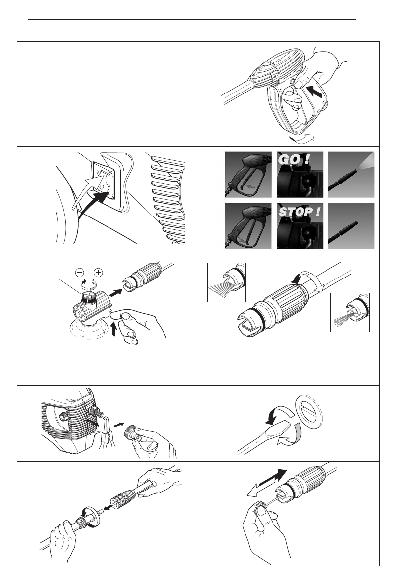
5.6.2 Turn off the high pressure cleaner
5.6.3 Unscrew the adjustable head and fit the
rotary nozzle onto the lance.
5.6.4 Turn the high pressure cleaner back on.
5.7 RECOMMENDED CLEANING PROCE-
DURE
5.7.1 Dissolve dirt by applying detergent with
the fan jet to the dry surface.
On vertical surfaces, work from the bottom
upwards. Leave the detergent to act for 1
to 2 minutes, but do not allow to dry out.
Apply the high pressure jet, keeping the
nozzle at least 30 cm (10 in.) from the sur-
face, working from the bottom upwards.
Avoid allowing the rinsing water to run on
to unwashed surfaces.
5.8 STORAGE
5.8.1 Switch off the cleaner.
5.8.2 Turn off the water supply tap.
5.8.3 Discharge residual pressure by pressing
the trigger until no more water comes out
of the adjustable nozzle.
5.8.4 Engage the gun safety catch.
5.8.5 Remove the plug from the socket.
5.8.6 Operate the cleaner with non-
corrosive/non-toxic antifreeze before stor-
ing for the winter.
6MAINTENANCE
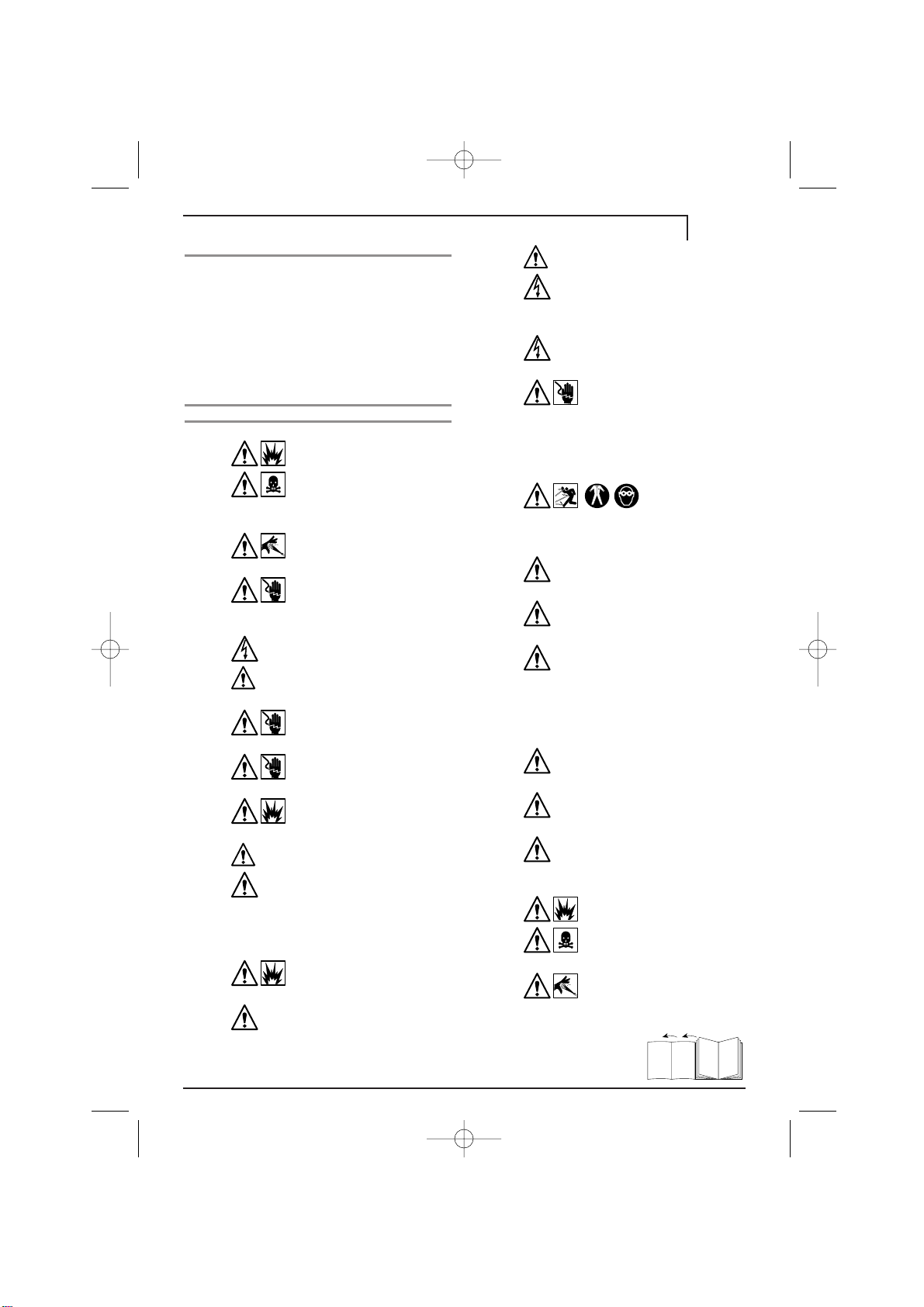
6.1 CAUTION! Before working on the
cleaner, disconnect the plug from
the power supply socket.
6.2 To ensure good performance, check and
clean the suction and detergent filters after
every 50 hours of operation. FIG.6A
6.3 Long periods of disuse may lead
to the formation of lime scale
deposits. Working through the hole on
the rear, RELEASE the motor using a
screwdriver (for models with this fea-
ture). FIG.6B
Then remove the screwdriver and pro-
ceed with the restart operations.
6.4 Clean the nozzle with the tool provided.
Remove the lance from the gun (FIG.6C),
remove any dirt from the nozzle hole
(FIG.6D) and rinse.
now plug in the cleaner.
The electric supply connection shall be
made by a qualified electrician and comply
with IEC 364. It is recommended that the
electric supply to this appliance should
include either a residual current device that
will interrupt the supply if the leakage cur-
rent to earth exceeds 30 mA for 30 ms or a
device which will prove the earth circuit.
CAUTION! The machine may
cause electrical disturbances
when starting.
4.6.1 If the motor stops and fails to restart, wait
2-3 minutes before restarting. THERMAL
CUTOUT TRIPPED
5USE
5.1 Turn on the water supply tap FULLY.
5.2 Release the safety catch FIG.5A, then
press the trigger for a few seconds to
allow air to escape and to discharge
residual pressure in the pipes.
5.3 Keeping the trigger pressed, push the
switch to start the motor. FIG.5B
5.3.1 When re-starting the motor, always
keep the trigger pressed.
TSS Models: In TSS models, (FIG. 5C) with auto-
matic delivery flow cut-off:
-when the trigger is released, the dynamic
pressure automatically cuts out the motor.
-When the trigger is pressed the pressure
drop automatically starts the motor and
the pressure is restored with a very slight
delay.
-For correct operation of the TSS, once the
trigger has been released it must not be
pressed again for at least 4-5 seconds.
For correct use of the TSS model cleaner,
do not leave the unit in automatic cut-off
status for more than 15 min.
5.4 USING DETERGENT
5.4.1 Fill the foam unit tank with detergent
(capacity about 0.5 lt.).
5.4.2 5.4.1 Set the adjustable head in the “FAN
JET” position, then fit the foam unit on the
head and fix it in position. FIG. 5D
5.4.3 Now distribute the detergent drawn in and
mixed with water.
5.5 CORRECT USE OF STANDARD
ACCESSORIES
5.5.1 The cleaner is equipped with a nozzle for
adjustment of the jet from concentrated to
fan. FIG. 5E
5.5.2 It is also equipped with the foam unit for
detergent distribution, with adjustment of
the quantity of detergent using the knob
M. FIG. 5D
5.6 CORRECT USE OF THE ROTARY NOZ-
9
English
interno1e 4-02-2003 18:44 Pagina 9

Switch off the cleaner and operate the gun until a steady
flow of water is obtained. Then switch cleaner back on
Nozzle worn
Supply voltage below required minimum
Voltage loss due to use of extension cable of
inadequate cross-section or excessive length
High pressure system or pump hydraulic
circuit not watertight
POSSIBLE CAUSES
REMEDIES
TROUBLESHOOTING
PROBLEM
The pump does not operate at the prescribed pressure
Sudden changes in pump pressure
The motor buzzes but fails to start
Motor does not start
Water leakages
Excess noise
Oil leaks
For TSS MODELS ONLY: Motor starts even though the trigger is released
For TSS MODELS ONLY: No water when lever is operated (when supply hose is connected)
Power cable damaged
§ If the motor stops and fails to restart, wait-2-3 minutes before restarting (OVERLOAD CUTOUT TRIPPED). If this
fault occurs more than once, contact your service centre.
Water filter fouled
Water supply pressure low
Air being sucked into the system
Air in pump
Adjustable nozzle positioned wrongly
Water suction from external tank
Water temperature too high
Nozzle clogged
Worn seals
No electrical power
High pressure cleaner in disuse for long
time
Problems with TSS device
Replace nozzle
Clean filter
Turn on the water supply tap fully
Check that hose fittings are tight
Pull adjustable nozzle back (+)
Connect cleaner to mains water supply
Reduce temperature
Disconnect power supply, discharge pressure
and clean with tool provided
Have seals replaced by an authorised service
centre
Check that the plug is firmly in the socket and that
mains power is present. See also (§)
Check the voltage of the mains supply line
Consult instructions regarding extension cables
Release motor with a screwdriver, working through
rear hole
(for models with this feature)
(fig. 6B)
Contact nearest service centre
High pressure cleaner in disuse for long
time Contact nearest service centre
10 English
interno1e 4-02-2003 18:44 Pagina 10

11
Français
2.1.11 N’altérez jamais ni modifiez le
tarage de la soupape de régla-
ge.
DANGER D’EXPLOSION
2.1.12 Ne modifiez pas le diamètre d’origi-
ne du jet de la tête.
DANGER! LE FONC-
TIONNEMENT RISQUE D’ÊTRE COMPROMIS
2.1.13 Ne laissez jamais le nettoyeur sans
surveillance.
DANGER D’ACCIDENT
2.1.14 Ne déplacez jamais le nettoyeur en
le tirant par le câble électrique.
DAN-
GER DE COURT-CIRCUIT
2.2 AVERTISSEMENTS: A FAIRE
2.2.1 Toutes les parties conductrices de
courant DOIVENT ETRE PROTE-
GEES contre le jet d’eau.
DANGER DE COURT-
CIRCUIT
2.2.2 BRANCHEZ le nettoyeur
exclusivement sur une source
d’électricité mise à la terre.
DANGER DE CHOC
ELECTRIQUE
• Dans ce cas, le fonctionnement avec un
disjoncteur différentiel de sécurité offre
une protection personnelle supplémentai-
re (30 mA).
2.2.3 La haute pression
peut faire rebondir
les pièces; PORTEZ toujours des vête-
ments et des lunettes de protection.
DAN-
GER DE LESIONS
2.2.4 Avant d’exécuter toute opération
sur le nettoyeur, DEBRANCHEZ
l’appareil.
DANGER DE DEMARRAGE ACCIDENTEL
2.2.5 A cause du recul, SAISISSEZ BIEN
le pistolet lorsque vous tirez le
levier.
DANGER DE LESIONS
2.2.6 RESPECTEZ les règles de la société
des eaux potables de la région.
Suivant DIN 1988, il est possible de
connecter le nettoyeur directement au
réseau d’eau potable uniquement si la
tuyauterie d’alimentation comporte un dis-
positif anti-reflux avec vidange.
DANGER DE
POLLUTION
2.2.7 L’entretien et/ou la réparation des
composants électriques DOIVENT/
DOIT être effectué(s) par du personnel
qualifié.
DANGER D’ACCIDENT
2.2.8 RELACHEZ la pression résiduelle
avant de déconnecter le tube du
nettoyeur.
DANGER DE LESIONS
2.2.9 CONTROLEZ avant toute utilisation
et de temps à autre le serrage des
vis et le bon état des composants du net-
toyeur. Vérifiez s’il y a des pièces cassées
ou usagées.
DANGER D’ACCIDENT
1PRESENTATION
1.1 Le nettoyeur à haute pression que vous
venez d'acheter est un produit de très
haut niveau technologique réalisé par
l'une des entreprises européennes les
plus expertes en la fabrication de pompes
à haute pression. Pour obtenir des perfor-
mances optimales, veuillez lire et obser-
ver scrupuleusement les instructions que
nous avons formulées à chaque fois que
vous utiliserez cet appareil. Nous vous
félicitons de votre choix et vous souhai-
tons un bon travail.
2REGLES DE SECURITE
2.1 AVERTISSEMENTS: A NE PAS FAIRE
2.1.1 N'utilisez jamais le nettoyeur
avec des fluides inflam-
mables, toxiques ou dont les
caractéristiques ne
sont pas compatibles avec le fonctionn-
ment correct du nettoyeur.
DANGER D’EXPLO-
SION ET D’EMPOISONNEMENT
2.1.2 Ne dirigez jamais le jet d'eau
contre des personnes ou des
animaux.
DANGER DE LESIONS
2.1.3 Ne dirigez jamais le jet d'eau
contre le nettoyeur, les parties
électriques ou tout autre appareil élec-
trique.
DANGER DE CHOC ELECTRIQUE
2.1.4 N'utilisez jamais le nettoyeur en
plein air en cas de pluie.
DANGER DE
COURT-CIRCUIT
2.1.5 Ne laissez jamais la machine entre
les mains d'enfants ou de personnel
non formé.
DANGER D’ACCIDENT
2.1.6 Ne prenez jamais la fiche ou la
prise avec les mains
mouillées.
DANGER DE CHOC ELECTRIQUE
2.1.7 N’utilisez jamais le nettoyeur
si son câble électrique est
endommagé.
DANGER DE CHOC ELECTRIQUE ET
COURT-CIRCUIT
2.1.8 N’utilisez jamais le nettoyeur si
son tube à haute pression est
endommagé.
DANGER D’EXPLOSION
2.1.9 Ne bloquez pas le levier du pistolet
si l’appareil est en marche.
DANGER
D’ACCIDENT
2.1.10 Vérifiez la présence de la plaquette
des caractéristiques sur le net-
toyeur; le cas échéant, contactez immé-
diatement le revendeur. N’utilisez en
aucun cas un nettoyeur dont on ne
connaît pas les données pour éviter
d’éventuels accidents graves.
DANGER D’AC-
CIDENT
interno1e 4-02-2003 18:44 Pagina 11

3.1.8 La section des câbles de la ral-
longe doit être proportionnée à la
longueur (câble plus long = section
plus grande); enfin, n’utilisez que des
câbles avec un degré de protection
“IPX5”. Pour plus de détails, voir le
tableau a.
Tableau a.
3.1.9 Placez le nettoyeur, dans la mesure du
possible, APROXIMITE du réseau
hydrique d’approvisionnement.
3.1.10 Le matériau d’emballage est facilement recy-
clable et doit être écoulé conformément aux
normes en vigueur dans le pays d’utilisation.
3.1.11 Utilisez le nettoyeur exclusivement avec
les accessoires et les pièces de rechange
agréées par le client afin de garantir un
fonctionnement sans inconvénients et en
toute sécurité.
3.1.12 Le nettoyeur doit fonctionner posé sur
un plan sûr et stable, positionné
comme indiqué sur la FIG.3A.
3.2 UTILISATION
3.2.1 Pour le nettoyage de véhicules,
machines, embarcations, bâtiments, etc. Il
élimine les saletés les plus tenaces à
l’eau propre et avec des détergents chi-
miques.
3.2.2 Lors du lavage avec des produits chi-
miques, utilisez exclusivement des déter-
gents biodégradables.
Nous conseillons le détergent HOBBY -
FOAM (# 3206).
3.2.3 Les moteurs des véhicules ne peuvent
être lavés que dans des endroits équipés
de séparateur d’huile prévu à cet effet.
3.3 DISPOSITIF DE SECURITE
3.3.1 La soupape de surpression fait également
fonction de limiteur. En fermant le pistolet,
la soupape s’ouvre et l’eau recircule dans
l’aspiration de la pompe.
4INSTALLATION
4.1 Raccordez la lance au pistolet en
tournant et en poussant jusqu’au
blocage total des deux parties. FIG. 4A
4.2 Connectez le pistolet au flexible haute
pression. FIG. 4B
4.3 Connectez le flexible haute pression à la
sortie d’eau du nettoyeur. FIG. 4C
2.2.10 N’UTILISEZ QUE des déter-
gents compatibles avec les
matériaux de revêtement du
flexible haute pression/câble
électrique.
DANGER D’EXPLOSION ET DE CHOC
ELECTRIQUE
2.2.11 Les personnes ou les animaux
DOIVENT ETRE à la distance
minimale de 15 m.
DANGER DE LESIONS
LEGENDE
a-Sortie eau (SORTIE)
b-Entrée eau avec filtre (ENTREE)
c-Kit buse tournante (accessoire en
option)
d-Tête réglable
e-Notice d’utilisation et d’entretien
f-Câble électrique avec fiche
g-Lance
h-Pistolet avec sécurité
i-Flexible haute pression
m-Outil nettoyage tête
n-Interrupteur moteur
p-Dispositif moussant réglable
3RECOMMANDATIONS GENERALES
3.1.1 La notice USAGE ET ENTRETIEN doit
être considérée comme partie intégrante
du nettoyeur; conservez-la soigneuse-
ment pour toute consultation ultérieure.
En cas de revente du nettoyeur, n’oubliez
pas d’inclure cette notice.
3.1.2 Avant de mettre le nettoyeur en fonction,
assurez-vous qu’il est correctement ali-
menté par l’eau. En effet, toute utilisation
à sec endommagerait le système d’étan-
chéité.
3.1.3 Ne débranchez jamais l’appareil en le
tirant par le câble électrique.
3.1.4 Si vous êtes trop loin de ce que vous sou-
haitez laver, n’approchez jamais le net-
toyeur en le tirant par le tube à haute pres-
sion, mais déplacez-le à l’aide de la poi-
gnée prévue à cet effet.
3.1.5 Avec le pistolet fermé, dans les ver-
sions sans dispositif TSS, évitez de
faire fonctionner le nettoyeur pendant
plus de 1÷2 minutes pour ne pas
endommager le système d’étanchéité.
3.1.6 Protégez le nettoyeur contre le gel pen-
dant l’hiver.
3.1.7 Ne couvrez pas les grilles de ventilation
lors du fonctionnement.
12 Français
Tension Rallonge Rallonge
Volt jusqu'à 25 m jusqu'à 50 m
220 - 230 section section
MOTEUR 240 3x1,5 mm23x2,5 mm2
100 - 115 section section
120 3x2,5 mm23x4 mm2
interno1e 4-02-2003 18:44 Pagina 12

13
Français
démarre automatiquement le moteur et la
pression se reforme avec un petit retard.
-Pour le bon fonctionnement du TSS, les
opérations de fermeture et d’ouverture ne
doivent pas être effectuées dans un inter-
valle de temps inférieur à 4÷5 secondes.
Pour utiliser correctement le nettoyeur
TSS, ne le laissez pas en position d’arrêt
automatique pendant plus de 15 minutes.
5.4 UTILISATION DU DETERGENT
5.4.1 Remplissez le réservoir du dispositif
moussant avec du détergent (capacité
environ 0,5 Lt.).
5.4.2 Réglez la tête dans la position “JET EN
ÉVENTAIL”, introduisez et bloquez le dis-
positif moussant sur la tête. FIG. 5D
5.4.3 Répandez le détergent aspiré, mélangé
avec de l’eau.
5.5 Pour bien utiliser les accessoires standard
5.5.1 Le nettoyeur est équipé d’une tête qui per-
met le réglage du jet de la position concen-
trée à la position en éventail FIG. 5E
5.5.2 Le pistolet est également équipé du dis-
positif moussant pour la diffusion du
détergent avec possibilité de réglage de la
quantité de détergent à l’aide de la manet-
te M. FIG. 5D
5.6 UTILISATION CORRECTE DE LA BUSE
TOURNANTE
(pour les modèles qui en sont équipés)
5.6.1 Pour un lavage plus puissant, utilisez le kit
buse tournante comme suit:
5.6.2 Mettez le nettoyeur hors tension.
5.6.3 Enlevez la tête réglable et introduisez la
buse tournante sur la lance.
5.6.4 Remettez le nettoyeur sous tension.
5.7 CONSEILS POUR LE LAVAGE
5.7.1 Appliquez le détergent sur la saleté enco-
re sèche par le jet en éventail. Sur les sur-
faces verticales, agissez de bas en haut.
Laissez agir 1 à 2 minutes, mais sans lais-
ser sécher le détergent. Passez avec le
jet à haute pression; maintenez une dis-
tance de plus de 30 cm et commencez
par le bas. Evitez que l’eau de rinçage ne
coule sur les surfaces non lavées.
5.8 MISE HORS SERVICE
5.8.1 Eteignez le nettoyeur.
5.8.2 Fermez le robinet de l’eau.
5.8.3 Relâchez la pression résiduelle dans le
pistolet jusqu’à faire sortir toute l’eau de la
tête de réglage.
5.8.4 Activez la sécurité du pistolet.
5.8.5 Retirez la fiche de la prise.
5.8.6 Faites fonctionner le nettoyeur avec du
liquide antigel non agressif/toxique avant
4.4 Connectez le flexible d’alimentation eau
FIG. 4D (non fourni) à l’entree du nettoyeur.
S’assurer que l’orifice du flexible est de 13
mm maximum et qu’il est renforcé. Le robinet
de prélèvement eau doit garantir une distri-
bution correspondant au débit du nettoyeur.
La température de l’eau ali-
mentée NE doit JAMAIS
dépasser 50°C. La pression d’alimentation
de l’eau NE doit PAS dépasser 10 bars.
4.4.1ATTENTION! Le nettoyeur doit fonc-
tionner avec de l’eau propre. Les
eaux non filtrées et les produits chimiques
corrosifs endommagent le nettoyeur.
4.5 Placez l’interrupteur moteur sur “0”.
4.6 Contrôlez que les caractéristiques de ten-
sion-fréquence (Volt/Hz) de la prise de
courant correspondent aux données indi-
quées sur la plaquette. FIG.3B
Si tout correspond, vous pouvez com-
mencer les opérations de mise en service
et brancher l’appareil.
Le raccordement au réseau électrique
doit être effectué par un électricien quali-
fié et être conforme à la CEI 364. Il est
recommandé que l'alimentation électrique
de l'appareil comporte soit un dispositif à
courant résiduel qui interrompra l'alimen-
tation si le courant de fuite à la terre
dépasse 30 mA pendant 30 ms soit un
dispositif qui vérifie le circuit de terre.
ATTENTION! Au cours du démarra-
ge, l’appareil peut provoquer des
dérangements de réseau.
4.6.1 Si pendant l’utilisation le moteur s’arrête
ou ne démarre pas, attendez 2 ou 3
minutes avant de le redémarrer. DECLEN-
CHEMENT INTERRUPTEUR THERMIQUE
5UTILISATION
5.1 Ouvrez le robinet du réseau hydrique A
FOND.
5.2 Désactivez la sécurité FIG. 5A, ouvrez
le pistolet et laissez-le ouvert quelques
secondes pour favoriser l’évacuation
de l’air et de la pression résiduelle des
tuyauteries.
5.3 Démarrez le moteur en actionnant l’interrup-
teur tout en tenant le pistolet ouvert. FIG. 5B
5.3.1 En cas de redémarrage, démarrez le
moteur en laissant le pistolet ouvert.
Modeles TSS: Dans les modèles TSS, ,(FIG.5C)
avec interruption automatique du refoule-
ment :
-en fermant le pistolet, la pression dynamique
arrête automatiquement le moteur électrique,
-en ouvrant le pistolet, la chute de pression
interno1e 4-02-2003 18:44 Pagina 13

le remisage d’hiver.
6ENTRETIEN
6.1 Attention! Avant d’exécuter des
travaux sur le nettoyeur, veillez à
le débrancher.
6.2 Pour assurer le bon fonctionnement du
nettoyeur, contrôlez et nettoyez le filtre
d’aspiration et le filtre détergent toutes les
50 heures de fonctionnement. FIG. 6A
6.3 Tout arrêt prolongé est suscep-
tible de provoquer la formation
de sédiments calcaires dans le net-
toyeur. DEBLOQUEZ le moteur par le
trou arrière, à l’aide d’un tournevis
(pour les modèles qui le prévoient).
FIG. 6B
Ensuite, retirez la clé et exécutez les
opérations de redémarrage.
6.4 Nettoyez la tête avec l’outil. Après avoir
démonté la lance du pistolet (FIG. 6C) éli-
minez la saleté de la tête (FIG. 6D) et rin-
cez.
14 Français
interno1e 4-02-2003 18:44 Pagina 14

15
FrançaisFrançais
Eteindre le nettoyeur et actionner le pistolet jusqu'à
la sortie d'un jet uniforme. Rallumer
Buse usagée
La tension de réseau n'est pas appropriée, elle est
trop basse par rapport à celle minimum préconisée
La chute de tension est provoquée par la
rallonge de section insuffisante ou trop longue
Défauts d'étanchéité du au système haute
pression ou au circuit hydraulique de la pompe
CAUSES POSSIBLES
REMEDES
PROBLEMES
CAUSES
REMEDES
PROBLEMES
La pompe n'atteint pas la pression préconisée
Ecarts de pression de la pompe
Le moteur ronfle mais ne part pas
Le moteur électrique ne part pas
Fuites d'eau
Bruit
Fuites d'huile
Seulement pour TSS: il démarre bien que le pistolet soit fermé
Seulement pour TSS: en tirant le levier, l'eau ne sort pas (tuyau d'alimentation monté)
Endommagement du câble d'alimentation
§ Si, pendant l'utilisation du nettoyeur, le moteur s'arrête ou ne repart pas, attendre 2 à 3 minutes avant de le
redémarrer (INTERVENTION INTERRUPTEUR THERMIQUE). Si le problème se répète plus d'une fois, appeler le
centre d'assistance technique.
Filtre de l'eau sale
Alimentation eau insuffisante
Aspiration d'air
Pompe non purgée
Tête réglable en position non correcte
Aspiration eau du réservoir extérieur
Température de l'eau trop élevée
Buse obstruée
Joints d'étanchéité usagés
Pas de tension
Nettoyeur à l’arrêt depuis
plusieurs mois.
Problèmes au dispositif TSS
Remplacer la buse
Nettoyer le filtre
Ouvrir complètement le robinet
Contrôler les raccords de l'alimentation
Tirer la tête à l'arrière (+)
Raccorder le nettoyeur au réseau d'eau potable
Baisser la température
Débrancher l'appareil, décharger la pression,
nettoyer avec l'outil
Remplacer les joints dans un centre d'assistance
technique
Vérifier si la fiche est bien branchée, s'il y a du
courant sur la ligne. Voir aussi (§)
Vérifier que la ligne d'alimentation soit appropriée
Suivre les instructions sur l'utilisation de la rallonge
Du trou arrière, débloquer le moteur avec tournevis
(pour les modèles qui le prévoient)
(fig. 6B)
S'adresser au centre d'assistance technique
Nettoyeur à l’arrêt depuis
plusieurs mois.
interno1e 4-02-2003 18:44 Pagina 15

16 Deutsch
Typenschild dürfen AUF KEINEN FALL
eingesetzt werden, da sie potentielle
Gefahrenquellen darstellen. HIERBEI
BESTEHT UNFALLGEFAHR
2.1.11 Einstellung des Steuerventils
AUF KEINEN FALL ändern
oder verstellen.
HIERBEI BESTEHT BERSTGEFAHR
2.1.12 Originaldurchmesser des Strahl-
kopfs AUF KEINEN FALL ändern.
HIERBEI BESTEHT GEFAHR DURCH VERÄNDERTE
EIGENSCHAFTEN
2.1.13 Hochdruckreiniger NIEMALS ohne
Aufsicht belassen. HIERBEI BESTEHT
UNFALLGEFAHR
2.1.14 Hochdruckreiniger NICHT am
Stromkabel ziehen. HIERBEI BESTEHT
KURZSCHLUSSGEFAHR
2.2 WARNHINWEISE: ERFORDERLICH
2.2.1 Sämtliche stromführenden Teile
MÜSSEN gegen Wasserstrahlen
GESCHÜTZT SEIN. ANSONSTEN BESTEHT
KURZSCHLUSSGEFAHR
2.2.2 Hochdruckreiniger nur an eine
vorschriftsmäßig geerdete
Stromquelle ANSCHLIESSEN. ANSONS-
TEN BESTEHT STROMSCHLAGGEFAHR
•
Der Betrieb mit einem Fehlerstromschalter
(30 mA) bietet zusätzliche persönliche
Sicherheit.
2.2.3 Hochdruck kann
das Rückprallen
von Teilen verursachen. Daher sind bei
der Arbeit stets Schutzbekleidung und
-brille zu TRAGEN. ANSONSTEN BESTEHT
VERLETZUNGSGEFAHR
2.2.4 Vor jeglichen Arbeiten am Hoch-
druckreiniger unbedingt den
Stecker HERAUSZIEHEN. ANSONSTEN
BESTEHT GEFAHR UNBEABSICHTIGTEN
ANLASSENS
2.2.5 Pistole bei Betätigung des Hebels
wegen dem druckbedingten
Rückstoß sicher FESTHALTEN.
ANSONSTEN BESTEHT VERLETZUNGSGEFAHR
2.2.6 Vorschriften des örtlichen Wasser-
versorgungsunternehmens BEFOL-
GEN. Gemäß DIN 1988 ist der direkte
Anschluss des Hochdruckreinigers an die
Trinkwasserleitung nur dann möglich,
wenn in der Zufuhrleitung eine
Schutzvorrichtung gegen Rückfluss mit
Ablauf installiert ist. ANSONSTEN BESTEHT
GEFAHR DER WASSERVERSCHMUTZUNG
2.2.7 Die Wartung bzw. Reparatur von
elektrischen Bauteilen DARF NUR
durch Fachpersonal erfolgen. ANSONSTEN
BESTEHT VERLETZUNGSGEFAHR
1VORSTELLUNG
1.1 Bei dem von Ihnen erworbenen
Hochdruckreiniger handelt es sich um ein
hochtechnisiertes Gerät eines der
europaweit erfahrensten Hersteller von
Hochdruckpumpen. Die optimale Nutzung
der Geräteleistungen setzt die Kenntnis
und Befolgung der nachstehenden
Anleitungen voraus. Wir
beglückwünschen Sie zu Ihrer Wahl und
wünschen Ihnen viel Erfolg bei der Arbeit
mit Ihrem Hochdruckreiniger.
2SICHERHEITSVORSCHRIFTEN
2.1 WARNHINWEISE: UNZULÄSSIG
2.1.1 Hochdruckreiniger AUF KEI-
NEN FALL mit entzündbaren,
giftigen bzw. mit solchen
Flüssigkeiten einsetzen, die
den vorschriftsmäßigen Betrieb des
Hochdruckreinigers beeinträchtigen
könnten.
HIERBEI BESTEHT EXPLOSIONS- ODER
VERGIFTUNGSGEFAHR
2.1.2 Wasserstrahl NIEMALS auf
Personen oder Tiere richten.
HIERBEI BESTEHT VERLETZUNGSGEFAHR
2.1.3 Wasserstrahl NIEMALS auf
den Hochdruckreiniger, auf
Elektroteile bzw. andere Elektrogeräte
richten.
HIERBEI BESTEHT STROMSCHLAGGEFAHR
2.1.4 Hochdruckreiniger AUF KEINEN
FALL bei Regen im Freien verwen-
den.
HIERBEI BESTEHT KURZSCHLUSSGEFAHR
2.1.5 Hochdruckreiniger AUF KEINEN
FALL durch Kinder oder Unbefugte
anwenden lassen.
HIERBEI BESTEHT VERLET-
ZUNGSGEFAHR
2.1.6 Stecker bzw. Steckdose
NIEMALS mit nassen Händen
anfassen.
HIERBEI BESTEHT STROMSCHLAGGE-
FAHR
2.1.7 Hochdruckreiniger NIEMALS
mit beschädigtem Stromkabel
betreiben.
HIERBEI BESTEHT STROMSCHLAG- UND
KURZSCHLUSSGEFAHR
2.1.8 Hochdruckreiniger NIEMALS
mit beschädigtem Hochdruck-
schlauch betreiben.
HIERBEI BESTEHT BERSTGE-
FAHR
2.1.9 Hebel der Pistole NIEMALS auf
Betriebsstellung sperren.
HIERBEI
BESTEHT VERLETZUNGSGEFAHR
2.1.10 Auf dem Hochdruckreiniger muss
das Typenschild mit den spezifi-
schen Eigenschaften angebracht sein,
anderenfalls den Händler hiervon sofort
unterrichten. Hochdruckreiniger ohne
interno1e 4-02-2003 18:44 Pagina 16

17
Deutsch
reinigers zu den Reinigungsobjekten zu
groß sein sollte, das Gerät nicht am
Hochdruckschlauch verfahren, hierzu den
entsprechenden Griff verwenden.
3.1.5 Die Hochdruckreinigerversionen ohne
TSS-Vorrichtung nicht länger als 1÷2
Minuten mit geschlossener Pistole
betreiben, um Beschädigungen des
Dichtungssystems zu vermeiden.
3.1.6 In der kalten Jahreszeit muss der
Hochdruckreiniger frostgeschützt gelagert
werden.
3.1.7 Beim Betrieb dürfen die Lüftungsgitter
nicht verstopft sein.
3.1.8 Der Querschnitt des verwendeten
Verlängerungskabels muss der
Kabellänge entsprechen, d.h. ein
längeres Kabel muss einen größeren
Querschnitt aufweisen, und umgekehrt,
des Weiteren sind Kabel mit
Schutzgrad "IPX5" zu verwenden. Für
weitere Details siehe folgende Tabelle
a.
Tabelle a.
3.1.9 Den Hochdruckreiniger in
GRÖSSTMÖGLICHER Nähe zur
jeweiligen Wasserleitung verwenden.
3.1.10 Die Bestandteile der Verpackung sind
recyclingfähig und müssen daher gemäß
den landeseigenen Vorschriften entsorgt
werden.
3.1.11 Der Hochdruckreiniger darf nur mit den
Zubehör- und Ersatzteilen nach
Herstellerempfehlung betrieben werden.
Der Einsatz von Originalteilen (Zubehör
und Ersatz) ist Gewähr für eine sichere
und störungsfreie Funktion des
Hochdruckreinigers.
3.1.12 Der Hochdruckreiniger muss auf
sicherem und festem Untergrund
betrieben werden, wie in ABB. 3A
dargestellt.
3.2 BESTIMMUNGSZWECK
3.2.1 Der Hochdruckreiniger ist ausschließlich
zur Reinigung von Fahrzeugen,
Maschinen, Booten, Gebäuden usw.
bestimmt, und zwar durch Entfernen der
hartnäckigen Verschmutzungen mit
sauberem Wasser und chemischen
Reinigungsmitteln.
2.2.8 Vor Abtrennen des Schlauchs vom
Hochdruckreiniger unbedingt den
Restdruck ABLASSEN. ANSONSTEN
BESTEHT VERLETZUNGSGEFAHR
2.2.9 Vor dem Gebrauch sowie in regel-
mäßigen Abständen die Arretierung
der Schraubteile KONTROLLIEREN und
die Komponenten des Hochdruck-
reinigers auf Bruch bzw. Verschleiß
überprüfen. ANSONSTEN BESTEHT UNFALLGE-
FAHR
2.2.10 Ausschließlich mit der
Ummantelung von Hoch-
druckschlauch und Strom-
kabel verträgliche Reini-
gungsmittel VERWENDEN. ANSONSTEN
BESTEHT BERST- UND STROMSCHLAGGEFAHR
2.2.11 Personen und Tiere sollen
sich in einem
Sicherheitsabstand von mindestens 15 m
vom Hochdruckreiniger aufhalten.
ANSONSTEN BESTEHT VERLETZUNGSGEFAHR
ZEICHENERKLÄRUNG
a-Wasserauslass (OUTLET)
b-Wassereinlauf mit Filter (INLET)
c-Satz Drehdüse (optionales Zubehörteil)
d-Einstellbarer Düsenkopf
e-Handbuch Gebrauch • Instandhaltung
f-Stromkabel mit Stecker
g-Strahlrohr
h-Reglerpistole mit Sicherung
i-Hochdruckschlauch
m-Reiniger für Düsenkopf
n-Motorschalter
p-Schaumverteiler-Strahlrohr
3ALLGEMEINE VORSCHRIFTEN
3.1.1 Das Handbuch GEBRAUCH •
INSTANDHALTUNG ist wesentlicher
Bestandteil des Hochdruckreinigers, es ist
daher sorgfältig für künftiges
Nachschlagen aufzubewahren. Beim
Weiterverkauf des Hochdruckreinigers
sollte das vorliegende Handbuch dem
neuen Besitzer ausgehändigt werden.
3.1.2 Vor Einschalten des Hochdruckreinigers
ist die ordnungsgemäße Wasserversor-
gung sicherzustellen. Der Trockenbetrieb
verursacht schwere Schäden am
Dichtungssystem.
3.1.3 Zum Herausziehen des Steckers nicht am
Stromkabel ziehen.
3.1.4 Falls die Entfernung des Hochdruck-
Spannung Verlängerung Verlängerung
Volt bis 25 m bis 50 m
220 - 230 Querschnitt Querschnitt
MOTOR 240 3x1,5 mm23x2,5 mm2
100 - 115 Querschnitt Querschnitt
120 3x2,5 mm23x4 mm2
interno1e 4-02-2003 18:44 Pagina 17

18 Deutsch
Differenzialschalter vorzusehen, welcher
den Stromhfluß unterbricht im Falle eines
Verlustes von mehr als 30 mA/30 ms.
ACHTUNG: In der Anlassphase
kann die Maschine Netz-
störungen verursachen.
4.6.1 Sollte der Motor während des Betriebs
ausfallen und nicht wieder starten, 2 bis 3
Minuten warten, bevor er erneut
eingeschaltet wird. AUSLÖSUNG DES
THERMOSCHUTZSCHALTERS
5GEBRAUCH
5.1 Hahn der Wasserleitung VOLLSTÄNDIG
öffnen.
5.2 Pistole entsichern, ABB.5A, öffnen
und einige Sekunden zur Entlüftung
sowie zum Ablassen des Restdrucks
aus den Leitungen in diesem Zustand
belassen.
5.3 Bei geöffneter Pistole den Motor mit dem
Schalter starten. ABB.5B
5.3.1 Bei einem erneuten Einschalten des
Motors muss die Pistole geöffnet sein.
TSS-Modelle: In den TSS-Modellen, (ABB.5C) mit
automatischer Zulaufunterbrechung:
-Wird die Pistole geschlossen, schaltet
der dynamische Druck automatisch den
Elektromotor aus.
-Wird die Pistole geöffnet, startet der
Druckabfall automatisch den Motor. Der
Druck wird mit einer minimalen
Verzögerung wiederhergestellt.
-Für einen korrekten Betrieb der TSS-
Vorrichtung muss zwischen Öffnen und
Schließen der Pistole mindestens 4÷5
Sekunden gewartet werden.
Der Hochdruckreiniger Modell TSS sollte
nicht länger als 15 Minuten in der Position
automatischer Stopp belassen werden.
5.4 EINSATZ DES REINIGUNGSMITTELS
5.4.1 Behälter des Schaumverteiler-Strahlrohrs
mit Reinigungsmittel füllen (Inhalt ca. 0,5
l).
5.4.2 Den Kopf auf "FÄCHERSTRAHL"
einstellen, das Strahlrohr für
Schaumreinigung montieren und
blockieren. ABB.5D
5.4.3 Anschließend das angesaugte und mit
Wasser vermischte Reinigungsmittel
auftragen.
5.5 SACHGEMÄSSER GEBRAUCH DES
STANDARDZUBEHÖRS
5.5.1 Der Hochdruckreiniger ist mit einem
Kopfstück für die Regulierung des Strahls
von konzentriert auf fächerförmig
ausgestattet.
5.5.2 Er verfügt des Weiteren über eine
3.2.2 Im Fall von chemischen Reinigungs-
mitteln sind nur solche mit erwiesener
biologischer Abbaubarkeit anzuwenden.
Es wird der Gebrauch des
Reinigungsmittels HOBBY - FOAM (#
3206) empfohlen.
3.2.3 Die Reinigung von Kraftfahrzeugen ist nur
in Räumlichkeiten mit entsprechender
Anlage zur Ölabscheidung gestattet.
3.3 SICHERHEITSSYSTEM
3.3.1 Das Sicherheitsventil übernimmt zugleich
auch die Funktion der Druckbegrenzung.
Beim Schließen der Pistole öffnet sich das
Ventil und lässt das Wasser somit
absaugseitig in der Pumpe umlaufen.
4INSTALLATION
4.1 Die Düse an die Pistole
schrauben, bis beide Teile fest
miteinander verbunden sind. ABB.4A
4.2 Die Pistole an den Hochdruckschlauch
anschließen. ABB.4B
4.3 Hochdruckschlauch an den Wasser-
auslass (OUTLET) des Hochdruck-
reinigers anschließen. ABB.4C
4.4 Wasserzufuhrschlauch ABB.4D (nicht
mitgeliefert) an den Einlauf (INLET) des
Hochdruckreinigers anschließen. Der
Schlauchdurchmesser muss mindestens
13 mm betragen, der Schlauch selbst
verstärkt sein. Die Wasserleitung muss
mindestens eine der Förderleistung des
Hochdruckreinigers entsprechende Was-
sermenge liefern.
Die Temperatur des
ausfließenden Wassers darf
AUF KEINEN FALL 50°C
überschreiten. Der Wasserdruck darf
10 bar NICHT übersteigen.
4.4.1 ACHTUNG: Der Hochdruckreini-
ger sollte mit sauberem Wasser
betrieben werden. Ungefiltertes Was-
ser sowie korrosive chemische Mittel
führen zur Beschädigung des Hoch-
druckreinigers.
4.5 Den Motorschalter auf "0" stellen.
4.6 Die für den Anschluss des Hochdruck-
reinigers vorgesehene Steckdose muss
die auf dem Typenschild angegebenen
Eigenschaften hinsichtlich Spannung und
Frequenz (V/Hz) aufweisen.ABB. 3B
Stimmen diese überein, die Schritte zum
Einschalten des Hochdruckreinigers
vornehmen und den Stecker anschließen.
Der Anschluß an die elektrische Leitung
soll gemäß der Norm 364 IEC erfolgen,
und von einem qualifizierten Elektriker
durchgeführt werden. Man empfehlt einen
interno1e 4-02-2003 18:44 Pagina 18

19
Deutsch
der kopfseitigen Bohrung (ABB.6D)
entfernen und nachspülen.
Schaumverteiler-Strahlrohr, wobei der
Reinigungsmittelzusatz über den Griff M
regulierbar ist. ABB. 5D
5.6 KORREKTE ANWENDUNG DER
DREHDÜSE (falls vorgesehen)
5.6.1 Für höhere Leistung beim Waschvorgang
die mitgelieferte Drehdüse wie folgt
anwenden:
5.6.2 Hochdruckreiniger ausschalten.
5.6.3 Regulierbaren Kopf abdrehen und die
Drehdüse auf die Lanze montieren.
5.6.4 Hochdruckreiniger wieder einschalten.
5.7 EMPFEHLUNGEN ZUR REINIGUNG
5.7.1 Den Fächerstrahl auf die noch trockene
Fläche richten und den Schmutz lösen.
Senkrechte Flächen von unten nach oben
bearbeiten. Das Reinigungsmittel 1 bis 2
Minuten einwirken, aber nicht trocknen
lassen. Dann mit dem Hochdruckstrahl
vorgehen, hierbei in einem Abstand von
mindestens 30 cm von unten beginnen.
Die ausgespülte Flüssigkeit darf nicht auf
ungereinigten Flächen ablaufen.
5.8 STILLLEGUNG
5.8.1 Hochdruckreiniger abschalten.
5.8.2 Wasserhahn schließen.
5.8.3 Den Restdruck aus der Pistole ablassen,
bis das gesamte Wasser aus dem
einstellbaren Düsenkopf ausgetreten ist.
5.8.4 Die Pistole sichern.
5.8.5 Stecker aus der Steckdose ziehen.
5.8.6 Vor Stilllegung und Lagerung über die
kalte Jahreszeit den Hochdruckreiniger
mit mildem/ungiftigem Frostschutzmittel
betreiben.
6INSTANDHALTUNG
6.1 Achtung: Vor jeglichen Arbeiten
am Hochdruckreiniger unbedingt
den Stecker aus der Steckdose ziehen.
6.2 Zur einwandfreien Funktion des
Hochdruckreinigers müssen Ansaugfilter
und Filter des Reinigungsmittels alle 50
Betriebsstunden überprüft und gesäubert
werden. ABB.6A
6.3 Bei längerem Stillstand des
Hochdruckreinigers können sich
Kalkablagerungen bilden. Den Motor
mit einem Schraubenzieher über die
rückseitige Bohrung ENTSPERREN
(für die entsprechend ausgestatteten
Modelle). ABB.6B
Daraufhin den Schraubenzieher
herausziehen und die Inbetriebnahme
des Hochdruckreinigers fortsetzen.
6.4 Düsenkopf mit dem mitgelieferten
Reiniger säubern. Nach Ausbau des
Strahlrohrs (ABB.6C) den Schmutz aus
interno1e 4-02-2003 18:44 Pagina 19
Table of contents
Languages:
Other Ryobi Pressure Washer manuals

Ryobi
Ryobi RPW36X120HI5 User manual

Ryobi
Ryobi HydroSurge RPW130HS User manual

Ryobi
Ryobi OWA1800 User manual

Ryobi
Ryobi RY40306 User manual

Ryobi
Ryobi EHP-4011 User guide

Ryobi
Ryobi RY141812GVN User manual

Ryobi
Ryobi AJP-55 Operation manual

Ryobi
Ryobi RY80030A User manual

Ryobi
Ryobi R18CWS10 User manual

Ryobi
Ryobi RY141812G User manual

Ryobi
Ryobi RY18PW22A User manual

Ryobi
Ryobi RPW130XRB User manual

Ryobi
Ryobi AJP-1610 Operation manual

Ryobi
Ryobi RPW190BL-G User manual

Ryobi
Ryobi RY142300 User manual

Ryobi
Ryobi RY803600 User manual

Ryobi
Ryobi RY80940B User manual

Ryobi
Ryobi EHP-6615 Parts list manual

Ryobi
Ryobi R18XPWS10 User manual

Ryobi
Ryobi RY80935 Series User manual