Ryobi RASS90150 Operation manual

AIR ORBITAL SANDER
OWNER’S OPERATING MANUAL
RASS90150

English
1. Clamp
2. Rubber Grip
3. Trigger
4. Air Inlet
DESCRIPTION
5. Speed Regulator
6. Sanding Pad
7. Sanding paper
8. Air Inlet Plug

Important!
It is essential that you read the instructions in this manual before
operating this machine.
Subject to technical modifications.

1
English
GENERAL SAFETY RULES
■Always wear personal protective safety glasses,
gloves, ear protectors, face mask or respiratory
equipment and protective clothing.
■Always ensure machine is switched off before
connecting air supply.
■Disconnect any machine from the air supply before
changing accessories, and before servicing any type
of machine.
■Do not wear watches, rings, bracelets or loose clothing
when using air tools.
■Do not overload the machine. Allow the tool to operate
at its optimum speed for maximum efficiency.
■Do not increase the air pressure above the
manufacturer's recommended level, as excessive
overload can cause the machine casing to split. Also
this creates excessive wear on moving parts and
possible failure.
■In the interest of safety and to prevent possible
damage/injury to the machine/operator, always ensure
that the machine has stopped before putting it down
after use.
■Always ensure that the work piece is firmly
secured leaving both hands free to control the
machine.
■Always ensure that the accessories are rated/designed
for use with the machine and are also correctly and
securely fastened before connecting the machine to
the air supply.
■Ensure you read, understand and apply safety
instructions before use.
■Keep children away from tools and workplaces.
■Air tools are not generally insulated and should not
come in contact with electric power sources.
■Release the start and stop device in case of an
interruption of the energy supply.
■Check the speed after each service in relevant cases.
■Special care has to be taken when assembling the
speed governor or protective devices.
SYMBOLS
Wear ear protection
Wear eye protection
Please read the instructions carefully before
starting the tool.
SPECIFICATIONS
Sanding Pad 90 x 150 mm (5-7/8” x 7-3/4”)
No-load speed 8,000 opm
Avg air consumption 170 L/min (6 cfm)
Operating pressure 90 psi (6.3 bar)
Air inlet size 6.35 mm (1/4”)
Weight 2.3 kg
A-Weighted sound
pressure level
79 dB + 3 dB
A-Weighted sound
power level
90 dB + 3 dB
Vibration value 1.36 m/s2
Uncertainty of
measurement
0.192 m/s2
Noise Emission Values is in accordance with EN ISO 4871
and EN ISO 15744.
Vibration emission value is in accordance with EN 12096,
EN 28662-1 and EN ISO 8662-8
APPLICATIONS
The tool is ideal for most types of finish applications. The
features of this tool include: rugged die-cast aluminum
body and steel plates for durability, variable speed control
throttle levers offer eliminating paint burning, built-in
regulator for positive speed control, and screened inlet to
prevent dirts particles from entering air intake.
AIR SUPPLY
■Ensure air valve (or trigger) is in the “off” position
before connecting to the air supply.
■Required air pressure of 90 psi, and an air flow
according to specification.
■Disconnect air tool from the energy source before
changing blades or making adjustments.
■Connect the tool to the air hose.
■Press trigger to operate the tool.
■DO NOT use any additional force upon the
tool.
■DO NOT allow tool to free run for an extended period
of time as this will shorten its life.

2
English
WARNING
Ensure the air supply is clean and does not exceed
90psi while operating the tool. Too high an air pressure
and unclean air will shorten the product life due to
excessive wear, and may be dangerous, causing
damage and/or personal injury.
LUBRICATION
An automatic in-line filter-regulator-lubricator is
recommended (Fig. 8) as it increases tool life and keeps
the tool in sustained operation. The in-line lubricator
should be regularly checked and filled with air tool oil.
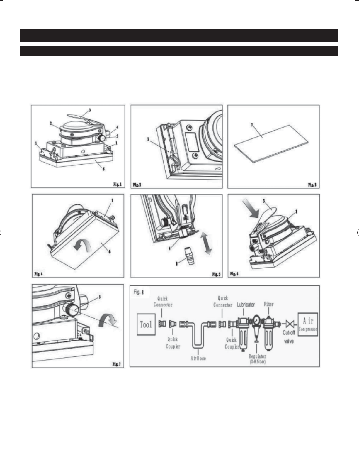
Proper adjustment of the in-line lubricator is performed by
placing a sheet of paper next to the exhaust ports and
holding the throttle open approximately 30 seconds. The
lubricator is properly set when a light stain of oil collects
on the paper. Excessive amounts of oil should be avoided.
It becomes necessary to store the tool for an extended
period of time (overnight, weekend, etc.), it should receive
a generous amount of lubrication at that time. The tool
should be run for approximately 30 seconds to ensure oil
has been evenly distributed throughout the tool. The tool
should be stored in a clean and dry environment.
●It is most important that the tool be properly
lubricated by keeping the air line lubricator filled
and correctly adjusted. Without proper lubrication
the tool will not work properly and parts will wear
prematurely.
●Use correct lubricant in the air line lubricator. The
lubricator should be of low air flow or changing air
flow type, and should be kept filled to the correct
level. Use only recommended lubricants, specially
made for pneumatic applications. Substitutes may
harm the rubber compounds in the tools O-rings
and other rubber parts.
IMPORTANT!
See Figure 8.
If a filter/regulator/lubricator is not installed on the air
system, air operated tools should be lubricated at least
once a day or after 2 hours work with 2 to 6 drops of oil,
depending on the work environment, directly through
the male fitting in the tool housing.
LOADING AND OPERATION
WARNING
Drain the air tank daily. Water in the air line will
damage the tool.
■Clean air inlet filter weekly.
■Line pressure should be increased to compensate for
unusually long air hoses (over 8 metres). The hose
diameter should be 9.52 mm (3/8”) I.D.
■Keep hose away from heat, oil and sharp edges. Check
hose for wear, and make certain that all connections
are secure.
■Air tools should not be used in a potentially explosive
environment.
■There is a risk of explosion or fire due to the material
being processed.
■There is a risk of cutting.
■There is a risk of drawing in or trapping of long hair,
loose clothing.
■WARNING! Cutting off tools shall not be used.
■Personal protection and dust collection device shall be
chosen with regard to the material being worked upon.
■If the tool cannot be used anymore, make sure to
dispose of it so as not to impose hazards to people
and the environment.
■No spare parts are to be used, when these affect the
health and safety of operators.
■There is a risk of a whipping compressed air hose.
MAINTENANCE
WARNING
Disconnect tool from air supply before changing
accessories, servicing or performing maintenance.
Replace or repair damaged parts. Use genuine parts
only. Non-authorized parts may be dangerous.
■Keep the tool safe by regular maintenance.
■Lubricate the tool daily with a few drops of air tool oil
dripped into the air inlet.
■Clean the tool after use. Do not use worn out or
damaged sockets.
■Loss of power or erratic action may be due to the
following:
– Excessive drain on the air line. Moisture or
restriction in the air pipe. Incorrect size or type of
hose connectors. To remedy check the air supply

3
English
– Grit or gum deposits in the tool may also reduce
performance. If your model has an air strainer
(located in the area of the air inlet), remove the
strainer and clean it.
■When not in use, disconnect from air supply, clean tool
and store in a safe, dry, childproof location.
■If the tool cannot be used anymore, make sure to
dispose of it so as not to impose hazards to people
and the environment.
■Maintenance shall be taken weekly.
■Always keep your air tool clean and lubricated. Daily
lubrication is essential to avoid internal corrosion and
possible failure.
■Only lubricants (air tool white oil) recommended by the
manufacturer should be used.
TROUBLESHOOTING
WARNING
If any of the following symptoms appears during your
operating, stop using the tool immediately, or serious
personal injury could result. Only qualified persons or
an authorized service center can perform repairs or
replacement of tool.
Disconnect tool from air supply before attempting repair or
adjustment. When replacing O-rings or cylinder, lubricate
with air tool oil before assembly.
The product is for sanding only, any other use is forbidden.
PROBLEM: Tool runs at normal speed but fails under
load.
POSSIBLE CAUSES
■Motor parts worn.
■Cam clutch worn or sticking due to lack of lubricant.
REMEDIES
■Lubricate clutch housing.
■Check for excess clutch oil. Clutch cases need only
be half full. Overfilling can cause drag on high speed
clutch parts, ie. a typical oiled/lubricated tool requires
1⁄2 ounce of oil.
Grease lubrication
NOTE: Heat usually indicates insufficient grease in
chamber. Severe operating conditions may require
more frequent lubrication.
PROBLEM: Tool runs slowly. Air flows slightly from
exhaust.
POSSIBLE CAUSES
■Motor parts jammed with dirt particles.
■Power regulator in closed position.
■Air flow blocked by dirt.
REMEDIES
■Check air inlet filter for blockage.
■Pour air tool lubricating oil into air inlet as per
instructions.
■Operate tool in short bursts quickly reversing rotation
back and forth where applicable.
■Repeat above as needed.
PROBLEM: Tools will not run. Air flows freely from
exhaust
POSSIBLE CAUSE
One or more motor vanes stuck due to material build
up.
REMEDIES
■Pour air tool lubricating tool into air inlet.
■Operate tool in short bursts of forward and/or reverse
rotation where applicable.
■Tap motor housing gently with plastic mallet.
■Disconnect supply. Free motor by rotating drive shank
manually where applicable
■If tool remains jammed return to service centre.
PROBLEM: Tool will not shut off.
POSSIBLE CAUSE
‘O’ rings throttle valve dislodged from seat inlet valve.
REMEDY
Replace ‘O’ ring .
NOTE: Repairs should be carried out by a qualified
person.

4
English
PARTS LIST
No. Description No. Description No. Description No. Description
1 Trigger 14 pin 27 Rotor key 3x5x13 40 Rubber mount
2 Pin 4*35 15 Spring 28 Sealing Washer 41 Retaining Ring
3 Cap screw M4x6 16 O-ring 11x2 29 Cap screw M5x10 42 Bearing screw M5*10
4 Gasket 17 Nut 30 washer 43 Paper clamp
5 Motor Housing 18 Retainer 8 31 Base 44 Base
6 Retainer 6 19 Cylinder Cap 32 Spring Washer 5 45 Bearing Hang screw
7 Gun Body 20 Ball bearing 6200Z 33 Bolt M5X14 46 Sanding pad
8 O-ring 9.5x1.8 21 O-ring 7.5x1.8 34 Exhaust Cap 47 Oil pot
9 Air inlet plug 22 Pin 3x4 35 Bolt M5X35 48 Quick coupler
10 O-ring 4.5x1.8 23 Cylinder 36 Balancer 49 Anti-dust cap
11 Speed regulator 24 Rotor 37 End plate
12 O-ring 3.5x1.5 25 Blade 38 Spacer
13 O-ring 4x2 26 Rotor shaft 39 Bolt M5x30

TECHTRONIC INDUSTRIES (AUSTRALIA) PTY. LTD.
Level 1. 666 Doncaster Road,
Doncaster, Victoria 3108
Australia.
Tel: 61 3 9840 3226 Fax No.: 613 9840 6133 www.ryobi.com.au
Table of contents
Other Ryobi Sander manuals

Ryobi
Ryobi RS241 User manual

Ryobi
Ryobi ERO-2412V User manual

Ryobi
Ryobi EBS-8021V User manual

Ryobi
Ryobi EBS750 User manual

Ryobi
Ryobi S605D8 User manual

Ryobi
Ryobi RA-DAS150-B User manual

Ryobi
Ryobi RMS180 User manual

Ryobi
Ryobi BD4600 User manual

Ryobi
Ryobi RMS-231 Operation manual

Ryobi
Ryobi S650D User manual