5
Français
FR
GB DE ES IT NL PT DK SE FI NO RU PL CZ HU RO LV LT EE HR SI SK GR TR
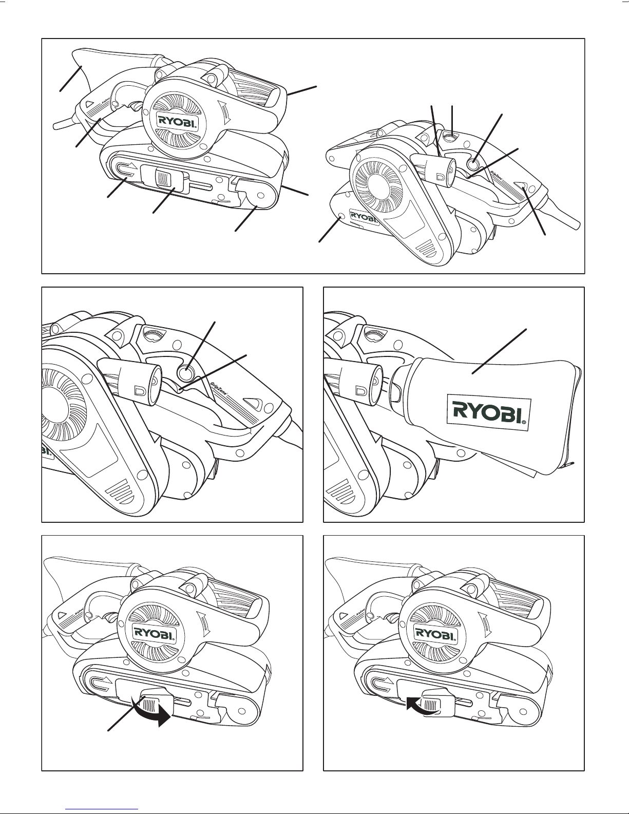
GÂCHETTE (FIG. 1)
Pour mettre en marche ou arrêter cet outil, appuyez ou
relâchez la gâchette (8).
Pour que votre ponceuse fonctionne en continu, enfoncez
le bouton de verrouillage en position "marche" (7) tout en
appuyant sur la gâchette. Pour déverrouiller cette fonction,
appuyez de nouveau sur la gâchette.
La vitesse de la bande abrasive peut être réglée entre 150
et 300 m/min à l'aide du variateur électronique de vitesse
(12).
(1 = vitesse minimale / 6 = vitesse maximale)
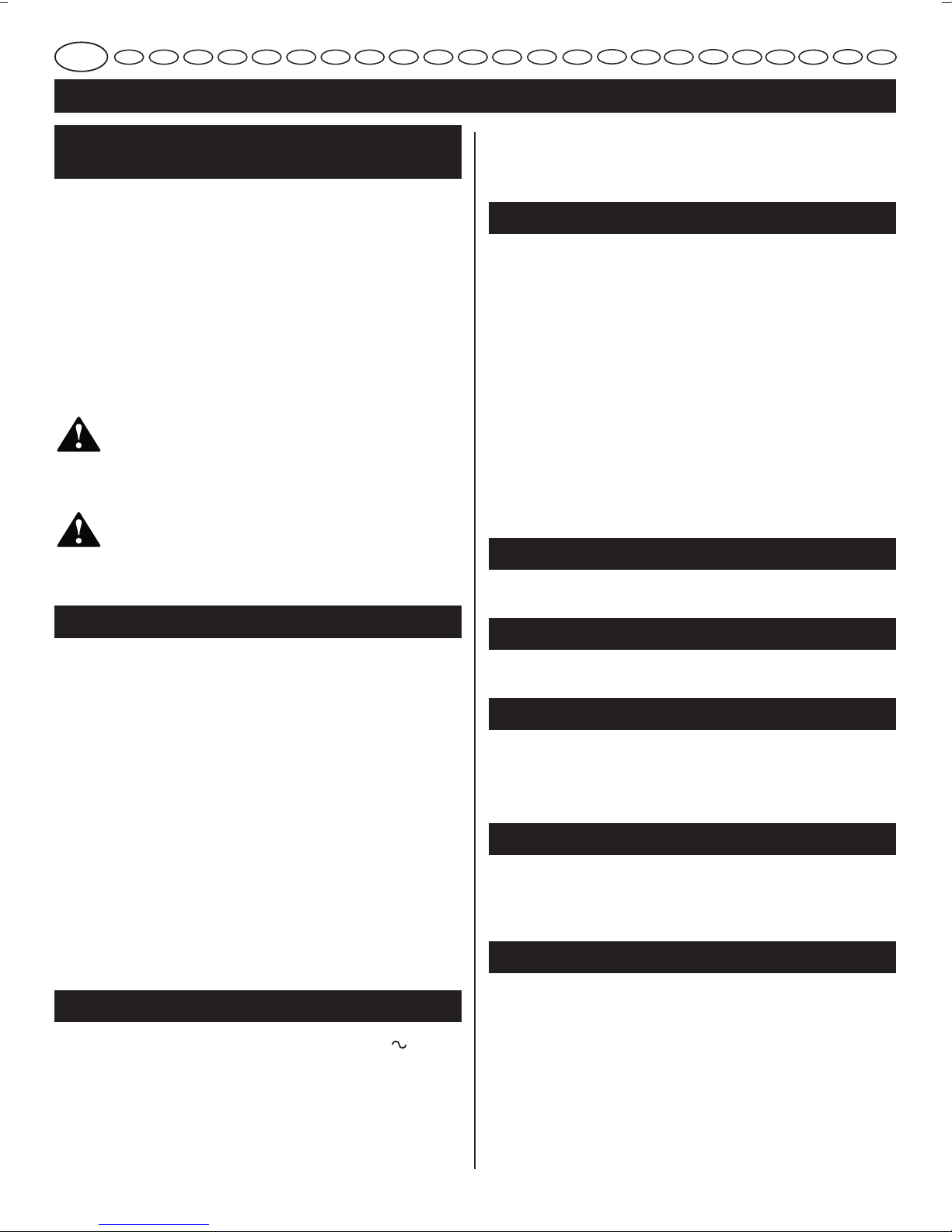
SAC À POUSSIÈRES (FIG. 2)
Nous vous recommandons d'utiliser le sac à poussières (5)
lorsque vous poncez du bois.
Malgré la grande capacité de ce sac, celui-ci doit être vidé
régulièrement.
Pour un nettoyage complet du sac, ouvrez-le à l'aide de la
fermeture Eclair.
AVERTISSEMENT !
N'utilisez pas le sac à poussières lorsque vous
poncez du métal : les étincelles produites
risqueraient d'y mettre le feu.
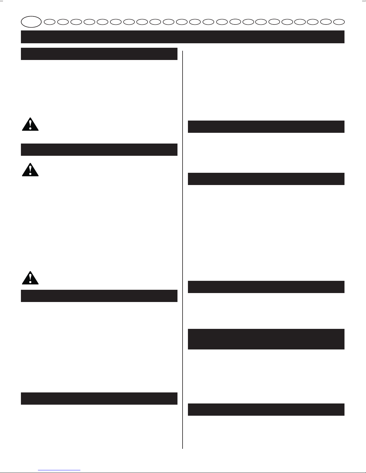
CHANGEMENT DE LA BANDE ABRASIVE
(FIG. 3 À 4)
AVERTISSEMENT !
ASSUREZ-VOUS QUE LA PONCEUSE EST
DÉBRANCHÉE LORSQUE VOUS RETIREZ ET
REMETTEZ EN PLACE UNE BANDE ABRASIVE.
Q
Posez la ponceuse sur le côté et tirez le levier (3) afin de
rétracter le rouleau avant et de relâcher la tension de la
bande (fig. 3).
Q
Tirez sur la bande pour la retirer.
Q
Mettez une nouvelle bande abrasive en place.
REMARQUE :
Assurez-vous que la flèche dessinée
à l'intérieur de la bande est orientée dans la même
direction que celle qui figure sur la ponceuse.
Q
Replacez le levier dans sa position initiale (fig. 4).
AVERTISSEMENT !
Prenez garde de ne pas vous coincer les doigts
pendant l'opération.
POIGNÉE AVANT RÉGLABLE (FIG. 5)
BOUTON DE DÉVERROUILLAGE DE LA POIGNÉE
AVANT
Enfoncez le bouton de déverrouillage de la poignée avant
(14) afin de réglez la poignée avant à la position souhaitée.
RÉGLAGE DE LA POSITION DE LA POIGNÉ AVANT
Tout en maintenant enfoncé le bouton de déverrouillage de
la poignée avant, levez ou baissez la poignée avant pour
la placer à un angle de -15°, 0°, 15° ou 30° selon le travail
que vous souhaitez effectuer. Relâchez ensuite le bouton de
déverrouillage de la poignée avant, et la poignée avant sera
verrouillée à l'angle choisi.
UTILISATION (FIG. 6)
VEILLEZ À NE PAS COUVRIR LES FENTES DE
VENTILATION POUR PERMETTRE UN REFROI-
DISSEMENT CORRECT DU MOTEUR.
ASSUREZ-VOUS QUE LA PIÈCE À USINER NE
COMPORTE NI CLOUS NI AUTRES OBJETS
ÉTRANGERS POUVANT DÉCHIRER LA BANDE.
Tenez votre outil fermement à deux mains. Mettez votre
ponceuse en marche et attendez que le défilement de la
bande abrasive ait atteint sa vitesse maximale. Appliquez
ensuite doucement la ponceuse sur la surface de la pièce
à usiner et effectuez des va-et-vient avec l'outil. Ne forcez
jamais votre outil : le poids de la ponceuse exerce une
pression suffisante. Une pression excessive entrave l'action
abrasive de la bande, ne permet pas un ponçage régulier,
et entraîne une usure précoce aussi bien de la bande que
de l'outil. Retirez toujours l'outil de la pièce à usiner avant
de l'arrêter.
TÉMOIN DE PRÉSENCE TENSION
Cet outil est équipé d'un témoin de présence tension (13)
qui s'allume lorsque l'outil est branché. Ce témoin attire
votre attention sur le fait que l'outil est sous tension et
qu'il se mettra en marche dès que vous appuierez sur
l'interrupteur.
SYSTÈME DE RÉGLAGE AUTOMATIQUE DE
L'ALIGNEMENT DE LA BANDE ABRASIVE
Cet outil intègre un système de réglage automatique de
l'alignement de la bande abrasive.
Placez la ponceuse à l'envers et tenez-la fermement
d'une main, puis mettez-la en marche et observez
l'alignement de la bande abrasive.
EBS-8021V_24lgs_03.indd Sec1:5EBS-8021V_24lgs_03.indd Sec1:5 6/11/09 5:19:09 PM6/11/09 5:19:09 PM