Ryobi RFT254N User manual

WHEELED TRIMMER
OPERATOR’S MANUAL
RFT254N
Important! It is essential that you read the instructions in this manual before
assembling, operating and maintaining this machine.

1
ENGLISH
Your product has been engineered and manufactured to
Ryobi’s high standard for dependability, ease of operation,
and operator safety. Properly cared for, it will give you
years of rugged, trouble-free performance.
WARNING
To avoid serious personal injury, do not attempt to use
this product until you read thoroughly and understand
completely the operator’s manual. Failure to comply
may result in accidents involving electric shock, re,
and/or serious personal injury. Save this operator’s
manual and review frequently for continuing safe
operation and instructing others who may use this
product.
WARNING
The product is not designed for use with any other
Expand-It or similar type attachment. Only use the Pro
Cut attachment supplied with this engine. Using other
attachments will void your warranty.
READ ALL INSTRUCTIONS
GENERAL SAFETY RULES
■Do not allow children or untrained individuals to use
this product.
■Never start or run the engine inside a closed or poorly
ventilated area; breathing exhaust fumes can kill.
■Clear the work area before each use. Remove all
objects, such as rocks, broken glass, nails, wire that
can lead to accidents.
■Always wear eye protection with side shields marked to
comply with standards, along with hearing protection.
Failure to do so could result in objects being thrown
into your eyes and other possible serious injuries.
■Wear head and eye protection to prevent injury from
falling debris.
■Wear heavy, long trousers, boots and gloves. Do not
wear loose fitting clothing, shorts, jewelry of any kind,
or go barefoot.
■Secure long hair so it is above shoulder level to
prevent entanglement in any moving parts.
■Keep all bystanders, children, and pets at least 15 m
away.
■Do not operate this unit when you are tired, ill, or
under the influence of alcohol, drugs, or medication.
■Do not operate in poor lighting.
■Keep firm footing and balance. Do not overreach.
Overreaching can result in loss of balance or exposure
to hot surfaces.
■Keep all parts of your body away from any moving
part.
■Do not touch area around the exhaust, silencer or
engine of the unit; these parts get hot during operation.
■Always stop the engine and remove the spark plug
wire before refuelling, cleaning, maintenance or
storage.
■Inspect the unit before each use for loose fasteners,
fuel leaks, etc.
■Replace any damaged parts before use.
■Check for and tighten any loose parts.
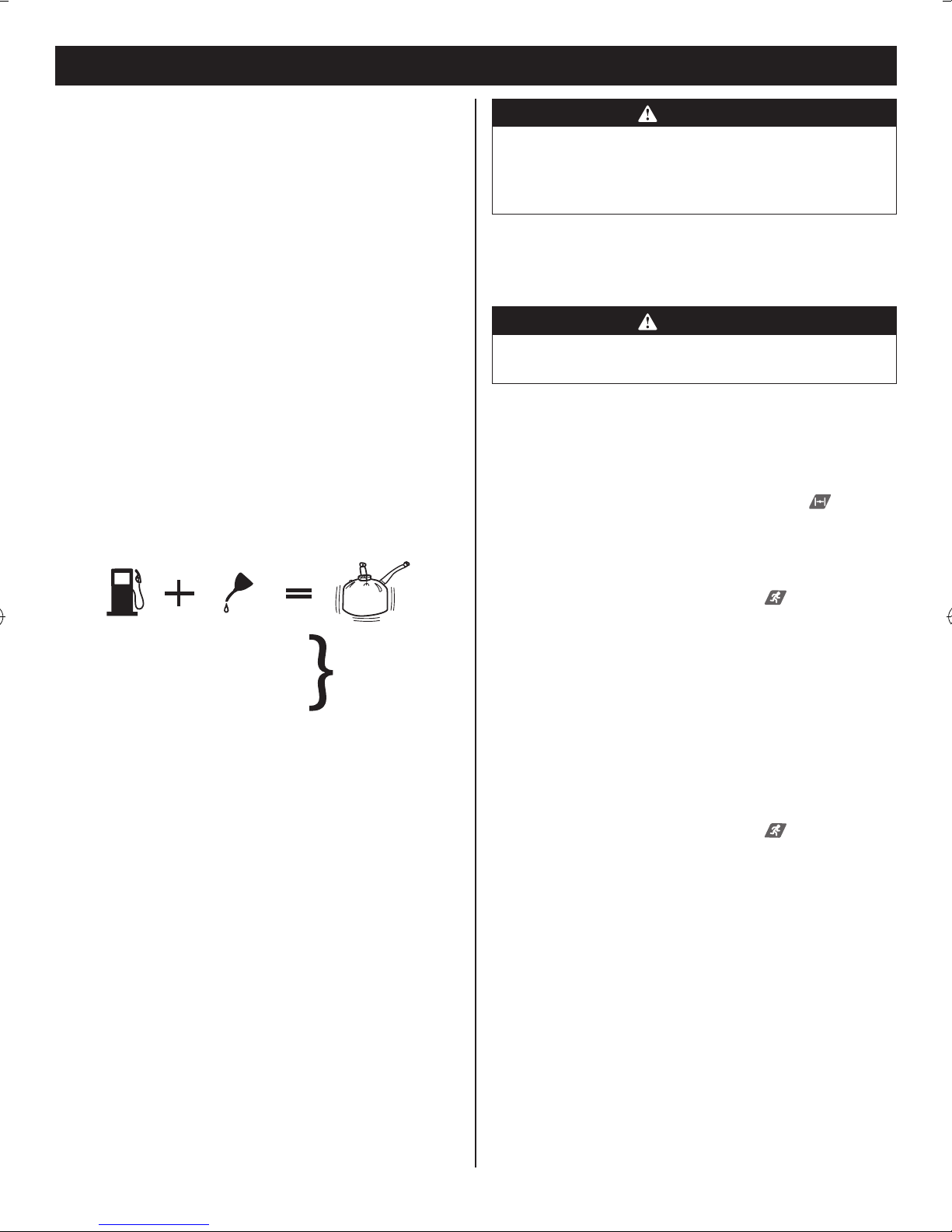
■Mix and store fuel in a container approved for fuel.
■Mix fuel outdoors where there are no sparks or flames.
Wipe up any fuel spillage. Move 9 m away from
refuelling site before starting engine.
■Stop the engine and allow to cool before refuelling or
storing the unit.
■Remove all debris from the work area before
operating.
■Keep bystanders (especially children) away from the
working area by 15 m.
■Allow the engine to cool; empty the fuel tank and
secure the unit from moving before transporting in a
vehicle.
■Wear your protective equipment and observe all
safety instructions. For units equipped with a clutch,
be sure the cutting attachment stops turning when the
engine idles. When the unit is turned off make sure
the cutting attachment has stopped before the unit is
set down.
■Heavy protective clothing may increase operator
fatigue, which could lead to heat stroke. During
weather that is hot and humid, heavy work should be
scheduled for early morning or late afternoon hours
when temperatures are cooler.
WARNING
Inspection after dropping or other impacts:
Thoroughly inspect the product and identify any
affections or damage with it. Any part that is damaged
should be properly repaired or replaced by an
authorised service centre.
SPECIAL SAFETY RULES
TRIMMER
■Replace string head if cracked, chipped, or damaged
in any way. Make sure the trimmer head is properly
installed and securely fastened. Failure to do so can
cause serious injury.
■Make sure all guards, deflectors and handles are

2
ENGLISH
properly and securely attached.
■Use only original manufacturer’s replacement parts.
■Never operate the product without the safety guard in
place and in good condition.
■Never use blades, flailing devices, wire, or rope. Use
only the manufacturer’s replacement line in the cutting
head. Do not use any other cutting attachment. To
install any other type or brand of cutting head to this
wheeled trimmer can result in serious personal injury.
■This product is intended for infrequent use by
homeowners and other occasional users for such
general applications as trimming light and heavy
vegetation, etc. It is not intended for prolonged use.
Prolonged periods of operation can cause circulatory
problems in the user’s hands due to vibration.
RESIDUAL RISKS
■It has been reported that vibrations from hand-held
tools may contribute to a condition called Raynaud’s
Syndrome in certain individuals. Symptoms may
include tingling, numbness and blanching of the
fingers, usually apparent upon exposure to cold.
Hereditary factors, exposure to cold and dampness,
diet, smoking and work practices are all thought to
contribute to the development of these symptoms. It
is presently unknown what, if any, vibrations or extent
of exposure may contribute to the condition. There
are measures that can be taken by the operator to
possibly reduce the effects of vibration:
a) Keep your body warm in cold weather. When
operating the unit wear gloves to keep the hands
and wrists warm.
b) After each period of operation, exercise to
increase blood circulation.
c) Adjusting the working position of the cutting
device. Take frequent work breaks. Limit the
amount of exposure per day.
d) Injuries may be caused or aggravated by prolonged
use of a tool. When using any tool for prolonged
periods, ensure you take regular breaks.
If you experience any of the symptoms of this condition,
immediately discontinue use and see your physician
about these symptoms.
SYMBOLS
The following signal words and meanings are intended to
explain the levels of risk associated with this product.
Symbol Signal Meaning
DANGER: Indicates an imminently
hazardous situation, which,
if not avoided, will result in
death or serious injury.
WARNING: Indicates a potentially
hazardous situation, which,
if not avoided, could result
in death or serious injury.
CAUTION: Indicates a potentially haz-
ardous situation, which, if not
avoided, may result in minor
or moderate injury.
NOTICE: (Without Safety Alert Sym-
bol) Indicates important in-
formation not related to an
injury hazard, such as a
situation that may result in
property damage.
Some of the following symbols may be used on your
tool. Please study them and learn their meaning. Proper
interpretation of these symbols will allow you to operate
the product better and safer.
Safety alert
To avoid serious personal injury, do not
attempt to use this product until you read
thoroughly and understand completely
the operator’s manual.
Danger of ricochet. Keep all bystanders,
especially children and pets, at least
15 m from the operating area.
Use unleaded petrol intended for motor
vehicle use with an octane rating of 91
[(R + M)/2] or higher.
Use 2-stroke oil for air cooled engines.
Mix the fuel mix thoroughly and also each
time before refuelling
Wear eye and hearing protection when
operating this product.
10
Set the choke lever to “RUN” position.
10
Set the choke lever to “FULL” choke
position.
Set the choke lever to Full choke/Run
position
Set the ignition switch to the “I” (ON)
position.

3
ENGLISH
Fully press and release the primer bulb
10 times.
Risk of getting a cut.
Do not install or use any type of blade on
a product displaying this symbol.
10,000
Rotational direction and maximum speed
of the shaft for the cutting attachment.
109
83
Guaranteed sound pressure and sound
power level.
C-Tick compliance mark. Product meets
applicable regulatory requirements.
DESCRIPTION
(REFER TO FIGURE SHEET)
1. Pro Cut string head
2. String head/shaft assembly
3. Mufer
4. Starter grip and rope
5. Choke lever
6. On/Off switch
7. Throttle trigger
8. Handlebar
9. Line carrier
10. Primer bulb
11. Air lter cover
12. Fuel cap
13. Grass deector
14. Mow ball
15. Button
16. Guide recess
17. Knob
18. Lower handlebar
19. Upper handlebar
20. Frame opening
21. Bolt
22. Throttle cable
23. Holes
24. Clip
25. Bolt
26. Wing screw
27. Tab
28. Slot
29. Hole
30. String line
31. Line exit holes
32. Line load holes
33. Top cap
34. Open area
35. Full choke position
36. Run position
37. Hex bolt
38. Direction to tighten the mow ball
39. Direction to loosen the mow ball
40. Air intake area
41. Idle speed screw
42. Air lter element
43. Air lter base
44. Spark plug
45. Spark plug cover
SPECIFICATIONS
Weight
- Without fuel
9.7 kg
Fuel tank volume 620 ml or (0.62 L)
Line cutting length 254 mm
Engine displacement 25.4 cm3
Line diameter 2.7 mm
Maximum engine performance
(in accordance with ISO 8893)
0.67 kW
Maximum rotational frequency
of the spindle
10,000 min-1
Engine speed (rotational
frequency) at recommended
max. spindle rotational
frequency
12,000 min-1
Engine speed (rotational
frequency) at idle
3,200-4,000 min-1
Fuel consumption (in
accordance with ISO 8893) at
max. engine performance
0.54 kg/h
Specic fuel consumption (in
accordance with ISO 8893) at
max. engine performance
0.60 g/kW.h
FEATURES
KNOW YOUR WHEELED TRIMMER
See Figure 1.
The safe use of this product requires an understanding of
the information on the tool and in this operator’s manual
as well as a knowledge of the project you are attempting.
Before use of this product, familiarize yourself with all
operating features and safety rules.

4
ENGLISH
CURVED SHAFT
The curved design of the trimmer shaft allows you to trim
perimeter areas easily.
ERGONOMIC DESIGN
The design of the trimmer provides for easy handling. It is
designed for comfort and ease of grasp when operating in
different positions and at different angles.
GRASS DEFLECTOR
The trimmer includes a grass deector that helps protect
you from ying debris.
ASSEMBLY
UNPACKING
This product requires assembly.
■Carefully remove the product and any accessories
from the box. Make sure that all items listed in the
packing list are included.
NOTE: Be careful not to bend the throttle cable when
unpacking.
WARNING
Do not use this product if any parts on the Packing
List are already assembled to your product when you
unpack it. Parts on this list are not assembled to the
product by the manufacturer and require customer
installation. Use of a product that may have been
improperly assembled could result in serious personal
injury.
■Inspect the product carefully to make sure no
breakage or damage occurred during shipping.
■Do not discard the packing material until you have
carefully inspected and satisfactorily operated the
product.
■If any parts are damaged or missing, please call your
service centre for assistance.
PACKING LIST
Trimmer power head/wheel assembly
Pro Cut string head/shaft assembly
Handle assembly
Hardware bag:
- Operator's manual
- Figure sheet
- Grass deector
- Bottle of 2 stroke oil
- 2.7mm lines (18 pcs)
- Line carrier
- Wing screw
- Knob (4 pcs)
- Bolt (4 pcs)
- Clip (2 pcs)
WARNING
If any parts are damaged or missing do not operate this
product until the parts are replaced. Use of this product
with damaged or missing parts could result in serious
personal injury.
WARNING
Do not attempt to modify this product or create
accessories not recommended for use with this
product. Any such alteration or modication is misuse
and could result in a hazardous condition leading to
possible serious personal injury.
WARNING
To prevent accidental starting that could cause serious
personal injury, always disconnect the engine spark
plug wire from the spark plug when assembling parts.
WARNING
Be certain all knobs are fully tightened before operating
equipment; check them periodically for tightness during
use to avoid serious personal injury.
INSTALLING THE PRO CUT STRING HEAD/SHAFT
ASSEMBLY TO THE TRIMMER POWER HEAD/WHEEL
ASSEMBLY
See Figure 2.
WARNING
Never install, remove, or adjust any attachment while
the engine is running or cutting head is moving. Failure
to stop the engine and cutting head can cause serious
personal injury.
The Pro Cut string head/shaft assembly connects to
the trimmer power head/wheel assembly by means of a
coupler device.
■Loosen the knob on the coupler of the power head
shaft and remove the end cap from the string head/
shaft assembly.
■Push in the button located on the string head shaft.

5
ENGLISH
Align the button with the guide recess on the power
head coupler and slide the two shafts together. Rotate
the string head shaft until the button locks into the
positioning hole.
NOTE: If the button does not release completely in
the positioning hole, the shafts are not locked into
place. Slightly rotate from side to side until the button
is locked into place. If needed, turn the trimmer head
which will aid in the insertion of the shaft.
■Tighten the knob securely.
INSTALLING LOWER HANDLEBAR
See Figure 3.
■Remove two handlebar knobs and two bolts from the
hardware bag.
■Place the lower handle bar into the openings on the
trimmer power head/wheel assembly as shown.
NOTE: Do not allow throttle cable to become pinched
when installing the handlebar.
■Insert the bolts through the holes in the handlebar and
frame.
■Install the lower handlebar knobs and tighten securely.
INSTALLING UPPER HANDLE BAR
See Figure 4.
■Remove two handle bar knobs and bolts from the
hardware bag.
■Position upper handlebar onto lower handlebar. Make
sure the throttle cable and throttle trigger are on the
right side as shown.
■Insert bolt through plastic clip, then through holes.
NOTE: Do not allow throttle cable to become pinched
when installing the handlebar.
■Align the holes in the clip, the upper handlebar and
lower handlebar.
■Install bolt as shown.
■Thread handlebar knob onto bolt and tighten securely.
Repeat with other side.
ATTACHING THE GRASS DEFLECTOR
See Figure 5.
WARNING
The line cutting blade on the grass deector is sharp.
Avoid contact with the blade. Failure to avoid contact
can result in serious personal injury.
■Remove the wing screw from the grass deflector.
■Insert the tab on the mounting bracket in the slot on
the grass deflector.
■Align the screw hole in the mounting bracket with the
screw hole in the grass deflector.
■Insert the wing screw through the mounting bracket
and into the grass deflector.
■Tighten the screw securely.
INSTALLING LINE IN PRO CUT STRING HEAD
See Figure 6.
Use monolament 2.7 mm (diameter) line. Use quality
monolament replacement line for best performance.
■Stop the engine and disconnect the spark plug wire.
■Gather two of the pre-cut lengths of trimmer line
provided or cut two pieces of trimmer line in 25.4 cm
lengths.
■Insert the lines into the load slots located on the sides
of the string head. Line should be pushed in until
approximately 2 cm protrudes from the holes on the
top of the string head.
■Remove old line by pulling it from the holes located on
the top of the string head.
WARNING
Do not remove screws or disassemble string head.
If head is opened, compression springs could y out
toward operator and result in serious injury.
INSTALLING LINE CARRIER
See Figure 7.
The line carrier snaps onto the upper handlebar on the
side opposite the throttle cable and is used to hold pre-cut
pieces of trimmer line.
NOTE: Do not install the carrier where it could interfere
with the throttle cable or where it could cover any of the
warning icons or labels.
To install line, remove top cap, insert line into carrier, and
replace cap. To remove line for use, pull from open area
on front of carrier.
OPERATION
FUEL AND REFUELLING
Handling the fuel safely
■Always handle fuel with care. It is highly flammable.
■Always refuel outdoors where there are no sparks and
flames. Do not inhale fuel vapours.
■Do not let petrol or lubricant come in contact with your
skin.
■Keep petrol and lubricant away from the eyes. If petrol
or lubricant comes in contact with the eyes, wash
them immediately with clean water. If irritation is still

6
ENGLISH
present, see a doctor immediately.
■Clean up spilled petrol immediately.
Mixing the fuel
■This product is powered by a 2-stroke engine and
requires pre-mixing petrol and 2-stroke lubricant.
Premix unleaded petrol and 2-stroke engine lubricant
in a clean container approved for petrol.
■This engine is certified to operate on unleaded petrol
intended for motor vehicle use with an octane rating of
91 ([R + M]/2) or higher.
■Do not use any type of pre-mixed petrol/lubricant from
fuel service stations.
■Use synthetic 2-stroke lubricant only. Do not use
automotive lubricant or 2-cycle outboard lubricant.
■Mix 2% synthetic 2-stroke lubricant into the petrol.
This is a 50:1 ratio.
■Mix the fuel thoroughly and also each time before
refuelling.
■Mix in small quantities. Do not mix quantities larger
than usable in a 30-day period. A synthetic 2-stroke
lubricant containing a fuel stabiliser is recommended.
1 Litre + 20 ml =
2 Litres + 40 ml =
3 Litres + 60 ml = 50:1 (2%)
4 Litres + 80 ml =
5 Litres + 100 ml =
Filling the tank
■Clean surface around fuel cap to prevent
contamination.
■Loosen the fuel cap slowly to release pressure and to
keep fuel from escaping around the cap.
■Carefully pour fuel mixture into the tank. Avoid
spillage.
■Prior to replacing the fuel cap, clean and inspect the
gasket.
■Immediately replace fuel cap and hand tighten. Wipe
up any fuel spillage. Move 9 m away from refuelling
site before starting engine.
NOTE: It is normal for smoke to be emitted from a new
engine during and after rst use.
WARNING
Always shut off engine before fuelling. Never add fuel
to a machine with a running or hot engine. Move at
least 9 m (30 ft) from refuelling site before starting the
engine. Do not smoke.
STARTING AND STOPPING
See Figures 8-11.
WARNING
Never start or run the engine inside a closed or poorly
ventilated area; breathing exhaust fumes can kill.
To start a cold engine
1. Lay the product on a at, bare surface.
2. Set the ignition switch to the "I" (ON) position.
3. Push the primer bulb approximately 10 times.
4. Set the choke lever to full choke position .
5. Hold the product tight with left hand and pull the starter
grip with right hand in a quick, rm and consistent
upward motion (no more than 6 pulls) until engine
attempts to start. Do not squeeze the throttle trigger.
6. Set the choke lever to run position .
7. Pull the starter grip with a quick rm and consistent
upward motion (no more than 4 pulls) until the engine
starts. Do not squeeze the throttle trigger.
8. When the engine starts, allow the engine to run for 10
seconds, then squeeze the throttle trigger.
NOTE: If engine does not start, return to step 4 and
repeat the steps.
To start a warm engine
1. Lay the product on a at, bare surface.
2. Set the ignition switch to the "I" (ON) position.
3. Set the choke lever to run position .
4. Hold the product tight with left hand and pull the starter
grip with right hand in a quick, rm and consistent
upward motion (no more than 4 pulls) until engine
starts. Do not squeeze the throttle trigger.
5. When the engine starts, allow the engine to run for 10
seconds, then squeeze the throttle trigger.
NOTE: If engine does not start, return to step 4 of "To
start a cold engine" and repeat the steps.
To stop the engine
1. Release the trigger.
2. Push the switch to the "O" (OFF) position.
CUTTING TIPS
See Figure 12.
■Keep a firm grip with both hands while in operation.

7
ENGLISH
■If grass becomes wrapped around the string head,
STOP THE ENGINE, disconnect the spark plug wire,
and remove the grass.
■Use the tip of line to do the cutting; do not force string
head into uncut grass.
■Wire and picket fences cause extra line wear, even
breakage. Stone and brick walls, curbs, and wood
may wear line rapidly.
■Avoid trees and shrubs. Tree bark, wood moldings,
siding, and fence posts can easily be damaged by the
line.
TRANSPORTING THE UNIT
■Drain all fuel from tank into a container approved for
fuel. Run engine until it stops.
■Push the On/Off switch to the “O” (off) position.
■Allow the engine and exhaust to cool before placing
in the vehicle.
■Secure the unit against falling or sudden movement.
MAINTENANCE
WARNING
Use only original manufacturer's replacement parts,
accessories and attachments. Failure to do so can
cause possible injury, poor performance and may void
your warranty.
WARNING
Before inspecting, cleaning, or servicing the machine,
shut off engine, wait for all moving parts to stop, and
disconnect spark plug wire and move it away from
spark plug. Failure to follow these instructions can
result in serious personal injury or property damage.
GENERAL MAINTENANCE
■Avoid using solvents when cleaning plastic parts.
Most plastics are susceptible to damage from various
types of commercial solvents and may be damaged
by their use. Use clean cloths to remove dirt, dust,
lubricant, grease, etc.
■You may make adjustments and repairs described
here. For other repairs, have the trimmer serviced by
an authorised service agent.
■Consequences of improper maintenance may
include excess carbon deposits resulting in loss of
performance and discharge of black oily residue
dripping from the silencer.
■ Make sure all guards, straps, deectors and handles
are properly and securely attached to avoid the risk of
personal injury.
ACCESSING THE STRING HEAD
See Figure 13.
■Rotate mow ball with hex bolt clockwise to loosen.
■Remove mow ball with hex bolt from shaft.
To reattach mow ball:
■Slide mow ball with hex bolt onto shaft.
■Rotate counter clockwise to tighten.
CLEANING THE AIR INTAKE AREA
See Figure 14.
WARNING
If the air intake area becomes clogged, air circulation
will decreased and engine performance will be suffer.
To clean:
■Stop the wheeled trimmer and disconnect the spark
plug wire.
■Allow the unit to cool, if necessary.
■Using a nylon brush, remove dirt and debris between
engine cover and fuel tank.
IDLE SPEED ADJUSTMENT
See Figure 15.
WARNING
The cutting head will move when adjusting the idle
speed. Wear all protective clothing and keep all
bystanders, children, and pets at least 50 ft. away.
Make adjustments with the unit supported by hand
so that the cutting head does not contact the ground
or any object. Keep all parts of your body away from
the cutting head and mufer. Failure to follow these
instructions could result in serious personal injury.
If the cutting attachment turns at idle, the idle speed screw
needs adjusting on the engine. Turn the idle speed screw
counterclockwise to reduce the idle RPM and stop the
cutting attachment movement. If the cutting attachment
still moves at idle speed, contact a service dealer for
adjustment and discontinue use until the repair is made.

8
ENGLISH
WARNING
The cutting attachment should never turn at idle. Turn
the idle speed screw counterclockwise to reduce the
idle RPM and stop the cutting attachment, or contact a
service dealer for adjustment and discontinue use until
the repair is made. Serious personal injury could result
from the cutting attachment turning at idle.
CLEANING THE AIR FILTER ELEMENT
See Figure 16.
■Stop the trimmer.
■Remove the spark plug cover.
■Loosen the air filter cover by turning the knob
counterclockwise.
■Remove the air filter cover.
■Remove the air filter element and clean it with warm
soapy water. Then, rinse and let it dry completely.
■Work two drops of lubricant into the air filter.
■Replace the air filter element (fits only one way).
■Replace the air filter cover. Tighten it by turning the
knob clockwise.
■Replace the spark plug cover.
NOTE: Make sure the lter is seated properly inside the
cover. Installing the lter incorrectly will allow dust/debris
to enter the engine, causing rapid engine wear.
NOTE: For best performance, the air lter element should
be replaced once each year.
CHECKING THE FUEL CAP
WARNING
A leaking fuel cap is a re hazard and must be replaced
immediately.
The fuel cap contains a non-serviceable lter and a
check valve. A clogged fuel lter causes poor engine
performance. If performance improves when the fuel cap
is loosened, the check valve may be faulty or the lter may
be clogged. Replace the fuel cap if necessary.
REPLACING THE SPARK PLUG
See Figure 17.
This engine uses a NGK BPMR7A or a Champion RCJ6Y
spark plug. Use an exact replacement and replace
annually. Follow these steps to replace the spark plug.
■Remove the spark plug cover.
■Loosen the spark plug by turning it counterclockwise
with a 5/8 in. socket. Remove the spark plug.
■Hand thread the new spark plug. Turn it clockwise and
tighten with a socket. Do not overtighten.
WARNING
Do not cross-thread the spark plug. Cross threading
will seriously damage the product.
CLEANING THE SPARK ARRESTOR
Follow these steps to clean the spark arrestor.
■Locate the spark arrestor through the hole in the
muffler exit hole.
■Remove the spark arrestor using needle-nose pliers.
■Clean the spark arrestor with a small wire brush.
■Replace the spark arrestor.
STORING THE PRODUCT
Short term storage
■Clean all foreign material from the product.
■Store the product in a well-ventilated place that is
inaccessible to children.
Long term storage (1 month or longer)
■Drain all of the fuel from the tank into a container
approved for gasoline.
■Run the engine until it stops.
■Clean all foreign material from the product.
■Store the product in a well-ventilated place that is
inaccessible to children. Keep away from corrosive
agents such as garden chemicals and de-icing salts.
■Abide by all ISO and local regulations for the safe
storage and handling of fuel.
20131009v2

9
ENGLISH
TROUBLESHOOTING
Problem Possible cause Solution
Engine will not start.
1. Switch set to the "O" (OFF) position.
2. No spark
3. No fuel.
4. Flooded engine.
5. Starter rope pulls harder now than
when new.
6. Old fuel.
1. Set switch to the "I" (ON) position.
2. The spark plug may be damaged. Remove it and
check for dirt and cracks. Replace with a new spark plug
if needed.
3. Push primer bulb until the bulb is full of fuel. If the bulb
does not ll, the primary fuel delivery system is blocked.
If the primer bulb lls, the engine may be ooded. (See
next item.)
4. Ensure the on/off switch is in the “O” (off) position.
Remove the spark plug from the engine and the spark
plug boot. Turn the product so that the spark plug hole is
aimed at the ground. Make sure the choke lever is set to
and pull the starter cord 10 to 14 times. This clears
excess fuel from the engine. Clean and reinstall the spark
plug. With the throttle trigger fully depressed, pull the
starter cord 3 times. If the engine does not start, set the
choke lever to and follow normal starting instructions.
If the engine still fails to start, repeat the procedure with
a new spark plug.
5. Contact an authorised service dealer.
6. Only use fresh fuel mixed with recommended oil. Fuel
over 30 days old may prevent the unit from starting.
Engine does not reach full speed
and emits excessive smoke.
1. Check lubricant fuel mixture.
2. Air lter is dirty.
3. Spark arrestor screen is dirty.
1. Use fresh fuel and the correct 2-stroke lubricant mix.
2. Clean the air lter according to the instructions in the
Maintenance section.
3. Contact an authorised service dealer.
Engine starts, runs, and
accelerates but will not idle
Idle speed screw on carburetor needs
adjustment.
Turn idle speed screw clockwise to increase idle speed.
See Figure 15.
Retaining cap hard to turn.
Screw threads are dirty or damaged. Clean the threads and lubricate with grease.
If this does not solve the problem, replace the retaining
cap.
Grass wraps around the
trimmer head assembly and the
attachment shaft.
1. Cutting tall grass at ground level.
2. Operating the product at partial
throttle.
1. Cut tall grass from the top down.
2. Operate the product at full throttle.
Lubricant drips from silencer.
1. Operating the product at partial
throttle.
2. Check lubricant/fuel mixture.
3. Air lter is dirty.
1. Operate the product at full throttle.
2. Use fresh fuel and the correct 2-stroke lubricant mix.
3. Clean the air lter according to the instructions in the
Maintenance section.

Techtronic Industries (Australia) Pty. Ltd.
Level 1, 660 Doncaster Road
Doncaster, VIC 3108, Australia
Techtronic Industries New Zealand Ltd.
18-26 Amelia Earhart Avenue
Mangere, Auckland 2022, New Zealand
960720011-02
20131009v2
Table of contents
Other Ryobi Trimmer manuals

Ryobi
Ryobi RBC36X26B User manual

Ryobi
Ryobi RY24001, RY24021 User manual

Ryobi
Ryobi RLT254CDSO User manual

Ryobi
Ryobi RLT2925 User manual

Ryobi
Ryobi RY402011 User manual

Ryobi
Ryobi P600 User manual

Ryobi
Ryobi RHT-600R User manual

Ryobi
Ryobi Expand-It ABCLT04G User manual

Ryobi
Ryobi PowerPlus HT12V User manual

Ryobi
Ryobi P20102 User manual

Ryobi
Ryobi RLT-552 Operation manual

Ryobi
Ryobi P2008 User manual

Ryobi
Ryobi RLT26CDSE User manual

Ryobi
Ryobi RFT254 User manual

Ryobi
Ryobi RLT-300 Operation manual

Ryobi
Ryobi P20018 User manual

Ryobi
Ryobi 150r User manual

Ryobi
Ryobi CLT1223 User manual

Ryobi
Ryobi Expand-it RXAHT01 User manual

Ryobi
Ryobi RY39506 User manual