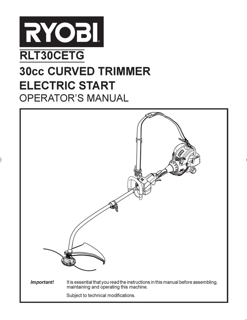
Ryobi RLT30CESA User manual

ORIGINAL INSTRUCTIONS
RLT30CESA
30cc PETROL LINE TRIMMER
Important!
It is essential that you read the instructions in this manual before
assembling, maintaining and operating this machine.

1
English (Original Instructions)
SYMBOLS
Important: Some of the following symbols may be used on your tool. Please study them and learn their meaning.
Proper interpretation of these symbols will allow you to operate the tool better and safer.
NAME EXPLANATION
Safety Alert Symbol Precautions that involve your safety.
Read Your Operator's Manual
Your manual contains special messages to bring attention to
potential safety concerns as well as operating and servicing
information. Please read all the information carefully to ensure
satisfaction and safe use.
Eye, Head and Ear
Protection
Thrown objects can cause severe eye and head injury. Wear eye
protection and helmet when operating this product. Wear hearing
protection during extended period of operation.
Keep Bystanders Away Keep all bystanders, especially children and pets, at least 15m
from the operating area.
Thrown Objects Thrown objects can cause severe injury. Wear protective
clothing and boots.
No blade Do not install any type of blade on this unit.
Do not use toothed blade This unit is not intended for use with a toothed saw type blade.
RPM Decal Rotational direction and maximum speed of the shaft for the
cutting attachment.
Boots Wear non-slip safety footwear when using this equipment.
Gloves Wear non-slip, heavy-duty gloves.
No Smoking Do not smoke when mixing fuel or filling fuel tank.
Petrol Use unleaded gasoline intended for motor vehicle use with an
octane rating of 91 ([R+M]/2) or higher.
Lubricant Use synthetic 2-stroke lubricant for air cooled engines.
Mix Petrol and Lubricant Mix the fuel mix thoroughly and also each time before
refuelling.
Switch
On/Off Switch
I = ON to Run
O = OFF to Stop
Regulatory Compliance Mark (RCM). Product meets applicable
regulatory requirements.

2
English (Original Instructions)
Your new trimmer has been engineered and manu-
factured to Ryobi’s high standard for dependability, ease
of operation, and operator safety. Properly cared for, it
will give you years of rugged, trouble-free performance.
INTENDED USE
This product is only intended for use outdoors in a well
ventilated area.
The product is intended for cutting long grass, pulpy
weed, brush and similar vegetation at or about ground
level. The product should not be used to cut or trim
hedges, bushes or other vegetation where the cutting
plane is not parallel to the ground surface.
WARNING
To reduce the risk of injury, the user must read
and understand the operator’s manual.
WARNING
Do not attempt to operate this trimmer until you
have read thoroughly and understood completely
all instructions, safety rules etc contained in
this manual. Failure to comply may result in
accidents involving fire, electric shock or serious
personal injury. Save operator’s manual and
review frequently for continuing safe operation,
and instructing others who may use this tool.
READ ALL INSTRUCTIONS.
GENERAL SAFETY RULES
nFor safe operation, read and understand all
instructions before using the trimmer. Follow all safety
instructions. Failure to follow all safety instructions
listed below, can result in serious personal injury.
nDo not allow children or untrained individuals to use
this unit.
nNever start or run the engine in a closed or poorly
ventilated area; breathing exhaust fumes can kill.
nClear the work area before each use. Remove all
objects such as rocks, broken glass, nails, wire,
or string which can be thrown or become entangled in
the bump head.
nWear full eye and hearing protection while operating
this unit.
nWear heavy long pants, boots, and gloves. Do not
wear loose fitting clothing, short pants, jewellery of
any kind, or use with bare feet.
nSecure long hair so it is above shoulder level to
prevent entanglement in any moving parts.
nKeep all bystanders, children, and pets at least 15 m
away.
nDo not operate this unit when you are tired, ill, or
under the influence of alcohol, drugs, or medication.
nDo not operate in poor lighting.
nKeep firm footing and balance. Do not overreach.
Overreaching can result in loss of balance or
exposure to hot surfaces.
nKeep all parts of your body away from any moving part.
nDo not touch area around the muffler or cylinder of
the trimmer, these parts get hot from operation.
nAlways stop the engine and remove the spark plug
wire before making any adjustments or repairs except
for carburetor adjustments.
nInspect the unit before each use for loose fasteners,
fuel leaks, etc. Replace any damaged parts before use.
nKeep the tool well maintained, fasteners tightened
and worn parts replaced.
nMix and store fuel in a container approved for fuel.
nMix fuel outdoors where there are no sparks or flames.
Wipe up any fuel spillage. Move 9 m away from
refueling site before starting engine.
nStop the engine and allow to cool before refueling or
storing the unit.
nAllow the engine to cool; empty the fuel tank and
secure the unit from moving before transporting in a
vehicle.
nDebris, when hit by the line, can travel significant
distances. Remove debris from the working area
before operating.
nOperating similar tools nearby increases risk of injury.
nUse of hearing protection reduces the ability to hear
warnings (shouts or alarms). The operator must pay
extra attention to what is going on in the working
area.
nIf working in an area where there is a risk of falling
objects, head protection must be worn.
SPECIFIC SAFETY RULES FOR TRIMMER USE
nReplace bump head if cracked, chipped, or damaged
in anyway. Be sure the bump head is properly
installed and securely fastened. Failure to do so can
cause serious injury.
nMake sure all guards, straps, deflectors and handles
Guaranteed sound power level is 113 dB.


3
English (Original Instructions)
3
are properly and securely attached.

nUse only the manufacturer's replacement line in the
cutting head. Do not use any other cutting attachment.
nNever operate unit without the safety guard in place
and in good condition.
nMaintain a firm grip on both handles while trimming.
Keep bump head below waist level. Never cut with
the bump head located over 76 cm or more above the
ground.
nThis product is very noisy when operating, to prevent
long term hearing damage, wear hearing protection
and keep other persons 15m away from the work
area. Operating similar tools nearby increases risk of
injury.
WARNING
The product is not intended for use by persons
(including children) with reduced physical, sensory
or mental capabilities, or lack of experience
and knowledge, unless they have been given
supervision or instruction concerning use of the
appliance by a person responsible for their safety.
Children should be supervised to ensure that they do
not play with the product.
SPECIFICATION
RLT30CESA
Weight (kg)
- Without fuel, cutting attachment and harness 5.45
- Without fuel with bump head 5.75
Fuel tank volume [cm3 or (L)] 415 or (0.415)
Cutting swath (mm) 432
Engine displacement (cm3/ cc) 30
Line diameter for Reel EasyTM Head (mm) 2.4
Maximum engine performance (kW) 0.75
Maximum rotational frequency of the spindle (min-1) 12,000
Engine speed (rotational frequency) at recommended max.
spindle rotational frequency
(min-1) 12,000
Engine speed (rotational frequency) at idle (min-1) 2,800-3,800
Fuel consumption at max. engine performance [kg/h or (L/h)] 0.42 or (0.58)
Specific fuel consumption at max. engine performance [g/kW.h or (L/kW.h)] 560 or (0.77)
Vibration
Front handle (lawn trimmer/brushcutter)
- Idling (m/s2)1.9
- Racing (m/s2)6.3
- equivalent vibration total value (m/s2)4.6
Rear handle (lawn trimmer/brushcutter)
- Idling (m/s2)2.2
- Racing (m/s2)10.4
- equivalent vibration total value (m/s2)7.6

4
English (Original Instructions)
Uncertainity (m/s2)1.5
Noise emission
A-weight emission sound pressure level at the operator's position (lawn trimmer/brushcutter)
- Idling dB(A) 86.5
- Racing dB(A) 103.4
- equivalent vibration total value dB(A) 100.5
A-weight emission sound power level
- Idling dB(A) 91.3
- Racing dB(A) 110.9
- equivalent vibration total value dB(A) 110.9
Uncertainity dB(A) 2.5
4
DESCRIPTION
1. Primer Bulb
2. Choke Dial
3. Fuel Cap
4. Starter Grip
5. Throttle Lock
6. On / Off Switch
7. Throttle Trigger
8. Rear Handle
9. Front Handle
10. Shaft
11. Grass Deflector
12. Reel EasyTM
13. Cutting Line
14. Idle Speed Screw
15. Knob
16. Hanger Cap
17. Latch
18. Screw
19. Barrier
20. M-clamp, plastic
21. Pin
22. Wrench
ASSEMBLY
Please refer to Fig. 1.
UNPACKING
This product requires assembly.
nCarefully remove the tool and any accessories from
the box. Make sure that all items listed in the packing
list are included.
nInspect the tool carefully to make sure no breakage
or damage occurred during shipping.
nDo not discard the packing material until you have
carefully inspected and satisfactorily operated the
tool.
WARNING
If any parts are damaged or missing, do not
operate this tool until the parts are replaced.
Failure to heed this warning could result in
serious personal injury.
WARNING
Do not attempt to modify this product or create
accessories not recommended for use with this
product. Any such alteration or modification is
misuse and could result in a hazardous condition
leading to possible serious personal injury.
WARNING
To prevent accidental starting that could cause
serious personal injury, always disconnect the
engine spark plug wire from the spark plug when
assembling parts.
WARNING
Never attach or adjust any attachment while
power head is running. Failure to stop the engine
may cause serious personal injury.
ATTACHING FRONT HANDLE (Fig. 2a)
nRemove the securing screws and bracket from the
front handle.
nAlign the pin into upper shaftslot.
nInstall the front handle onto the upper shaft.
NOTE: The front handle should tilt slightly towards
the operator when correctly fitted.

5
English (Original Instructions)
nPlace the screws through the front handle and
securely tighten them into the captive nuts on the
bracket.
NOTE: Do not attempt to remove or modify the
spacer, this spacer limits the upper position of the
handle grip.
ATTACHING SAFETY GUARD (Fig. 2a)
nLoosen the hex nut with wrench.
nPlace safety guard over shaft and bracket.
nTighten hex nut securely.
INSTALLING THE REEL EASY LINE TRIMMER HEAD
(Fig. 2b-2c)
nRemove the paper tube .
nOpen the Reel Easy Line Trimmer Head by
depressing the latches on each side. The contents of
the line trimmer head are spring loaded, so keep your
other hand over the line trimmer head cover while
depressing the latches.
nRemove the line trimmer head cover, bump knob, and
line spool and set aside.
nPlace the cutting head housing on the drive shaft.
Make sure the housing is fully seated.
nInstall the hex bolt to secure the line trimmer head
to the drive shaft. Tighten by using the hex-shaped
opening on the inside of the bump knob.
NOTE: Only use the bump knob to tighten the bolt.
The use of other tools may allow over tightening of
the bolt, which could damage the line trimmer head.
nReinstall the bump head spring into the line trimmer
head and push down to seat.
nReinstall the line spool. For the curved shaft
attachment with the Reel Easy cutting head the spool
should be placed so “This side out for curved shaft” is
visible on the line spool.
nReplace the bump knob by inserting it into the centre
of the line spool.
nReplace the line trimmer head cover, aligning latches
with openings in the line trimmer head. Press cover
and line trimmer head together until both latches
snap into openings securely.
nInstall line as described in the next section of this
manual.
INSTALLING LINE IN REEL EASY LINE TRIMMER
HEAD (Fig. 8)
nUse 2.4mm diameter monofilament line.
nStop the engine and disconnect the spark plug wire.
nCut one piece of line approximately 6.0 meters in
length.
nRotate the bump knob on line trimmer head until line
on the centre of the bump knob aligns with arrows on
top of line trimmer head.
nInsert one end of line into eyelet located on the side
of the line trimmer head and push until line comes
out through the eyelet on the other side. Continue
to push line through the line trimmer head until the
middle section of the line is inside the line trimmer
head and line outside the line trimmer head is evenly
divided on each side.
nRotate the knob on the line trimmer head to wind
the line. If using a curved shaft attachment, the knob
should be rotated counterclockwise.
nWind the line until approximately 20cm remains
protruding from the line trimmer head.
nReplace the spark plug boot
ATTACHING THE POWER HEAD TO TRIMMER
ATTACHMENT (Fig. 2a)
nFollow these steps to connect the trimmer attachment
to the upper shaft.
nLoosen the knob by turning it counter clockwise.
nAlign the button on the lower shaft with the guide
recess on the upper shaft.
nSlide the lower shaft into the upper shaft until the
attachment shaft clicks into place.
nTighten the knob securely by turning it clockwise.
REMOVING THE TRIMMER ATTACHMENT FROM THE
UPPER SHAFT
nFollow these steps to remove the attachment from
the upper shaft.
nLoosen the knob by turning it counterclockwise.
nPush the button while pulling out the attachment.
OPERATION
Read the operation manual and follow all
warnings and safety instructions.
Wear eye, hearing, and head protection.
Keep all bystanders, especially children and
pets, at least 15 m from the operating area.
FUEL AND REFUELING
HANDLING THE FUEL SAFELY
nAlways handle fuel with care, it is highly flammable.
nAlways refuel outdoors where there are no sparks
and flames. Do not inhale fuel vapors.
5

6
English (Original Instructions)
nDo not let petrol or lubricant come in contact with
your skin.
nKeep petrol and lubricant away from the eyes. If
petrol or lubricant comes in contact with the eyes,
wash them immediately with clean water. If irritation is
still present, see a doctor immediately.
nClean up spilled petrol immediately.
nAlways transport and store fuel in a container
approved for petroleum.
MIXING THE FUEL (Fig. 3)
nThis product is powered by a 2-stroke engine and
requires pre-mixing petrol and 2-stroke lubricant. Pre-
mix unleaded petrol and 2-stroke engine lubricant in a
clean container approved for petrol.
nThis engine is certified to operate on unleaded petrol
intended for automotive use with an octane rating
of 91 ([R + M] / 2) or higher.
nDo not use any type of pre-mixed petrol / lubricant
from fuel service stations, this includes the pre-
mixed petrol / lubricant intended for use in mopeds,
motorcycles, etc.
nUse synthetic 2-stroke lubricant only. Do not use
automotive lubricant or 2-stroke outboard lubricant.
nMix 2% synthetic 2-stroke lubricant into the petrol.
This is a 50:1 ratio.
nMix the fuel thoroughly and also each time before
fueling.
nMix in small quantities. Do not mix quantities larger
than usable in a 30 day period. Synthetic 2-stroke
lubricant containing a fuel stabilizer is recommended.
FILLING THE TANK
WARNING
Check for fuel leaks. If any are found, correct
them before using the trimmer to prevent fire or
burn injury.
nClean surface around fuel cap to prevent
contamination.
nLoosen fuel cap slowly to release pressure and to
keep fuel from escaping around the cap.
nCarefully pour fuel mixture into the tank. Avoid spillage.
nPrior to replacing the fuel cap, clean and inspect
the gasket.
nImmediately replace fuel cap and hand tighten.
Wipe up any fuel spillage. Move 9 m away from
refueling site before starting engine.
Note: It is normal for smoke to be emitted from a new
engine during and after first use.
WARNING
Always shut off engine before fueling. Never add
fuel to a machine with a running or hot engine.
Move at least 9 m from refueling site before
starting engine. Do not smoke!
1 Litre + 20 ml =
2 Litres + 40 ml =
3 Litres + 60 ml = 50:1 (2%)
4 Litres + 80 ml =
5 Litres + 100 ml =
STARTING AND STOPPING (Fig. 4a - 4b)
WARNING
Never start or run the engine inside a closed or
poorly ventilated area; breathing exhaust fumes
can kill.
nSet the switch (6) to the "I" position before trying to
start unit.
TO START A COLD ENGINE:
1.Lay the trimmer on a flat, bare surface.
2.Press the primer bulb (1) 10 times.
NOTE: After the 7th press, the fuel should be visible
in the primer bulb. If not, continue pressing until the
fuel is visible.
3.Set the choke lever (2) to choke position.
4.Hold down the throttle lock (5) and then squeeze the
throttle trigger (7) .
5.Hold the foam handle tightly with left hand and pull
the starter grip (4) upwards with right hand in a quick,
firm and consistent motion until the engine attempts to
start. Do not pull the starter grip more than 4 times.
6.Set the choke lever to choke position.
7.Pull the starter grip until the engine starts. Do not pull
the starter grip more than 6 times.
NOTE: If the engine does not start, repeat the
procedure from step 3.
8.Allow the engine to run for 10 seconds, then set the
choke lever to position.
TO START A WARM ENGINE:
1.Press the primer bulb 10 times.
2.Set the choke lever to choke position.
3.Hold down the throttle lock and then squeeze the
throttle trigger.
4.Hold the foam handle tightly with left hand and pull
the starter grip upwards with right hand in a quick,
6

7
English (Original Instructions)
firm and consistent motion until the engine starts.
position.
TO STOP THE ENGINE:
nPress the hold the switch in the stop “ O ” position
until the engine stops.
OPERATING THE TRIMMER (Fig. 5)
Hold the trimmer with the right hand on the rear handle
and the left hand on the front handle. Keep a firm grip
with both hands while in operation. Trimmer should be
held at a comfortable position with the rear handle about
hip height.
Inspect the product before use and after dropping or
other impacts to identify any significant defects.
Always operate trimmer at full throttle. Cut tall grass
from the top down. This will prevent grass from wrapping
around the shaft housing and bump head which may
cause damage from overheating. If grass becomes
wrapped around the bump head, stop the engine,
disconnect the spark plug wire, and remove the grass.
Prolonged cutting at partial throttle will result in lubricant
dripping from the silencer.
CUTTING TIPS (Fig. 6)
nAvoid hot surfaces by always keeping the tool away
from your body. (Proper operating position shown in
figure 5.)
nKeep the trimmer tilted toward the area being cut; this
is the best cutting area.
nThe trimmer cuts when passing the unit from right to
left. This will avoid throwing debris at the operator.
Avoid cutting in the dangerous area shown in
illustration.
n Use the tip of string to do the cutting; do not force
bump head into uncut grass.
n Wire and picket fences cause extra line wear, even
breakage.
n Stone and brick walls, curbs, and wood may wear line
rapidly.
n Avoid trees and shrubs. Tree bark, wood mouldings,
siding, and fence posts can easily be damaged by the
string.
ADVANCING THE LINE (Fig. 7)
For Reel EasyTM Only
Line advance is controlled by tapping the bump head on
grass while running engine at full throttle.
n Run engine at full throttle.
n Tap the knob on ground to advance string. The string
advances each time the knob is tapped. Do not hold
the knob on the ground.
NOTE: The line trimming cut-off blade on the grass
deflector will cut the line to the correct length.
NOTE: If the string is worn too short you may not be able
to advance the string by tapping it on the ground. If so,
stop the engine, and manually advance the string.
TO ADVANCE THE CUTTING LINE MANUALLY:
n Stop the engine and disconnect the spark plug lead.
n Push the knob in while pulling on string(s) to manually
advance the line.
MAINTENANCE
WARNING
Use only original manufacturer's replacement
parts, accessories and attachments. Failure to
do so can cause possible injury, poor perfor-
mance and may void your warranty.
nYou may make adjustments and repairs described
here. For other repairs, have the trimmer serviced by
an authorized service agent.
nConsequences of improper maintenance may
include excess carbon deposits resulting in loss
of performance and discharge of black lubricanty
residue dripping from the muffler.
nMake sure all guards, straps, deflectors and handles
are properly and securely attached to avoid the risk of
personal injury.
■ The cutting attachment must not work in idle mode.
If this requirement is not satisfied, the clutch has
to be adjusted or the machine needs an urgent
maintenance by a qualified technician.
■ Neglected or poorly conducted maintenance may
create additional hazards. Do not attempt to repair
or maintain this product if you are not qualified to do
so. If in doubt, return to a Ryobi service centre for
professional assistance.
CLEANING THE EXHAUST PORT AND
MUFFLER
Depending on the type of fuel used, the type and amount
of lubricant used, and/or your operating conditions, the
exhaust port and muffler may become blocked with
carbon deposits. If you notice a power loss with your
petrol powered tool, a qualified service technician will
need to remove these deposits to restore performance.
SPARK ARRESTOR
The spark arrestor must be cleaned or replaced every
25 hours to ensure proper performance of
your product. Spark arrestors may be in different
locations depending on the model purchased. Please
contact your nearest service dealer for the location of the
spark arrestor for your model.
7

8
English (Original Instructions)
CLEANING THE AIR FILTER SCREEN (Fig. 9)
For proper performance and longer life, keep the air filter
screen clean.
■ Remove the air filter cover by pushing down the latch
while gently pulling out the cover.
■ Brush the air filter screen lightly.
■ Replace the air filter cover by inserting the tabs of the
cover into the slots on the air filter base, then push
the cover up until it latches securely in place.
FUEL CAP
WARNING
A leaking fuel cap is a fire hazard and must be
replaced immediately.
SPARKING PLUG (Fig. 10)
This engine uses a Champion RCJ-6Y or equivalent
spark plug with 0.63 mm electrode gap. Use an exact
replacement and replace annually.
ATTACHING THE HANGER CAP (Fig. 12)
To use the hanger cap, push in the button and place the
hanger cap over the lower end of the attachment. Slightly
rotate the cap from side to side until the button locks into
place.
NOTE: The secondary hole in the attachment shaft can
be used for hanging purposes as well.
STORAGE (1 MONTH OR LONGER)
nDrain all fuel from tank into a container approved
for fuel. Run engine until it stops.
nClean all foreign material from the trimmer. Store it in
a well-ventilated place that is inaccessible to children.
Keep away from corrosive agents such as garden
chemicals and de-icing salts.
nAbide by all ISO and local regulations for the safe
storage and handling of fuel. Excess fuel should be
used up in other 2-stroke engine powered equipment.
WARNING
Inspection after dropping or other impacts:
Thoroughly inspect the product and identify
any affections or damage with it. Any part that
is damaged should be properly repaired or
replaced by an authorized service centre.

9
English (Original Instructions)
TROUBLESHOOTING
IF THESE SOLUTIONS DO NOT SOLVE THE PROBLEM, CONTACT YOUR AUTHORISED SERVICE DEALER.
PROBLEM POSSIBLE CAUSE SOLUTION
Engine will not start. 1. No spark. 1. The spark plug may be damaged, remove it and
check for dirt and cracks. Replace with a new spark
plug.
2. No fuel. 2. Push primer bulb until bulb is full of fuel. If bulb does
not fill, primary fuel delivery system is blocked. Contact
a servicing dealer. If primer bulb fills, engine may be
flooded, proceed to next item.
3. Engine is flooded. 3. Remove spark plug, turn unit so spark plug hole
is aimed at the ground. Rotate the choke dial to “
” position and pull starter cord 10 to 15 times. This will
clear excess fuel from engine. Remove any fuel which
splashed on the product. Clean and reinstall spark plug.
Clean up any spilled fuel and move at least 9m away
before restarting. Pull starter three times with choke dial
at “ ”. If engine does not start, rotate choke dial to “
” position and repeat normal starting procedure. If
engine still fails to start, repeat procedure with a new
spark plug.
4. Starter rope now harder to
pull than when new.
4. Contact a servicing dealer.
5. Old fuel 5. Only use fresh fuel mixed with recommended oil.
Fuel over 30 days old may prevent the unit from
starting.
Engine starts but will not
accelerate.
Engine requires approximately
three minutes to warm up.
Allow engine to completely warm up. If engine does
not accelerate after three minutes, contact a servicing
dealer.
Engine starts but will only run
at high speed at half choke.
Carburetor requires adjustment. Contact a servicing dealer.
Engine does not reach full
speed and emits excessive
smoke.
1. Check lubricant fuel mixture. 1. Use fresh fuel and the correct 2-stroke lubricant mix.
2. Air filter is dirty. 2. Clean air filter. Refer to Cleaning the Air Filter
Screen earlier in this manual.
3. Spark arrestor screen is dirty. 3. Contact a servicing dealer.
20120807v2

10
English (Original Instructions)
PROBLEM POSSIBLE CAUSE SOLUTION
Engine starts, runs, and
accelerates but will not idle.
Idle speed screw on
carburetor
requires adjustment
Contact a servicing dealer.
Line will not advance. 1. Line welded to itself. 1. Lubricate with silicone spray.
2. Not enough line on spool. 2. Install more line. Refer to "Line Replacement" earlier
in this manual.
3. Line worn too short. 3. Pull lines while alternately pressing down on and
releasing bump head.
4. Line tangled on spool. 4. Remove line from spool and rewind. Refer to "Line
Replacement” earlier in this manual.
5. Engine speed too slow. 5. Advance line at full throttle.
Grass wraps round shaft
housing and bump head
1. Cutting tall grass at ground
level.
1. Cut tall grass from the top down.
2. Operating trimmer at part
throttle
2. Operate trimmer at full throttle.
Bump knob hard to turn. Screw threads dirty or
damage.
Clean threads and lubricate with grease - if no
improvement, replace bump knob.
Lubricant drips from muffler. 1. Operating trimmer at part
throttle.
1. Operate trimmer at full throttle.
2. Check lubricant/fuel mixture. 2. Use fresh fuel and correct synthetic 2-stroke lubricant
mix.
3. Air filter dirty. 3. Clean per instruction in "Maintenance" section.
10

Techtronic Industries (Australia) Pty. Ltd.
Level 1, 660 Doncaster Road
Doncaster, VIC 3108, Australia
Techtronic Industries New Zealand Ltd.
27 Clemow Drive
Mt. Wellington, Auckland 1060, New Zealand
960087039-01
Other manuals for RLT30CESA
3
Table of contents
Other Ryobi Trimmer manuals

Ryobi
Ryobi OLT1831 User manual

Ryobi
Ryobi R18XPHTA0 User manual

Ryobi
Ryobi RY36HTX65A User manual

Ryobi
Ryobi 770rEB User manual

Ryobi
Ryobi RY402013 User manual

Ryobi
Ryobi RBC254SESO User manual

Ryobi
Ryobi PowerPlus HT12V User manual

Ryobi
Ryobi RY40600 Quick setup guide

Ryobi
Ryobi RY40603 User manual

Ryobi
Ryobi RLT254SSEON User manual

Ryobi
Ryobi RY30542 User manual

Ryobi
Ryobi RY34421 Quick setup guide

Ryobi
Ryobi RXBC01 User manual

Ryobi
Ryobi RLT3725CH User manual

Ryobi
Ryobi P600 User manual

Ryobi
Ryobi RY40003 User manual

Ryobi
Ryobi P2006A User manual

Ryobi
Ryobi RHT2660R User manual

Ryobi
Ryobi OLT1831S User manual

Ryobi
Ryobi PLT3043E, RY70103 User manual