S.P.E. ChargePlus Flex User manual

User Manual
Important Safety, Installation, and Operation Instructions
Attention: Read the user manual carefully before using the battery charger.
High Frequency Battery Charger
Model #: 24-CBHF2M-3625FLEX

1
IMPORTANT SAFETY INSTRUCTIONS. KEEP THESE INSTRUCTIONS.
This manual contains important instructions for the safety of the user and
operation of the device.
GENERAL WARNINGS
1) Before each use of the battery charger the instructions set out below must
be carefully read and abided by.
2) The failure to follow these instructions and/or errors in installing or using the
battery charger could lead to endangering the operator and/or damaging the
device, voiding the manufacturer's guarantee.
3) The battery charger cannot be used as a component in systems which
provide life support and/or medical devices, without explicit written
authorization from S.P.E. ELETTRONICA INDUSTRIALE.
4) The battery charger must not be used by person with reduced physical,
sensory, and mental capabilities or with lack of experience and/or
knowledge, unless they are properly supervised and instructed by a person
responsible for their safety.
5) The rating label must be visible after installation.
CHILDREN
6) This appliance can be used by children aged from 8 years and above and
persons with reduced physical, sensory, or mental capabilities or lack of
experience and knowledge, if they have been given supervision or instruction
concerning use of the appliance in a safe way and understand the hazards
involved. Children shall not play with the appliance. Cleaning and user
maintenance shall not be made by children without supervision.
WHERE TO INSTALL
7) Never place the battery charger in the immediate vicinity of the battery in
order to prevent gases produced and/or emitted by the actual battery during
charging corroding and/or damaging the battery charger. Place the battery
charger as far away from the battery as the length of cables permits.
8) Do not install the battery charger in a closed space or in such a way as to
somehow prevent ventilation. For units equipped with fans, at least
30 mm clearance must be left around the vents. In order to facilitate the heat
exchange of the battery charger it must be positioned vertically, exploiting
the xture holes (where provided).

2
9) Do not use the battery charger outdoors.
10) Do not expose the battery charger to rain, water splashes or steam.
11) Do not install the battery charger in caravans and / or similar vehicles.
12) Do not install the battery charger near any heat sources or in areas with high
concentrations of dust.
13) Do not install the battery charger near any potential sources of ammable
material, for example methane gas pipes or fuel depots (petrol, kerosene, ...).
14) Do not place and/or t the battery charger onto surfaces manufactured out
of combustible materials, like wooden shelves or walls.
BATTERIES
15) Follow the specic safety instructions provided by the battery manufacturer
carefully, for example, whether to remove cell caps during charging and the
recommended charge rates.
16) Working in the vicinity of a lead-acid battery is dangerous, as batteries
generate explosive gases during charging. Therefore, smoking and/or
generating open ames and/or sparks must be avoided.
17) Never charge a frozen battery.
18) Batteries must be charged in specic, well-ventilated areas.
19) In order to reduce risk of injury only charge Lead–Acid, GEL or AGM type,
Lithium Polymer or Lithium-Ion batteries. Do not charge other types of
rechargeable or non-rechargeable batteries as they could explode causing
damage and/or injury.
FURTHER SPECIFICATIONS FOR LITHIUM BATTERIES
20) In order to charge Lithium Polymer and Lithium-Ion batteries, a BMS (Battery
Management System) must always be used, comprising an active and
passive safety system, in compliance with safety regulations in force.
21) The possibility of the BMS acting directly on the battery charger operation
during cell balancing phases rules out, for any reason whatsoever, that the
battery charger is held directly responsible should damage caused to the
battery, or even a re or an explosion, be due to an error in the BMS software.
22) The faculty offered by the materials produced by S.P.E. ELETTRONICA
INDUSTRIALE to select different levels of voltage for charging, is entrusted
to the control and supervision of the end user and S.P.E. ELETTRONICA
INDUSTRIALE is not liable for any consequences resulting from the selection
of the incorrect level of voltage. If in doubt, the user should ask a qualied
professional for clarication.

3
23) The battery charger tolerance thresholds, as far as levels of over-voltage
and overcharging are concerned, are used only for the safeguarding of the
systems of the same and have no safety functions for the battery itself, the
safety of which depends solely on the BMS, even when the battery charger
is connected to the battery, whether the latter is being charged or not.
24) Should the client want to use the battery charger on a specic on-board
system or in any special usage case, it is the client’s responsibility to inform
S.P.E. ELETTRONICA INDUSTRIALE, so that the latter can draw up any
necessary recommendations. In this case, the client must provide S.P.E.
ELETTRONICA INDUSTRIALE with all designs, diagrams, and descriptive
material necessary. S.P.E. ELETTRONICA INDUSTRIALE cannot be held
responsible for any damage resulting from the use of the battery charger
after opening it and/or modifying it and/or inserting it into other systems.
25) Under no circumstances can S.P.E. ELETTRONICA INDUSTRIALE be held
responsible for the malfunctioning of the batteries or the incineration/
explosion of these, in so much as the safety of the battery is the task of the
BMS and not of the battery charger.
CHECKING CABLES, GRID, EARTHING
26) Do not transport the battery charger by pulling on the cables as they could
be damaged. Use the handles on the battery charger, if provided.
27) Before using the battery charger, check that the sleeving on the mains
cable and battery cables are in good condition. Should one of the cables be
damaged, have it replaced by a S.P.E. ELETTRONICA INDUSTRIALE qualied
technician.
28) Check that the input voltage of the battery charger given on the data plate is
in line with the voltage available.
29) Check the compatibility of the mains plug supplied with the battery charger:
the use of adaptors is not recommended (in Canada it is against the law).
This charger is provided with cord set for connection to outlets operating
at nominal 120 Volts (or 240 Volts as appropriate). If the input plug
does not t the power outlet, contact S.P.E. ELETTRONICA INDUSTRIALE
for the proper cord set terminating in an attachment plug of the proper
conguration for the power outlet.
30) The battery charger must be plugged into a socket tted with an earth wire.
Should the socket not be equipped with an earth connection, do not use the
device before having a suitable socket installed by a qualied technician.
31) The power socket to which the battery charger is to be connected must

4
be protected by an electrical device by law (fuse and/or automatic cut-
out), capable of absorbing an electrical current equaling the absorption of
current stated on the matriculation number of the battery charger, increased
by 10%.
32) Do not open the battery charger as there are no parts which can be serviced
and/or replaced by the user. Only specialized personnel, authorized by
S.P.E. ELETTRONICA INDUSTRIALE may carry out servicing which involves
opening the actual device. Electrical/electronic components inside may
cause electric shocks even if the device is not plugged in.
CHECKING BATTERY CHARGER OPERATION AND CURVE
33) Before charging, make sure that the battery charger is in line with the
voltage of the battery, that the charging current suits the capacity of the
battery and that the selected charging curve (for lead-acid batteries, or
for airtight GEL or AGM type batteries, Lithium Polymer or Lithium-Ion
batteries) is correct for the type of battery to be charged.
34) We recommend unplugging the battery charger from the mains supply
before connecting and disconnecting batteries.
35) During normal operation of the battery charger, the external surface may
become hot and may remain so for a length of time after it has been
switched off.
36) The battery charger needs no special maintenance, only regular cleaning
procedures, to be carried out according to the type of working environment.
Cleaning procedures should only be carried out on the external surface of
the battery charger. Before starting any cleaning procedures, the mains
supply cable and battery cables must be unplugged. Do NOT use water and/
or detergents in general and/or pressure washers of any kind when carrying
out cleaning.
37) If safe operation of the battery charger can no longer be ensured, stop the
device, and ensure that it cannot be put back into operation.
38) The specications set out in this manual are subject to change without
notice. This publication replaces any previously supplied information.
33)

5
Battery type = 80 – 280Ah C5 (130 – 350Ah C20) LEAD-ACID, GEL, AGM,
LITHIUM
Number of cells = 6 – 12 – 18 – 24
Storage temperature: from -20°C to +50°C (from -4°F to 122°F)
Relative humidity: 0 – 80% up to 50°C (0 - 80% up to 122°F)
Operating temperature: from 0°C to 45°C (from 32°F to 113°F)
Programmable Charging Proles are:
INDEX CURVE
1 MK AGM
2 Acd Wet
3 Zenith AGM
4 Acd Wet Float
5 Fullriver AGM
6 Haze GEL
7 PzV GEL
8 Optima 12V
9 Sonnenshein
10 Optima AGM
11 Discover AGM
6
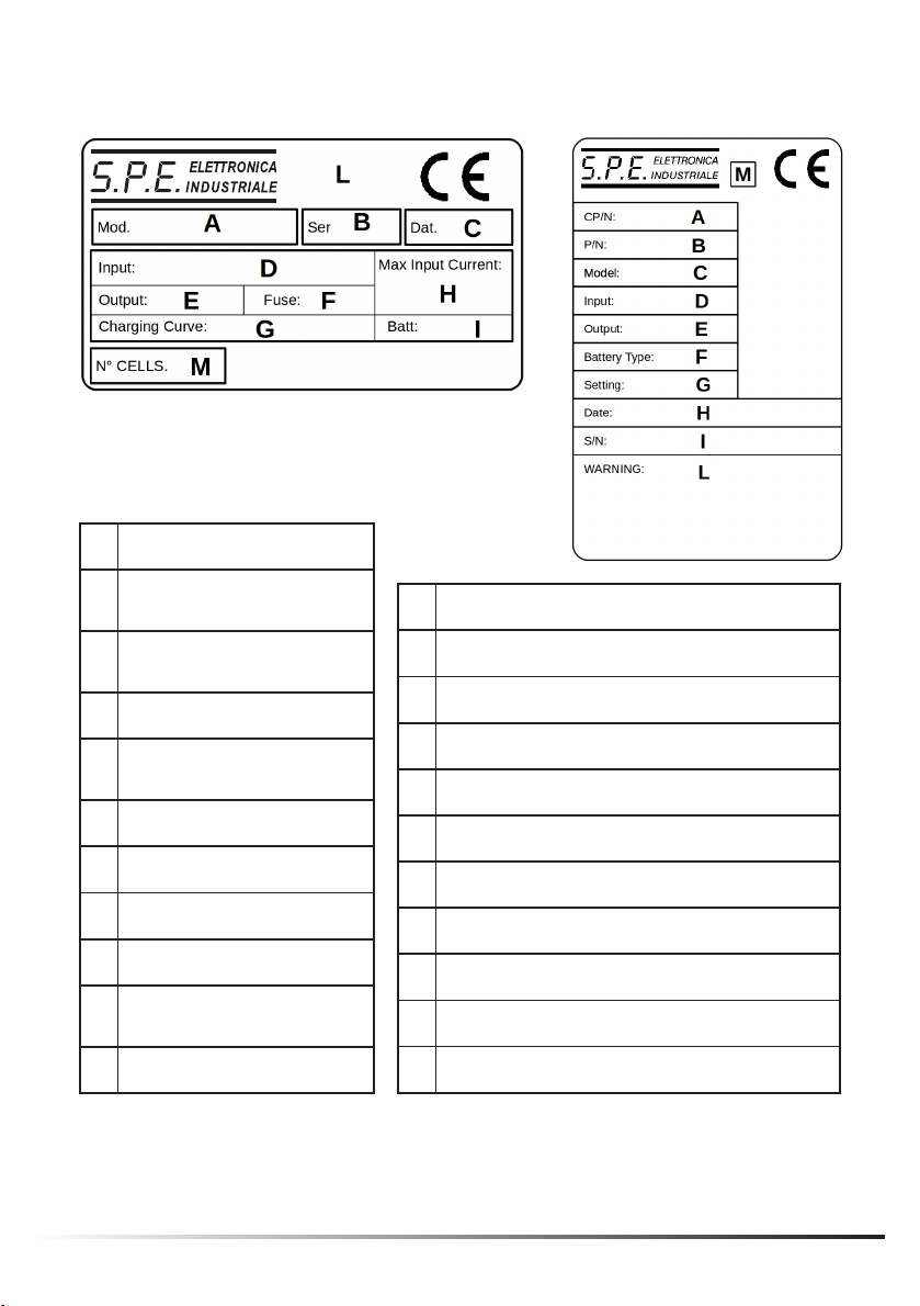
AMODEL
BBATTERY CHARGER SERIAL
NUMBER
CBATTERY CHARGER
MANUFACTURE DATE
DINPUT VOLTAGE
EOUTPUT VOLTAGE AND
CURRENT
FMAIN FUSE VALUE
GCHARGING CURVE
HMAINS ABSORPTION
IBATTERY CAPACITY RANGE
LPRODUCT CERTIFICATION
STAMPS
MNUMBER OF CELLS
BATTERY CHARGER IDENTIFICATION LABEL
ACUSTOMER PART NUMBER
BPART NUMBER
CMODEL
DINPUT VOLTAGE AND MAINS ABSORPTION
EOUTPUT VOLTAGE AND CURRENT
FBATTERY TYPE - NUMBER OF CELLS
GSETTING
HBATTERY CHARGER MANUFACTURE DATE
IBATTERY CHARGER SERIAL NUMBER
LWARNING
MPRODUCT CERTIFICATION STAMPS

7
Drill two or four holes into the wall
and fasten charger with 2 or 4
screws. Do not tighten the screws
all the way so that the charger can
hang on the screws.
WALL - MOUNT INSTALLATION
- -
ELECTRONIC BATTERY CHARGER - OPERATING MANUAL
CONTROL COMPONENTS
The display shows:
• Charging current (A)
• Battery voltage (U)
• Amp-Hours returned (C)
• Elapsed time (h)
• Active charge prole is displayed when button is pressed.
• To enter the charging parameter menu, see CHARGING SETTINGS.
OPERATION
Connect the AC power cable supplied with the battery charger to the charger.
Connect the battery to the charger with the correct polarity. Then, plug the AC
power cord into the wall receptacle.
The LCD display of the battery charger will now show, in sequence, information
related to the internal programming of the charger: the software version in-
stalled on the charger (e.g., Ver 009-008-001):
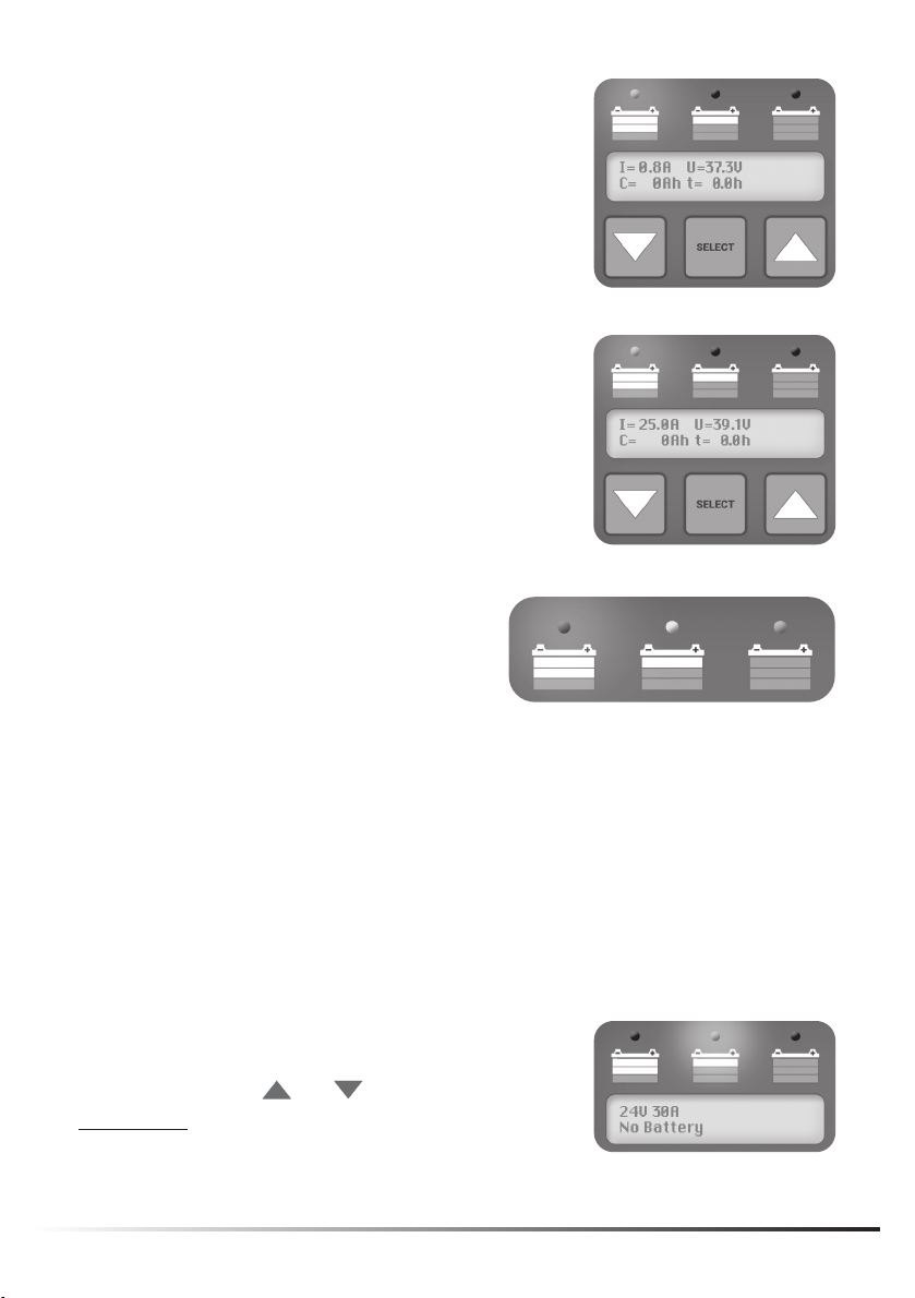
WALL
FLOOR
>
8
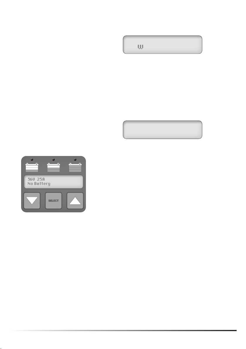
On the next screen, the LCD will display the parameters for:
• Battery voltage
• Charging current
• Number and type of charging curve
A test is conducted on the battery voltage to decide whether or not to start the
charging process.
If the battery is not connected to the charger, the display shows “No Battery”.
This message remains on the display, if the test is unsuccessful. The same
message is displayed in the case of:
• Reversed polarity
• Battery in short circuit
• Battery voltage is lower than 3V
If the battery test is still unsuccessful, the charger
continues to check the voltage on the battery
cables until it detects an acceptable condition.
9
If the test is successful, the battery charger
displays the battery voltage before starting the
charge, then displays the current value (A), the
voltage (V), Recharged Capacity (C) and Time
Elapsed from the start (t) Indicating that the
charging is in progress by turning on the red LED.
Shown below is an example of what the battery
charger display looks like after a successful start:
The progress of the charging cycle
is also indicated by three LEDs:
DL3 = display LED 3 (RED)
DL2 = display LED 2 (YELLOW)
DL1 = display LED 1 (GREEN) (RED) (YELLOW) (GREEN)
CHARGING SETTINGS
To set the charger in relation to the battery that needs to be charged, it is
necessary to carry out a few steps. Please note, only a service technician
should perform these functions!
The charging curve is set when the battery charger is not connected to the
battery.
To enter the programming menu, disconnect the
battery and once “No Battery” message appears,
press, and hold the and keys together for
10 seconds (the yellow DL2 LED ON indicates the
programming phase).

10
After selecting the parameter, you want
to change, press to activate
the option to edit the value (indicated by
the red DL3 LED that turns on) and use
the and keys to set the desired value.
You can now use the keys to scroll through the various parameters. The
following parameters can be changed: Type of curve, Voltage, and Current.
SELECT
Press again to conrm the set value
(the red DL3 LED will turn off).
SELECT
After setting the values, exit the setup menu
by selecting "Programming Save and Exit"
and press so that the display shows
" PARAMETERS SAVED " and the parameters
are saved in EEPROM.
SELECT
If the operator has entered the programming section and is still in it without
operation, the battery charger automatically goes back to the display showing the
charging status after about 30 seconds.

11
Where:
OFF = the LED is off
ON = the LED is steady
BLK = the LED is blinking
Note (*): The sequence of phases and relative messages varies according to the curve.
ERROR MESSAGES ON THE DISPLAY
In the event of anomalies, the following error codes may be displayed.
ERROR CODE PROBLEM SOLUTIONS
Srt:IB > IBmax The output current has
exceeded circuits the
nominal current value by
more than 10%.
Make sure there are no short cicuits on the battery
or the battery cables or there is an active load
on the battery that draws more current than the
charger can provide.
E01: Open Circuit The current suddenly went
to zero unexpectedly.
Check the connection of the clamps to the battery
and check the voltage of the battery elements to
make sure that there are no elements in an open
circuit condition. The charger starts again after 5
seconds.
E02: Temperature The internal thermal
sensor has detected high
temperature.
Use the charger in a well-ventilated area.
E03: Timer The safety timer of one
of the phases has been
activated.
Make sure that a suitable charging current has
been set for the battery capacity and that the
selected voltage corresponds to the voltage of
the battery. Also, make sure that there are no
elements in short circuit and that the battery is not
sulphated.
Start Auto-start execution OFF OFF OFF
F1 Phase 1: Initial charge at constant current ON OFF OFF
F2 Phase 2: Final charge at constant voltage ON OFF OFF
F3_I (*) Phase 3: Final charge at constant current OFF ON OFF
F3_U (*) Phase 3: Final charge at constant voltage OFF ON OFF
F4 Charging complete OFF OFF ON
LED MESSAGES DISPLAYED
Ref. Messages reported DL3 LED
(Red)
DL2 LED
(Yellow)
DL1 LED
(Green)

12
REF. MESSAGES REPORTED DL3 LED
(Red)
DL2 LED
(Yellow)
DL1 LED
(Green)
Phase timeout or too much
current
BLK OFF OFF
No Battery OFF BLK OFF
Inversion of polarity OFF BLK OFF
Battery in Short Circuit OFF BLK OFF
Incorrect Battery Voltage OFF BLK OFF
Over temperature error BLK OFF OFF
Corrupted charging prole BLK OFF OFF
Shown is an example of how an “E02: Temperature”
error will be displayed.

13

14
In case you need help with S.P.E.’s chargers you already have and use – like
technical assistance, repairs due to faults or replacements, contact:
Flight Systems Industrial Products (FSIP)
1015 HARRISBURG PIKE – CARLISLE, PA 17013
WEBSITE: www.shop.fsip.biz | PHONE: 1-800-333-1194
Or
Flight Systems Industrial Products (FSIP)
MIDWEST BRANCH
80 S. FAIRBANK STREET STE 7
ADDISON, IL 60101
1-800-804-5711
Always remember to provide the serial number and the manufacturing date of
the chargers.

15
NOTES/COMMENTS:
This manual suits for next models
1
Table of contents
Other S.P.E. Batteries Charger manuals


