True blue power TT43 Technical Document

INSTALLATION MANUAL AND
OPERATING INSTRUCTIONS
TT43 Battery Tester/Charger
True Blue Power® is a division of Mid-Continent Instrument Co., Inc.
Mid-Continent Instrument Co., Inc.
dba Mid-Continent Instruments and Avionics
9400 E. 34th Street N.
Wichita, KS 67226 Manual number 9017682
PH 800-821-1212 FX 316-630-0723 Rev D, August 22, 2014

True Blue Power, Wichita, KS
Rev D, August 22, 2014 2 of 11 Manual number 9017682
FORWARD
The True Blue Power TT43 was created specifically to test and charge Mid-Continent Instrument Company’s
4300 Series
Lifesaver
® and the True Blue Power TS420 Series battery packs. This manual provides
information intended for use by persons who are qualified to repair and service Mid-Continent Instrument
Company’s 4300-4xx Series Electric Attitude Gyro; the
LifeSaver
®. If further information is required, please
contact:
True Blue Power
c/o Mid-Continent Instrument Co., Inc.
Attn: Customer Service Dept.
9400 E. 34th St. N.
Wichita, KS 67226 USA
Phone 316-630-0101
Fax 316-630-0723
www.truebluepowerusa.com
www.mcico.com
We welcome your comments concerning this manual. Although every effort has been made to keep it free
of errors, some may occur. When reporting a specific problem, please describe it briefly and include the
manual part number, the paragraph/figure/table number, and the page number. Send your comments to:
True Blue Power
c/o Mid-Continent Instrument Co., Inc.
Attn: Technical Publications
9400 E. 34th St. N.
Wichita, KS 67226 USA
Phone 316-630-0101
Fax 316-630-0723
All products produced by Mid-Continent Instruments Co., Inc., including those identified as Mid-Continent
Instruments and Avionics or True Blue Power, are designed and manufactured in Wichita, Kansas, USA.
©Copyright 2014
Mid-Continent Instrument Co., Inc.

True Blue Power, Wichita, KS
Rev D, August 22, 2014 3 of 11 Manual number 9017682
REVISION HISTORY
ECO Rev. Date Detail
A 06/28/12 Initial release.
5812 B 08/14/12 Clarification of wording in annual test procedure section.
Clarification of wording in section five paragraph one.
6112 C 4/21/2014 Updated capacity test times for passing indication.
6235 D 8/22/2014 Updated Section 3 Test Procedure for clarification.

True Blue Power, Wichita, KS
Rev D, August 22, 2014 4 of 11 Manual number 9017682
Table of Contents
SECTION 1GENERAL DESCRIPTION 5
1.1INTRODUCTION 5
1.2FEATURES 5
SECTION 2OPERATION 6
2.1POWER 6
2.2CHARGING BATTERY 6
2.3TESTING BATTERY CAPACITY (DISCHARGE TIME): 7
SECTION 3MAINTENANCE 8
3.1TEST PROCEDURE FOR TT43 BATTERY TESTER/CHARGER 8
3.2RECYCLE INFORMATION 11

True Blue Power, Wichita, KS
Rev D, August 22, 2014 5 of 11 Manual number 9017682
Section 1 GENERAL DESCRIPTION
1.1 INTRODUCTION
The True Blue Power battery tester/charger is used for charging and testing the Mid-
Continent Instrument Company battery P/N’s 9015607 and 9016925, used primarily with the
4300-4xx Electric Attitude Indicator and TS420/TS420-1 Battery Backup Systems.
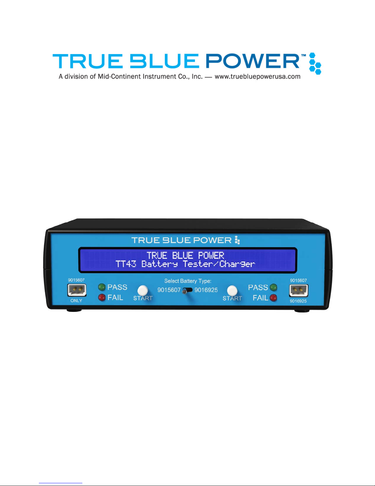
1.2 FEATURES
Figure 1
Battery Charger Control Panel
The following indicators are provided:
Digital Dot Matrix LCD Screen: Displays current process (i.e. charging/testing)
Pass: When illuminated indicates test of battery has tested good and battery does not need
to be replaced.
Fail: When illuminated indicates the battery has failed the test and it is recommended that
the battery be replaced.

True Blue Power, Wichita, KS
Rev D, August 22, 2014 6 of 11 Manual number 9017682
Section 2 OPERATION
2.1 Power
Plug the AC Adapter* (MCI P/N 9015904) into a standard wall outlet, and on the back of the test
box. When the switch on the back of the unit is in the “ON” position, the LCD screen will illuminate
and display start up screen followed by the battery charging screen. The battery tester/charger is
now ready to use.
* AC Adapter – Input: 90-264VAC, 50/60Hz, 30W. Output: 24VDC, 1.25A
2.2 Charging Battery
Note: Only charge or test Mid-Continent Instrument Company battery P/N’s 9015607 and
9016925 with the TT43 Battery Tester/Charger. Charging or testing other types of
batteries may damage the charger.
Plug the battery (P/N 9015607 or 9016925) into corresponding connector either labeled “9015607
ONLY” or you may plug the battery into the connector labeled with “9015607” or “9016925” with
the charger powered on. If you have chosen to plug the battery into the connector labeled
“9015607” or “9016925” then you will need to ensure that the center toggle switch is moved to the
appropriate position selecting which battery, either 9015607 or 9016925, to be charged or tested.
If the battery is not fully charged, the battery will immediately start charging with the screen
displaying “CHARGING”. Full charge may take up to 6 hours depending on battery type. The
system will charge either two 9015607 batteries simultaneously or one 9015607 and one 9016925
simultaneously.
When full charge is reached, the screen will indicate “FLOAT”. When this is indicated the charger is
now in float mode and will maintain the Battery in full charge condition.
IMPORTANT BATTERY INFORMATION
A) Do not charge a battery that shows signs of leakage or corrosion.
B) Do not charge a battery at extreme temperatures. It is recommended to charge the
Battery in a moderate temperature environment, avoiding extremes of either hot or
cold.
C) The Battery can be left on float charge indefinitely. Float charging will maintain the
best possible conditions to maintain the life of the battery.
D) The battery may be safely charged in any physical orientation.
E) If battery has charged for 9 hours or more but the LCD still indicates “Charging”,
unplug the battery and check battery voltage to see if it is 20.5VDC±0.5V. Plug battery
pack into the charger and wait for one minute, if the system indicates “FLOAT” and the
current is 25mADC or less, the battery is already fully charged. Proceed with Section 6
Testing Battery Capacity if this test has not been performed prior to the charge. (Use
this method to verify a full charge battery ONLY IF “FLOAT” is not indicated and
current is not less than 25mADC after charging for 9 or more hours.)

True Blue Power, Wichita, KS
Rev D, August 22, 2014 7 of 11 Manual number 9017682
2.3 Testing Battery Capacity (Discharge Time):
The process to test the battery life is a measure of the time to discharge a fully charged battery
into a load similar to that required to power a 4300-4XX gyro or the TS420/TS420-1 in emergency
modes. Follow the steps below to run the test:
A) Connect the battery taking care to select the correct battery if using the port labeled
“9015607 or 9016925”, and then allow at least 1 minute for stabilization of the battery
condition before pushing the “START” button.
B) Push the white “START” button and hold it in for at least 2 seconds then release. The battery
charger will then check to see if the battery is fully charged. If the battery is fully charged it
will begin the test. If the battery is not fully charged it will display “TESTING” along with
“CHARGING” to indicate a charge cycle has to finish before the test can be started. Once the
battery is fully charged the system will begin the test by applying a constant discharge load.
At this time below the “TESTING” indication on the screen a timer will start counting up.
When discharge is completed, the indication will become “TEST DONE”. If discharge time is
less than 60 minutes for 9015607 or less than 3 hours and 54 minutes for 9016925, the
system will illuminate the FAIL indicator and it is recommended that the battery be replaced.
If discharge time is 60 minutes or more for 9015607, the PASS indicator will light and the
system will continue discharging the battery. If discharge time is 3 hours and 54 minutes or
more for 9016925, the PASS indicator will light and the system will continue discharging the
battery.
C) The PASS or FAIL LEDs provide an indication based on a generic requirement of meeting
80% of the capacity of a new battery. However, for any particular installation, the power and
duration needed may represent a different capacity requirement. The actual requirement in
the installation must be considered before returning the battery to service. To evaluate the
battery’s capacity, consider the discharge time as provided by the battery charger. This
measures how long the battery under test can apply power to a 490 mA load. This value
serves as a point of reference for determining capacity in the specific installation.
D) After the battery discharge cycle is complete, the battery tester/charger will automatically
switch to fast charging mode and alternate between “CHARGING” and “TEST DONE”
screens.
E) Allow the battery to fully charge before use (See Section 5 Charging Battery).

True Blue Power, Wichita, KS
Rev D, August 22, 2014 8 of 11 Manual number 9017682
Section 3 MAINTENANCE
3.1 TEST PROCEDURE FOR TT43 BATTERY TESTER/CHARGER
Annual Verification of TT43 Tester/Charger performance is recommended.
Test Equipment:
Unit Under Test (UUT) (6430043-1)
AC Adapter (24VDC) (9015904)
Regulated DC Power Supply (0-30V, 1A)
DC Ammeter
DC Voltmeter
23 ohm power resistor rated greater than 20 watts
Test Procedure:
Note: “Long press” means press and hold the START button for 4 seconds then release.
1. Plug 24V AC adapter (9015904), into rear connector of UUT (6430043-1) and into wall outlet.
Power on UUT. The screen should display True Blue Power screen, then change to the main
battery screen.
2. UUT should display 20.5V ±0.2V for both ports.
3. Long press START on the 9015607 ONLY port. The red FAIL LED should turn on, and the
unit will alternate between a TEST DONE screen and the main battery screen. Long press
START again to clear. Repeat this step on 9015607/9016925 port. Power off UUT.
4. Connect test setup per Figure 1:
Figure 1: Test Connections
5. Turn on power supply and adjust voltage to 22.0V.
6. Power on UUT. Voltmeter should read 22.0V ±0.2V and ammeter should read -3mA ±1mA.
The UUT should display FLOAT.
AMMETER VOLTMETER
POWER SUPPLY
TT43 BATTERY CHARGER & TESTER
23Ω, 20W
+
+
+
+
+

True Blue Power, Wichita, KS
Rev D, August 22, 2014 9 of 11 Manual number 9017682
7. Reduce the voltage of the power supply until Voltmeter reads 20.0V, then long press START
on the 9015607 ONLY port. The UUT should read CHARGING. The ammeter should read
220mA or greater. The current displayed on screen should match the ammeter within
±10mA. Long press START on the 9015607 ONLY port. The voltage displayed on screen
should match the voltmeter within ±0.4V.
8. Increase the voltage of the power supply to 22.0V. The UUT should display FLOAT.
Voltmeter should read 22.0V ±0.4V, and ammeter should read -3mA ±1mA.
9. Move the test setup to the right side port labeled 9015607/9016925 with Battery Type switch
selecting the 9015607 battery. Adjust power supply to 22.0V.
10. Reduce the voltage of the power supply until Voltmeter reads 20.0V, then long press START
on the 9015607/9016925 port. The UUT should display CHARGING. The ammeter should
read 220mA or greater. The current on screen should match the ammeter within ±10mA.
Long press START on the 9015607/9016925 port. The voltage displayed on UUT should
match the voltmeter within ±0.4V.
11. Increase the voltage of the power supply to 22.0V. The UUT should display FLOAT.
Voltmeter should read 22.0V ±0.4V, and ammeter should read -3mA ±1mA.
12. Set Battery Type switch to the 9016925 position. Reduce the voltage of the power supply
until Voltmeter reads 20.0V. Long press START on the 9015607/9016925 port. The UUT
should display CHARGING. The ammeter should read 450mA or greater.
13. Long press START on the 9015607/9016925 port. Increase the power supply to 22.0V. The
UUT should read FLOAT. UUT voltage should display 22.0V ±0.4V and ammeter should read
-3 mA ±1 mA.
14. Turn off power supply and the UUT.
15. Connect test setup per Figure 2:
Figure 2: Test Connections
16. Turn on the power supply and the UUT and adjust the voltage to 22.0V.
AMMETER VOLTMETER
POWER SUPPLY
TT43 BATTERY CHARGER & TESTER
+
+
+
+
+

True Blue Power, Wichita, KS
Rev D, August 22, 2014 10 of 11 Manual number 9017682
17. Long press START on the 9015607 ONLY port. The screen should change to TESTING, and
the timer should start counting up.
18. The ammeter should read 246mA ±10mA. After approximately 5 to 10 seconds reduce the
voltage of the power supply to less than 15.5V. The UUT should display TEST DONE and
turn on the red FAIL LED.
19. Long press START on the 9015607 ONLY port to clear the UUT back to the main battery
screen. The red FAIL LED should go out.
20. Move the test setup to the right side port labeled 9015607/9016925 with Battery Type switch
selecting the 9015607 battery. Adjust power supply to 22.0V.
21. Long press START on the 9015607/ 9016925 port. The screen should change to TESTING,
and the timer should start counting up.
22. The ammeter should read 246mA ±10mA. After approximately 5 to 10 seconds reduce the
voltage of the power supply to less than 15.5V. The UUT should display TEST DONE and
illuminate the red FAIL LED.
23. Long press START on the 9015607/9016925 port to clear the UUT back to the main battery
screen. The red FAIL LED should go out.
24. Set the battery selection switch to 9016925 and adjust power supply to 22.0V.
25. Long press START on the 9015607/9016925 port. The UUT should display TESTING and the
timer should count up. The fan should begin to run immediately.
26. The ammeter should read 498mA ±10mA. After approximately 5 to 10 seconds reduce the
voltage of the power supply to less than 15.5V. The fan should stop running and the UUT
should display TEST DONE with the red “FAIL” LED on.
27. Long press START on the 9015607/9016925 port to clear the UUT back to the main battery
screen. The red FAIL LED should go out.
28. Test is complete. Power off and unplug UUT from Test Set.

True Blue Power, Wichita, KS
Rev D, August 22, 2014 11 of 11 Manual number 9017682
3.2 RECYCLE INFORMATION
A) Store spent batteries under cover and on an impervious surface.
B) Keep spent batteries from freezing to avoid cracking their cases.
C) DO NOT dispose of spent batteries in the trash or any landfill. The battery contains lead and
MUST be routed to a recycling center.
D) Choose a reputable battery recycler. Call 1-800-8BATTERY for a location near you or visit
www.rbrc.org.
Table of contents
Other True blue power Batteries Charger manuals

True blue power
True blue power TWC15 Series User manual

True blue power
True blue power TA202 Series Technical Document

True blue power
True blue power TA102 Technical Document

True blue power
True blue power TA102 Technical Document

True blue power
True blue power TA360 Series Technical Document

True blue power
True blue power TA202 Series Technical Document