S.R.Smith poolLUX Plus pLX-PL60 User manual
poolLUX®Plus
pLX-PL60 & pLX-PL100
Installation Instructions
Read all instructions before attempting to perform installation work
Type 3R Rainproof Enclosure
FOR USE WITH POOL AND SPA PRODUCTS
5005508
ETL LISTED
Conforms to UL STD 379;
Certied to CSA STD C22.2 #218.1
79-15264-00 REV6/18

2

3
Contents
IMPORTANT SAFETY INFORMATION ................................4
RF Exposure Statement .................................................5
IC Statement.............................................................5
FCC WARNING .........................................................5
Electrical Ratings ........................................................6
Recommended Tools and Supplies ......................................6
INSTALLATION INSTRUCTIONS.......................................7
Enclosure mounting .....................................................7
Input / Supply Line Voltage ..............................................9
Output Wiring for Lights and Light Sources........................... 10
OPERATING INSTRUCTIONS........................................ 12
Manual Rocker Switch Operation ..................................... 12
Wireless Remote Operation........................................... 13
WIRING DIAGRAM ................................................... 14
REPLACEMENT PARTS ............................................... 15

4
IMPORTANT SAFETY INFORMATION
CAUTION: POWER AND SIGNAL OUTPUT CONDUITS MUST BE NON-METALLIC
ATTENTION: CONDUITS POUR PUISSANCE DE SORTIE ET SORTIE SIGNAL DOIT ETRE NON METALLIQUE
ELECTRICAL SHOCK HAZARD – SWITCH DOES NOT TURN OFF INPUT POWER.
Failure to disconnect input power before servicing can lead to serious injury, or death.
Disconnect input power before servicing.
Replace all parts and panels before reconnecting power and operating
DANGER – FAILURE TO FOLLOW THESE WARNINGS, INSTRUCTIONS, AND THE
OWNER’S MANUAL MAY RESULT IN SERIOUS INJURY OR DEATH.
Basic safety precautions shall be observed when installing and operating the poolLUX®Plus
(p/n pLX-PL60/PL100) and other associated equipment:
1. A qualied electrician must install the poolLUX® Plus (p/n pLX-PL60/PL100) in accordance
with the requirements of NEC ANSI/NFPA 70 and Article 680.
2. The poolLUX® Plus (p/n pLX-PL60/PL100) must be mounted on a at vertical surface. The
unit must be a minimum of 4 inches above the ground level, pool deck, or higher than 8 inches
above the maximum pool water level, whichever provides greatest elevation. The unit must be
positioned a minimum of 4 feet (1.2 m) away from the inside wall of the pool, unless separated
from the pool by a solid fence, wall, or other permanent barrier.
3. CAUTION: THE EQUIPMENT AND CONTROLS SHALL BE LOCATED NOT LESS THAN
1 M HORIZONTALLY FROM THE SPA OR HOT TUB.
4. ATTENTION: MAINTENIR UNE DISTANCE MINIMALE, MESURÉE DANS UN PLAN
HORIZONTAL, DE 1 M ENTRE LA CUVE DE RELAXATION ET LES APPAREILS ET
COMMANDES.
5. ONLY USE COPPER CONDUCTORS.
6. Do not exceed the maximum electrical ratings of the poolLUX® Plus (p/n pLX-PL60/PL100)
components (indicated on page 6), wiring devices, and current carrying capacity of the
conductors.
7. poolLUX® Plus (p/n pLX-PL60/PL100) is intended to be used with low voltage underwater
luminaires that comply with Article 680 of the National Electrical Code and does not require
bonding due to their polymeric or isolated application design.
8. This device should never operate equipment that could cause property damage, bodily injury,
or death should it be activated unexpectedly.
9. Use with branch circuit breakers with 15 amperes or less.
10. This device must be used with an approved ground-fault circuit interrupter (GFCI).
11. Use rain-tight or wet location hubs that comply with the requirements in the standard (UL514b)
for conduit, tubing, and cable ttings only.
12. The conduit hub is to be connected to the power input conduit before the hub is connected to
the enclosure.
13. Never allow children to operate the pLX-Plus unit unsupervised.

5
RF Exposure Statement
IC Statement
FCC WARNING
To maintain compliance with FCC’s RF Exposure guidelines, this equipment should be installed
and operated with minimum distance of 20cm between the radiator and your body. Only use the
supplied antenna.
This device complies with Industry Canada license-exempt RSS standard(s). Operation is subject to
the following two conditions:
(1) this device may not cause interference, and (2) this device must accept any interference,
including interference that may cause undesired operation of the device.
Le présentappareilestconforme aux CNR d’Industrie Canada applicables aux appareils radio
exempts de licence. L’exploitationestautorisée aux deux conditions suivantes:
(1) l’appareil ne doit pas produire de brouillage, et (2) l’utilisateur de l’appareildoit accepter
tout brouillageradioélectriquesubi, mêmesi le brouillageest susceptible d’encompromettre le
fonctionnement.
1. This device complies with Part 15 of the FCC Rules. Operation is subject to the following two
conditions: (1) this device may not cause harmful interference, and (2) this device must accept
any interference received, including interference that may cause undesired operation.
2. Changes or modications not expressly approved by S.R.Smith, LLC will void the user’s
authority to operate the equipment.
NOTE: This equipment has been tested and found to comply with the limits for a Class B digital
device, pursuant to Part 15 of the FCC Rules. These limits are designed to provide reasonable
protection against harmful interference in a residential installation. This equipment generates,
uses and can radiate radio frequency energy and, if not installed and used in accordance with
the instructions, may cause harmful interference to radio communications. However, there is no
guarantee that interference will not occur in a particular installation. If this equipment causes
harmful interference to radio or television reception, which can be determined by turning the
equipment off and on, the user is encouraged to try to correct the interference by one or more of
the following measures:
• Reorient or relocate the receiving antenna.
• Increase the separation between the equipment and receiver.
• Connect the equipment on a different circuit than that of the receiver.
• Consult the dealer or an experienced Radio and Television Technician for help.

6
Electrical Ratings
Do not exceed the maximum electrical output rating of each unit listed below.
Model Input Output
pLX-PL60 120 VAC, 60 Hz, 0.6A max 12-13 VAC, 60 Watt max
pLX-PL100 120 VAC, 60 Hz, 1.0A max 12-13 VAC, 100 Watt max
Use a 15 Amp, 120VAC GFCI Circuit Breaker for input power.
ELECTRICAL PROTECTION MEASURES
Dual Internal Fuses
1) Self-Resetting Thermal Fuse: This fuse keeps the unit from overheating in instances where a
load in excess of the transformer’s capacity is present for an extended period of time. Once normal
operating temperatures return, the unit will reset and operation will continue.
2) Current Fuse: This fuse shuts down the low-voltage output of the transformer during an
abnormal electrical condition (i.e. “Short”). This fuse has a higher trigger threshold than the
Replaceable Current Fuse and serves as a fail-safe for the Replaceable Current Fuse to ensure that
an abnormal electrical condition does not lead to an unsafe operating condition.
Replaceable Current Fuse*
This eld replaceable part is the primary protection against abnormal electrical conditions. This fuse has a
lower trigger threshold than the Internal Current Fuse and is designed to blow rst in the event of a short
and helps reduce whole transformer replacement due to eld induced shorts (“sparking wires”), as well
as, other abnormal electrical conditions. In addition, this fuse is fast acting which helps protect against
abnormal electrical conditions that can lead to an unsafe operating condition.
*ONLY USE SR SMITH REPLACEMENT FUSES: pLX-PL60 (Part Number: 36-15017-00) /
pLX-PL100 (Part Number: 36-15018-00)
Recommended Tools and Supplies
1. Circular hole saw for installation of 3/4" and or 1" non-metallic conduit depending on
installation requirements. Do not use spade bits for opening the conduit knockouts.
2. Application appropriate and approved ‘rain-tight’ or ‘wet location’ conduit hubs.
3. Additional duct seal may be required for three or more conduit installations.
* Note: Every installation will have at least two conduits - one for input power and one for
output power. Most installations will likely have several output power conduits.
4. Slotted screwdriver, size #2
5. Phillips screwdriver, size #2
6. Drill
7. #10 Screws appropriate for installing the product onto a wall (installer supplied)
* Note: It is recommended to hand tighten all screw terminals and screw fasteners inside the
enclosure and front cover until snug and secure. Be sure not to overtighten as permanent
damage may occur.
7
INSTALLATION INSTRUCTIONS
WARNING
• TURN OFF INCOMING POWER BEFORE SERVICING EQUIPMENT.
• ALL INSTALLATION AND MAINTENANCE WORK MUST BE PERFORMED BY A
QUALIFIED ELECTRICIAN.
• GFCI BREAKER MUST BE USED TO CONNECT (p/n pLX-PL60/PL100) TO INPUT POWER.
• VERIFY ALL ELECTRICAL RATINGS BEFORE INSTALLATION IS COMPLETE.
• FOLLOW PROPER WIRING PRACTICES IN ACCORDANCE WITH ALL NATIONAL AND
LOCAL REGULATORY REQUIREMENTS.
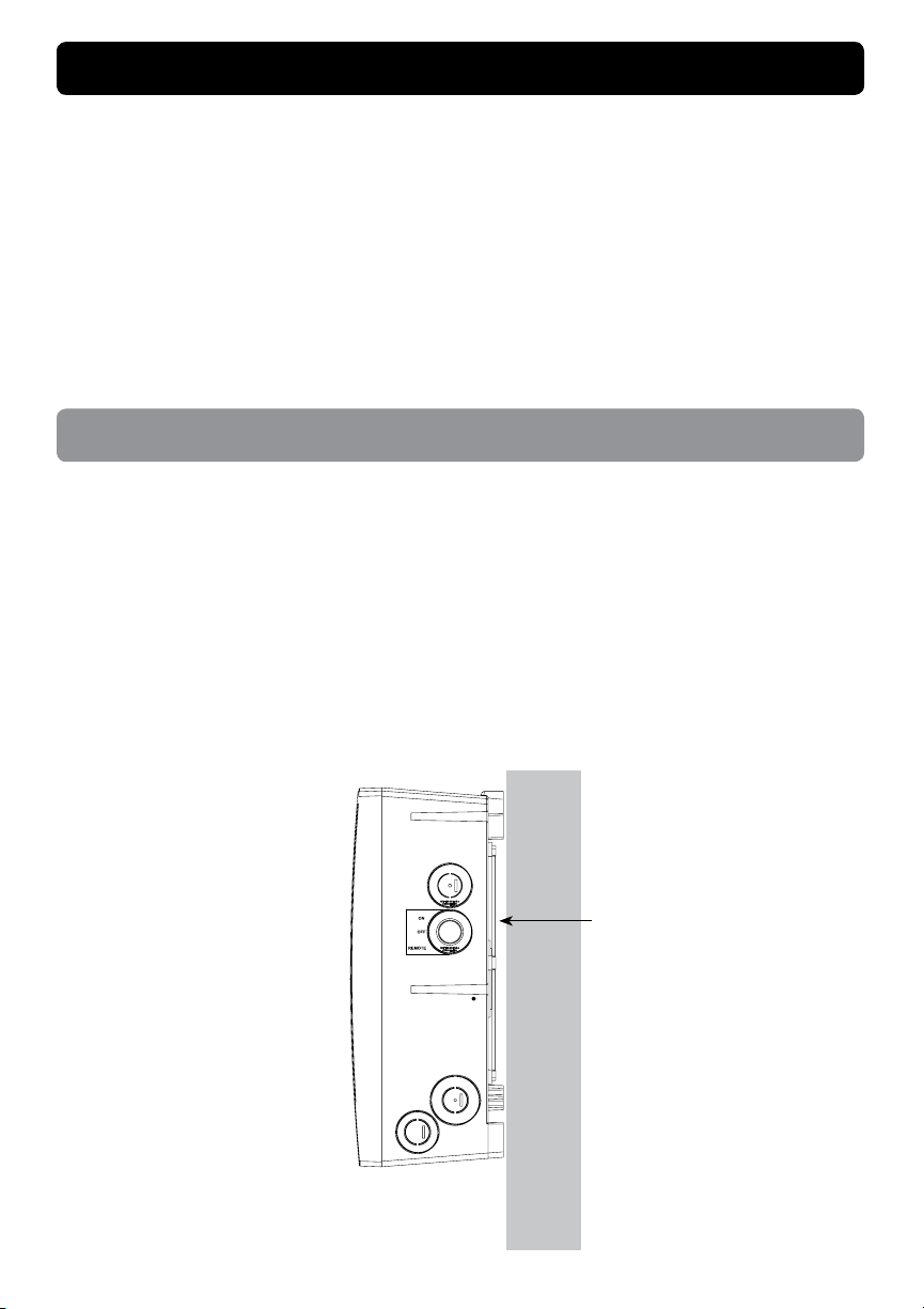
Enclosure mounting
1. Locate the poolLUX® Plus (p/n pLX-PL60/PL100) in an appropriate area that meets the
following requirements:
a. Must be mounted on a at vertical surface.
b. Must be a minimum of 4 inches above the ground level, pool deck, or higher than 8 inches
above the maximum pool water level, whichever provides greatest elevation.
c. Must be positioned a minimum of 4 feet (1.2 m) from the inside wall of the pool unless
separated from the pool by a solid fence, wall, or other permanent barrier.
For the unit to be adequately air cooled, allow a minimum gap of 9/32" (7.2mm) between the wall
and the back surface of the unit. The stand-off mounting tabs will make contact with the wall.
WALL
Minimum Gap of 9/32" or 7.2mm
8
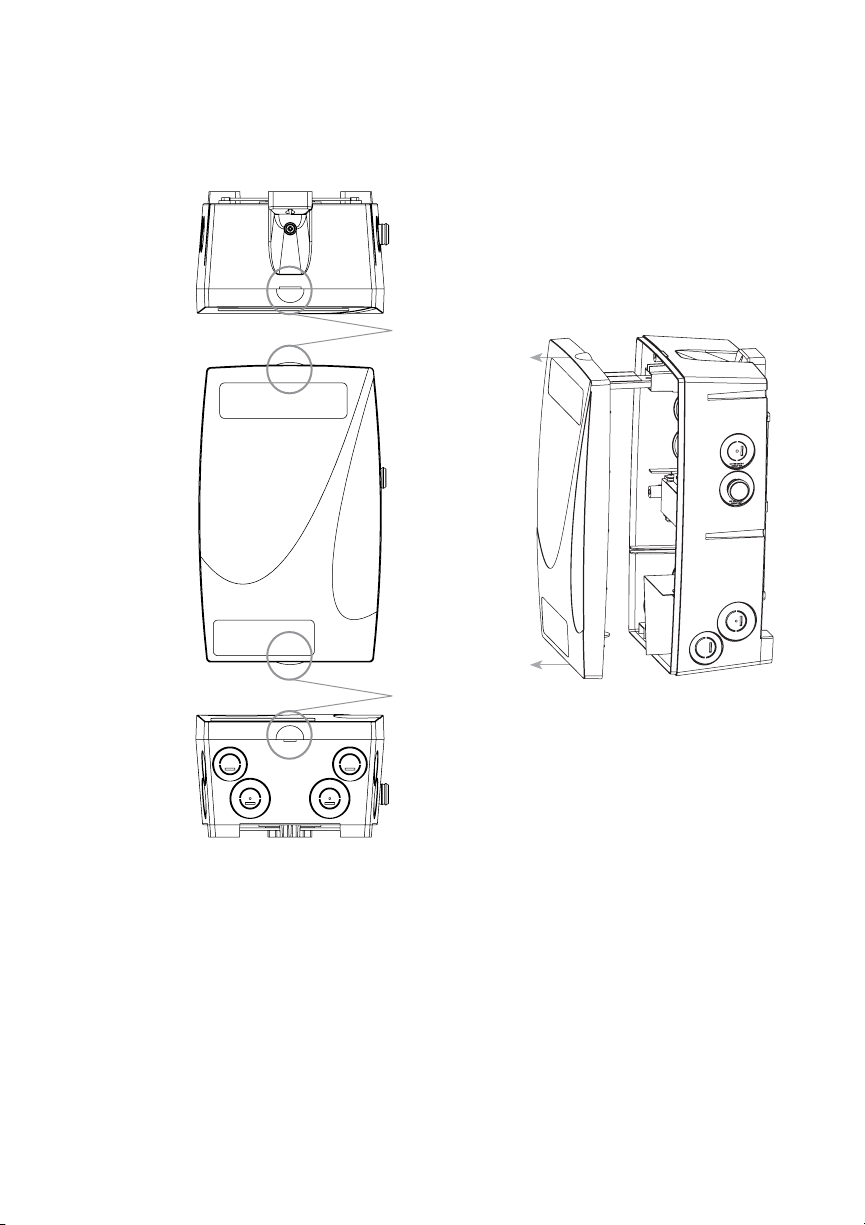
2. By hand, open the enclosure by pulling the front cover off evenly by the top and bottom tabs.
Do not angle or ‘hinge’ the cover when removing or damage may occur. If you cannot open
the enclosure by hand, use a at blade screwdriver to twist open the nger tabs of the cover
at the top and bottom of the unit.
3. Securely install a wall material appropriate #10 screw (Installer Supplied) into the location
where the unit will be installed. The screw head must be 1 1/8” away from the wall to allow the
unit to be mounted correctly.
4. Place the mounting tab of the poolLUX® Plus (p/n pLX-PL60/PL100) over the #10 screw and
let it hang in place. Level the unit and mark the remaining 2 mounting screw locations on the
wall. Use 2 more material appropriate #10 screws (Installer Supplied) to secure the unit to the
wall through the mounting holes on the back of the unit. Once the lower two screws are secure,
tighten the top screw to securely hold the upper portion of the enclosure in place.
Top View
Enclosure
Front View
Enclosure
Side View Enclosure
Remove front cover by
evenly pulling the top
and bottom tabs
Bottom View
Enclosure
Top Tab
Bottom Tab

9
3a3b
1a
2a
1b
2b
Input / Supply Line Voltage
1. Remove the metal input voltage isolation barrier by unscrewing the mounting screw. Once the
securing screw is removed, the isolation cover will pull straight out to allow easier access to the
conduit knockout locations.
3a3b
1a
2a
1b
2b
Metal Input Voltage Isolation
Barrier Mounting Screw
Locations of Input
Power Knockouts
Locations of Output
Power Knockouts
*Note: Once all conduits are connected, replace the metal input voltage isolation barrier and
mounting screw. Tighten until the mounting screw is secure.
2. Bring the supply power conduit to one of the four, lower right input power conduit knockout
locations that terminate ‘inside’ the isolation barrier. No output connections are allowed
through these knockout locations.
*Note: The wiring of the input and output power are required to use separate conduits
and must not share an individual conduit. No conduit should contain both input and output
power wiring.
3. Using a hole saw, open the knockouts for the size of the conduit (¾" or 1") being installed.
ON
OFF
REMOTE

10
4. Attach an approved ‘rain-tight’ or ‘wet location’ hub to the conduit. After the hub is attached
to the conduit, attach the hub to the enclosure.
5. Connect the GFCI protected, 15A max, supply voltage line to the right side of the terminal
block. Strip ¼” of insulation and then connect the wires to the marked terminals and tighten
securely.
120V Hot GFCI Load to terminal marked: H
120V Neutral GFCI Load to terminal marked: N
Electrical System Ground to terminal marked: GND
6. Replace and secure the metal input voltage isolation barrier and verify that the input wiring
screw terminals are secure.
12VAC
13VAC
POWER INPUT
NEUTRAL
POWER INPUT
POWER INPUT
GROUND
COM
GROUND
GND NH
Input Wiring Locations
Output Wiring for Lights and Light Sources
1. The combined load of all lights connected to the poolLUX®Plus must not exceed the following:
• pLX-PL60 = 60 watts max
• pLX-PL100 = 100 watts max
2. The enclosure provides four (4) output conduit locations. If additional conduit terminations
are required, an approved junction box may be used as a termination point and multiple output
cables may be run through a single feeder conduit to the poolLUX® Plus.
3a3b
1a
2a
1b
2b
Locations of Input
Power Knockouts
Locations of Output
Power Knockouts
GND12V L/V 13V
Fuse Holder
This manual suits for next models
14
Table of contents
Popular Swimming Pool Lighting manuals by other brands

BEGA
BEGA 88 913 Instructions for use

Wibre
Wibre 4.0171 installation manual

Pentair
Pentair INTELLIBRITE 5G Installation and user guide

Pentair Pool Products
Pentair Pool Products FIBERworks 20100100 owner's manual

GRE
GRE LAGP8 Installation and maintenance manual

CONCORD
CONCORD PATHE G/R2-S2 quick start guide


