SafeGait SG360 User manual

SafeGait™ 360° Balance and Mobility Trainer
Service manual
SG360-ISM-004 Rev. F

SG360-ISM-004 | REV F
1
Table of Contents
General Warnings …………….……………………….……..………………………………………………………………………………..2
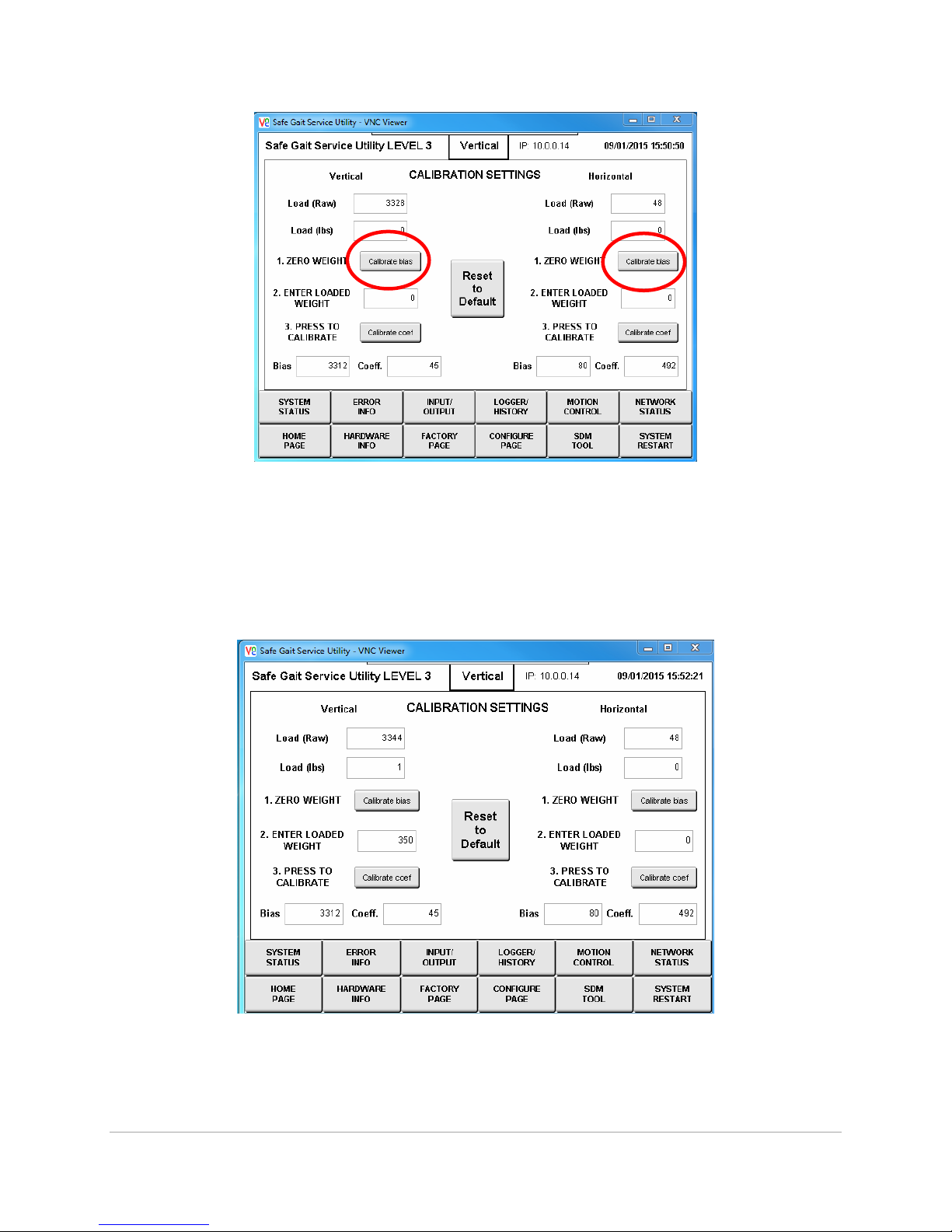
Load Cell Recalibration................................................................................................................................. 3
Logging out of the SafeGait application kiosk .......................................................................................... 3
VNC service interface .............................................................................................................................. 4
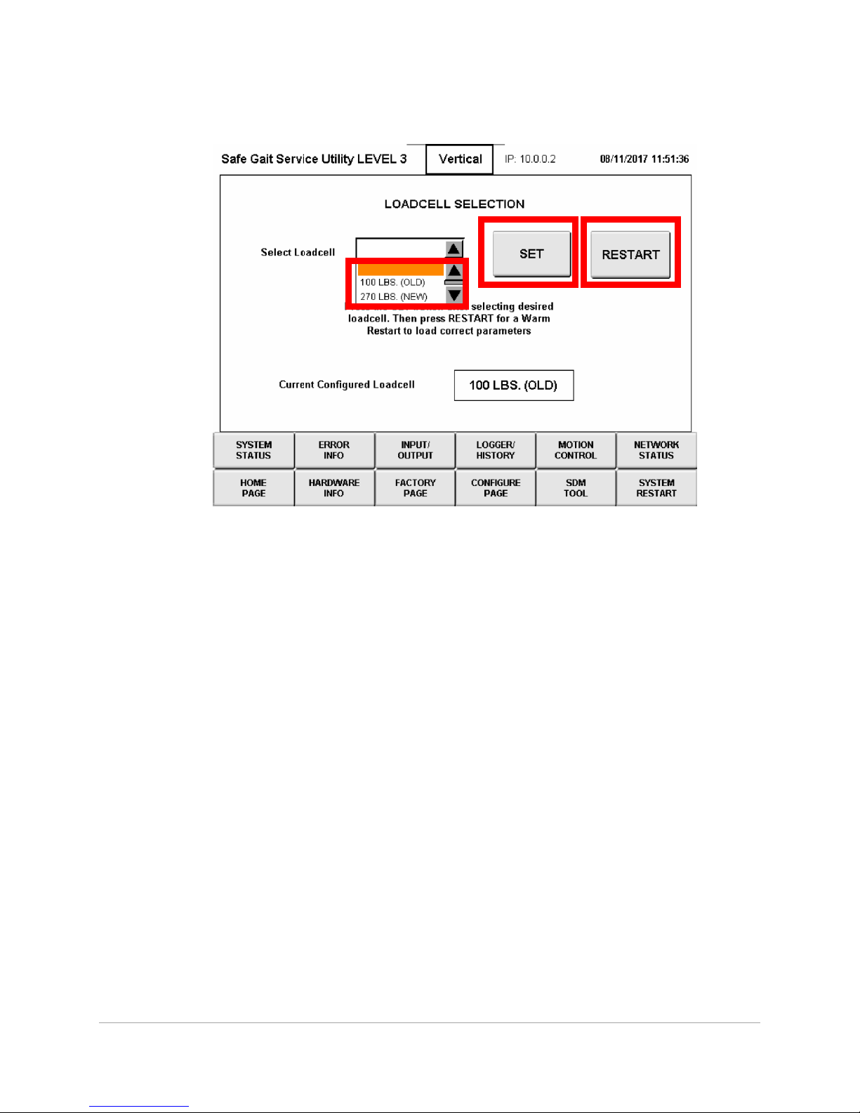
Selecting load cell .................................................................................................................................... 8
HMI battery change procedure ................................................................................................................. 10
Opening the SafeGait covers................................................................................................................. 11
Procedure for battery change .............................................................................................................. 13
Replace Trolley Wheel Block Assembly .................................................................................................... 14
Replace Strap Assembly ............................................................................................................................ 15
Setting Rotary limit switch ..................................................................................................................... 24
Actuator Check out Test ............................................................................................................................ 26
SafeGait Wiring Diagrams ......................................................................................................................... 27
Facility Panel Wiring Diagrams ................................................................................................................. 42
WIFI Ping Test ............................................................................................................................................ 47
Power Panel Green LED Replacement ...................................................................................................... 49
Version 4.0.1 Software install ................................................................................................................... 51
Data backup ............................................................................................................................................ 52
CF Card update to Version 3.1.1 ............................................................................................................. 53
Kiosk Laptop/Tablet (V4.0.1) Windows 10.............................................................................................. 56
Kiosk Laptop/Tablet (V4.0.1) Windows 8................................................................................................ 62
Remote/Handheld Android 5.1............................................................................................................... 68
Remote/Handheld Android 6.1............................................................................................................... 69
Router upgrade ....................................................................................................................................... 70
WIFI adaptor upgrade ............................................................................................................................. 73
NAS upgrade ........................................................................................................................................... 75
Linear Bearing Replacement ..................................................................................................................... 78
4 Pole hanger replacement ...................................................................................................................... 82
Conductor shoe replacement .................................................................................................................. 83

SG360-ISM-004 | REV F
2
General Warnings:
WARNING: Arc flash is possible
during power-up after service if the
conductor shoes are not installed in
the correct conductor bars.
DANGER: the SafeGait 360® system
operates at 480 VOLTS. Always use
caution and wear appropriate PPE
(Personal Protective Equipment)
when working near Actuator or Rail
when power is applied. Failure to
comply may result in injury or
death!
WARNING: Pinch points areas
include the trolley wheels on the
rail and the Actuator end stops (if
installed).
WARNING: when servicing the
Actuator after operation, the
horizontal and vertical drive motors
may be hot.

SG360-ISM-004 | REV F
3
Load Cell Recalibration:
1. From the kiosk computer, exit out of the SafeGait Application by pressing (Ctrl +Shift +Esc).
This will a launch the Task Manager
2. Click on the file menu and select Run new task.
3. In the Create new task window in the open box type explorer.exe and press ok.

SG360-ISM-004 | REV F
4
4. Depress the windows key. This will launch the blue widow start screen at the top. Click on the
therapist user and a pop up window will appear. Select Admin user.
5. Enter admin password for kiosk. Reference KeePass for site specific password.
6. Open VNC viewer on desktop.
7. Connect to the service interface using VNC at IP address 10.0.0.2:5900.
10.0.0.2:5900

SG360-ISM-004 | REV F
5
8. When prompted for a password enter 123.
9. Log in using Service Code 8 followed by the check key.

SG360-ISM-004 | REV F
6
10. Click on the FACTORY PAGE button.
11. To calibrate the load cell, click on the LOAD CELL CALIBRATION button.

SG360-ISM-004 | REV F
7
12. Remove the spreader bar from the strap such that no weight is suspended.
13. Press the Calibrate Bias button in the VERTICAL axis (left side). The vertical Bias number should
change to the Load (Raw) value and the load (in lbs) should be 0 (zero).
14. Re-attach the spreader bar and let it hang. Wait for any swinging to cease.
15. Press the Calibrate Bias button in the HORIZONTAL axis (right side). The horizontal Bias number
should change to the Load (Raw) value and the load (in lbs) should be 0 (zero)

SG360-ISM-004 | REV F
8
16. When the recalibration is complete, the vertical load cell should display a load of 1-2 lbs. and the
horizontal load cell should display a load of zero. Press the HOME PAGE button to complete the
recalibration.
Selecting load cell
1. Login to VNC
2. Click on Factory page

SG360-ISM-004 | REV F
9
3. Click on the load cell selection Button
4. From select load cell drop down select the load cell that is in the strap management
5. Then press the set button
6. Followed by the reset button
7. Wait for the warm reset to occur then you can login to the VNC and verify the correct load cell
has been selected

SG360-ISM-004 | REV F
10
HMI battery change procedure:
The lithium battery buffers the internal real-time clock (RTC) and CMOS data.
Information:
•The product design allows the battery to be changed with the B&R device switched either
on or off. In some countries, safety regulations do not allow batteries to be changed
while the module is switched on.
•Any BIOS settings that have been made will remain when the battery is changed with the
power turned off (stored in nonvolatile EEPROM). The date and time must be reset later
since this data is lost when the battery is changed.
•The battery should only be replaced by qualified personnel
Warning!
The battery is only permitted to be replaced by a Renata CR2477N battery. The use of
another battery may present a risk of fire or explosion.
The battery may explode if handled improperly. Do not recharge, disassemble or
dispose of in fire.

SG360-ISM-004 | REV F
11
Opening the Covers:
1. Power down the unit and follow all lockout tag out procedures.
2. Using an insulated screwdriver, depress latching tab on inside of covers.
DANGER: Power system down and lock out power panel prior to opening the covers.
Failure to comply may result in injury or death!

SG360-ISM-004 | REV F
12
3. While holding in on latching tab press up on covers to release.
4. Disengaged the latching pins in on either side of the HMI allow HMI to swing down.
Note: starting with Actuator serial number 9101200C-0001, the latching pins are obsolete. Loosen
and remove the lower screw and nut on both sides of the bracket to allow the HMI to swing down.
5. Locate battery on backside of HMI.

SG360-ISM-004 | REV F
13
Battery Replacement Procedure
The battery should not be held by its edges. Insulated tweezers may also be used to insert the
battery
•To make the next battery replacement easier, be sure the removal strip is in place when inserting the
battery.
Correct
Incorrect
•
Insert the new battery with the correct polarity.
Figure 164: Insert battery
Disconnect the power supply to the B&R Industrial PC.
Touch the housing or ground connection in order to discharge any electrostatic charge from your body.
Remove the cover from the battery compartment and carefully pull out the battery using the removal strip.
Battery cover
Removal strip
Figure 162: Removing the battery

SG360-ISM-004 | REV F
14
Replace Trolley Wheel Block Assembly:
DANGER: Power system down and lock out power panel prior to replacing Trolley Wheel Block
Assembly. Failure to comply may result in injury or death!

SG360-ISM-004 | REV F
15
Replace Strap Assembly:
1. Login to the windows Admin using the provided password.
2. On the desktop open VNC
3. In VNC server line enter 10.0.0.2 if not already displayed in box then click connect
4. If a warning pops up about unencrypted connection click on the continue button if not skip to
step 5

SG360-ISM-004 | REV F
16
5. When prompted for a password enter 123
6. Login screen will pop up click on the service code and a keyboard will pop up.

SG360-ISM-004 | REV F
17
7. Click on service code box enter service code 8 followed by the check mark.
8. Then hit the enter key to login to the HMI

SG360-ISM-004 | REV F
18
9. On the login screen click on the input/output button
10. On the input/output page push the force button and then turn E-stop 1 and E-stop 2 Back on.
11. Then hit the Force button once again

SG360-ISM-004 | REV F
19
12. Click on the Motion control button and then enable the vertical motor
13. Using the Velocity NEG to pay out all of the strap from the unit using VNC client.
a. NOTE: When the spreader bar touches the floor, you will need to apply pressure to strap
to insure it continues to spool off the drum.
b. Use a pair of scissors to cut the strap as close as possible to the Actuator cover. Discard.
14. Power unit down and lock out tag out power panel.
15. Open covers using instructions listed in this manual.
16. NOTE: If installing a STRAP ASSEMBLY with a serial number of 0917001 or higher, removal and
replacement of the Strap Management Assembly is not necessary. Skip to step 22.
17. NOTE: starting with Actuator serial number 9101200C-0001, unplug the load cells from the
extension cables located on the vertical bracket.
18. Unplug load cells from signal conditioning PCB
a. You can remove the side cover to allow more access to the connectors
Table of contents