Saferoads HV2 Safety Barrier User manual

W www.saferoads.com.au
T +61 3 5945 6600
USA Version 1.
4
March 2019
Page 1
Contents
Preface .............................................................................................................................................................................. 2
Introduction ...................................................................................................................................................................... 2
Applications ....................................................................................................................................................................... 2
Limitations......................................................................................................................................................................... 3
Testing ............................................................................................................................................................................... 3
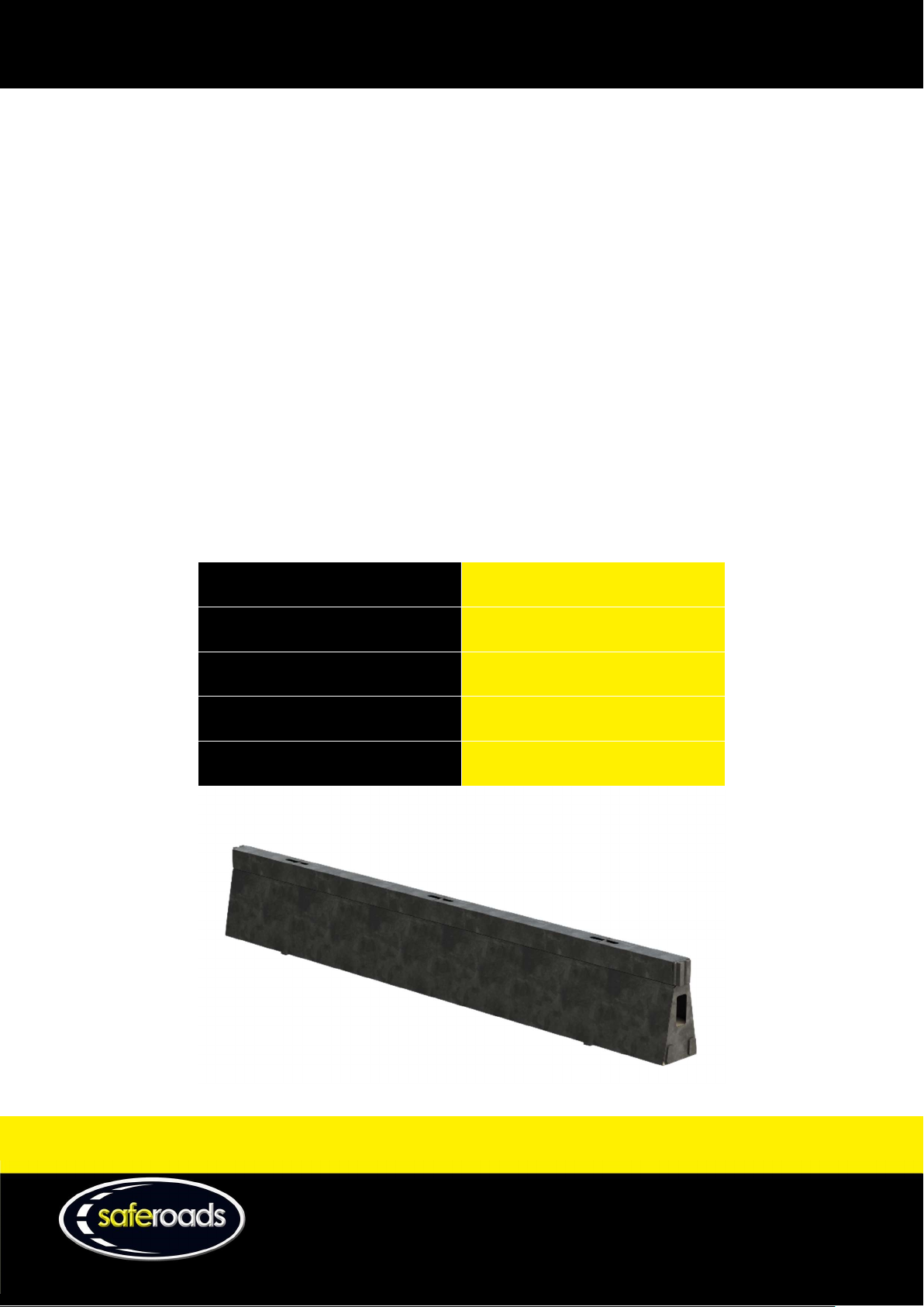
Barrier Segments ............................................................................................................................................................... 3
Minimum Deployment ...................................................................................................................................................... 6
End Treatment .................................................................................................................................................................. 6
Length of Need .................................................................................................................................................................. 6
Beginning of Length of Need......................................................................................................................................... 6
End of Length of Need .................................................................................................................................................. 7
System Deflection ............................................................................................................................................................. 8
Working Width .................................................................................................................................................................. 9
Site Considerations ......................................................................................................................................................... 10
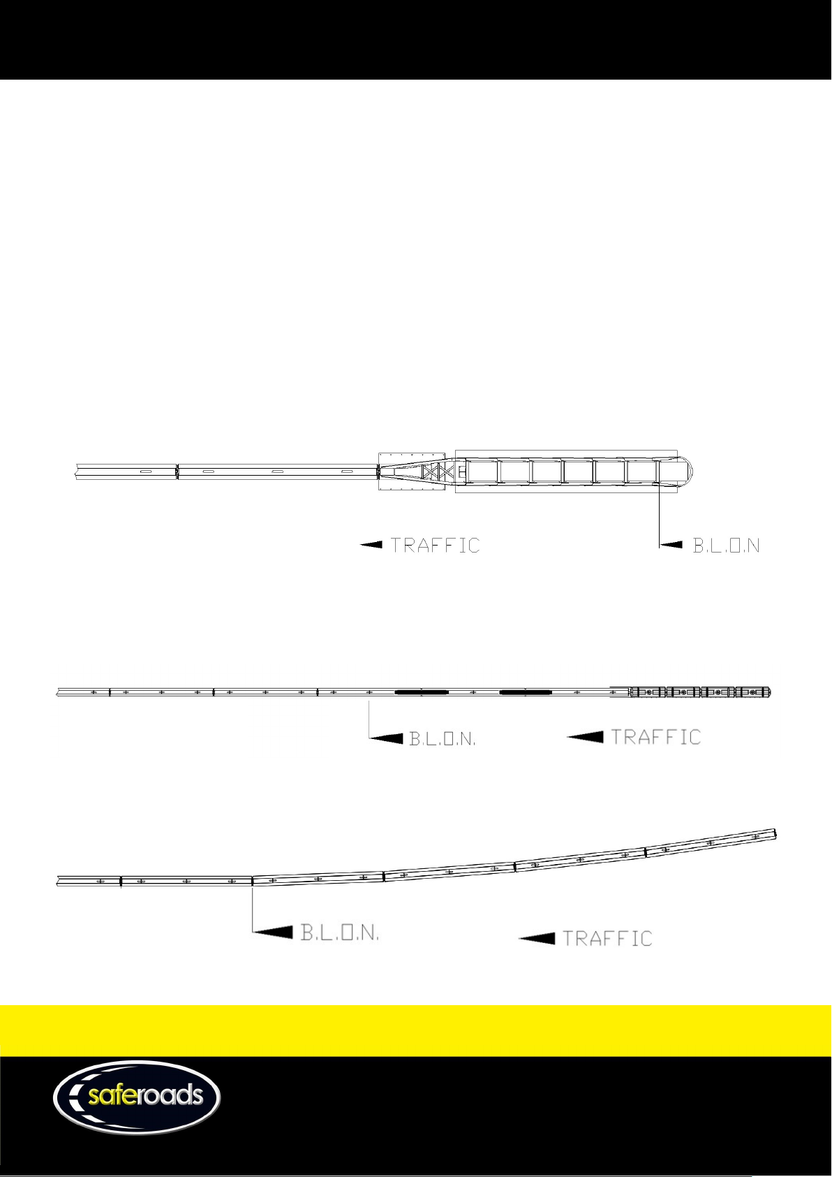
Barrier Deployment ........................................................................................................................................................ 10
QuadGuard Crash Cushion Deployment ......................................................................................................................... 11
SLED Crash Cushion Deployment .................................................................................................................................... 12
Maintenance and Repair ................................................................................................................................................. 13
Safe Work Method Statement ........................................................................................................................................ 14

W www.saferoads.com.au
T +61 3 5945 6600
USA Version 1.
4
March 2019
Page 2
Preface
For optimum performance, Saferoads HV2 Safety Barrier must be designed, installed and maintained as per this
manual. Please thoroughly review and understand this manual before using HV2 Safety Barrier.
Local requirements may also impose restrictions. Please refer to local governing body for further information.
If more information is required, please contact Saferoads:
Websites: www.saferoads.com.au or www.hv2barrier.com
Australia: 1800 060 672
USA: (859) 469 0364
International: +61 3 5945 6600
Email: [email protected]om.au
Introduction
Saferoads HV2 Safety Barrier is a free standing temporary longitudinal barrier system successfully crash tested to
MASH TL-3 & MASH TL-4.
The patented hybrid technology, and unique connectors, allow Saferoads HV2 Safety Barrier to offer high
containment and low deflection, while remaining economical to transport and deploy, with no time-consuming
anchoring required.
Saferoads HV2 Safety Barrier provides several unique advantages over other temporary barrier systems including:
High containment
Low deflection
Safe, consistent and reliable redirection
Fast deployment and retrieval
No anchoring required
No loose parts
Economical to transport
Maintenance free
Durable
Applications
Saferoads HV2 Safety Barrier is tested to provide positive protection of work sites by safely redirecting errant
vehicles up to 22,000lbs (10,000kg) at 15° and 56mph (90km/h), or 5,000lbs (2,270kg) at 25° and 62mph (100km/h).
This allows HV2 Safety Barrier to be suitable for use on any roadside work zone from highways to low speed local
streets.
Since the HV2 Safety Barrier is free standing, it can be used on any firm surface including concrete, asphalt, spray
seal, unsealed compound pavements, and uniform natural surfaces.

W www.saferoads.com.au
T +61 3 5945 6600
USA Version 1.
4
March 2019
Page 3
Limitations
Saferoads HV2 Safety Barrier has been tested up to MASH TL-3 & MASH TL-4 requirements, as required by FHWA.
Installations not in accordance with this manual or impacts outside of MASH TL-3 & MASH TL-4 testing, may result in
unpredictable performance.
Testing
Saferoads HV2 Safety Barrier has successfully passed a variety of tests to ensure compliance with MASH
requirements, including:
MASH 4-10 (1,100C) – Test No. 690902-SFR7
MASH 4-11 (2,270P) – Test No. 690902-SFR6
MASH 4-12 (10,000S) – Test No. 690902-SFR8
MASH 3-21 (2,270P) – Test No. 132266.01 Reverse Transition with Pinned Crash Cushion
MASH 3-11 (2,270P) – Test No. 132266.3-11 BLON with SLED
MASH 3-44 (2,270P) – Test No. 132266.3-44 CIP with SLED
Barrier Segments
A HV2 Safety Barrier installation is constructed from a series of individual barrier segments. Each segment is
constructed from steel with concrete ballasting. The dimensions of each segment are:
Installed length
19ft (5,800mm)
Segment
length
19ft 2in
(5,846mm)
Segment
width
18in (450mm)
Segment
height
35in
(900mm)
Weight
4600lbs
(2,088kg)

W www.saferoads.com.au
T +61 3 5945 6600
USA Version 1.
4
March 2019
Page 4
Barrier segments are fastened by an integrated, interlocking joiner, which simply slides together when barriers are
lowered into position.
These connectors are bidirectional, allowing barriers to be installed in either orientation.

W www.saferoads.com.au
T +61 3 5945 6600
USA Version 1.
4
March 2019
Page 5
Barrier segments feature three integrated lifting points. Barriers can be safely lifted from the centre lifting point, or
the outer two lifting points.
Barrier segments can be stacked for storage or transport, but appropriate bearers should be used between layers.

W www.saferoads.com.au
T +61 3 5945 6600
USA Version 1.
4
March 2019
Page 6
Minimum Deployment
HV2 Safety Barrier installations require a minimum deployment length of 17 HV2 Barrier segments (323ft
6in/98.6m), in addition to the required end treatments, to safely contain and redirect at MASH TL3 & TL4 levels.
End Treatments
HV2 Safety Barrier installations require appropriate end treatments to ensure occupant safety in the event of an
impact to the end of the system. HV2 Safety Barrier can be used with any approved end treatment, including
QuadGuard Crash Cushion with Transition, SLED Crash Cushion with Transition Kit, or tapered barriers outside the
work zone.
Length of Need
Beginning of Length of Need
When using an anchored, redirective crash cushion at the beginning of the system, the length of need begins at the
crash cushion BLON. Refer to the crash cushion product manual for further information.
When using a non-anchored or non-redirective crash cushion at the beginning of the system, the length of need
begins midway along the 3rd HV2 Safety Barrier segment, 73.8ft/22.5m from the beginning of the system. Note a
SLED to HV2 Transition Kit is required, see pages 12 and 13 for detail.
When tapering HV2 Safety Barrier outside the work zone, the length of need begins at the connection between the
4th and 5th HV2 Safety Barrier segment, from the beginning of the system.

W www.saferoads.com.au
T +61 3 5945 6600
USA Version 1.
4
March 2019
Page 7
End of Length of Need
When using an anchored, redirective crash cushion at the beginning of the system, the length of need ends at the
crash cushion ELON. Refer to the crash cushion product manual for further information.
When using a non-anchored or non-redirective crash cushion at the end of the system, the length of need ends
midway along the 3rd last HV2 Safety Barrier segment, 73.8ft/22.5m from the end of the system. Note a SLED to HV2
Transition Kit is required, see pages 12 and 13 for detail.
When tapering HV2 Safety Barrier outside the work zone, the length of need ends at the connection between the 4th
and 5th Last HV2 Safety Barrier joint, from the end of the system.

W www.saferoads.com.au
T +61 3 5945 6600
USA Version 1.
4
March 2019
Page 8
System Deflection
A sufficient clear zone must be allocated between the HV2 Safety Barrier and the work zone to allow for deflection
of the barrier during an impact. The below tables show the estimated deflection during an impact, and are based on
a combination of crash testing and interpolation.
TL3 - 5,000lbs (2,270kg) vehicle
Speed 25° 20° 15° 10° 5°
62mph
(100km/h)
4ft 10in¹
(1.47m)
3ft 11in
(1.18m)
2ft 11in
(0.88m)
2ft
(0.59m)
1ft
(0.30m)
56mph
(90km/h)
4ft 5in
(1.33m)
3ft 7in
(1.07m)
2ft 8in
(0.8m)
1ft 10in
(0.54m)
11in
(0.27m)
50mph
(80km/h)
3ft 11in
(1.18m)
3ft 2in
(0.95m)
2ft 4in
(0.71m)
1ft 7in
(0.48m)
10in
(0.24m)
43mph
(70km/h)
3ft 5in
(1.03m)
2ft 9in
(0.83m)
2ft 1in
(0.62m)
1ft 5in
(0.42m)
9in
(0.21m)
37mph
(60km/h)
2ft 11in
(0.89m)
2ft 4in
(0.71m)
1ft 9in
(0.53m)
1ft 3in
(0.36m)
8in
(0.18m)
31mph
(50km/h)
2ft 6in
(0.74m)
2ft
(0.59m)
1ft 6in
(0.44m)
1ft
(0.30m)
6in
(0.15m)
25mph
(40km/h)
2ft
(0.59m)
1ft 7in
(0.48m)
1ft 3in
(0.36m)
10in
(0.24m)
5in
(0.12m)
¹Crash Tested Result
TL4 - 22,000lbs (10,000kg) vehicle:
Speed 15° 10° 5°
56mph (90km/h) 7ft 10in¹
(2.37m)
5ft 3in
(1.58m)
2ft 8in
(0.79m)
50mph (80km/h) 7ft
(2.11m)
4ft 8in
(1.41m)
2ft 4in
(0.71m)
43mph (70km/h) 6ft 1in
(1.85m)
4ft 1in
(1.23m)
2ft 1in
(0.62m)
37mph (60km/h) 5ft 3in
(1.58m)
3ft 6in
(1.06m)
1ft 9in
(0.53m)
31 mph (50km/h) 4ft 4in
(1.32m)
2ft 11in
(0.88m)
1ft 6in
(0.44m)
25mph (40km/h) 3ft 6in
(1.06m)
2ft 4in
(0.71m)
1ft 2in
(0.35m)
¹Crash Tested Result

W www.saferoads.com.au
T +61 3 5945 6600
USA Version 1.
4
March 2019
Page 9
Working Width
The Working Width is the distance between the traffic face of the barrier before impact and the maximum lateral
position of any major part of the barrier or vehicle after impact.
MASH TL-3 – 2,270kg Pickup
The TL-3 Working Width is a constant 1.81m as the vehicle does not roll over the top of the barrier.
MASH TL-4 – 10,000kg Truck
The below image shows the working width of the TL-4 Truck at 1m intervals above the ground. The working width
varies depending on the height of the work-zone that requires protection.

W www.saferoads.com.au
T +61 3 5945 6600
USA Version 1.
4
March 2019
Page 10
Site Considerations
While Saferoads HV2 Safety Barrier can be installed on most worksites, some obstacles must be avoided. HV2 Safety
Barrier should not be installed if there is:
Curvature tighter than 262ft (80m) radius
Cross slope steeper than 5%
Longitudinal slope steeper than 5%
Crest sharper than 5%
Ditch sharper than 5%
Kerbs or similar obstacles restricting deflection
For more information please contact Saferoads or the relevant road authority.
Barrier Deployment
Before beginning deployment, ensure there is adequate traffic management, and whenever possible personnel
should remain on the non-traffic side of the installation. Also ensure appropriate lifting equipment is used and
operated by competent personnel.
1. Beginning at the upstream end of the installation, unload the first barrier segment and place in the correct
position. Orientation is not important as segments are bidirectional.
2. Working downstream of the first barrier segment, unload the second barrier segment and align the
connectors while lowering the segment into position. The connection is made in the top 200mm of the
barriers. Remain cautious of potential pinch and crush points when lowering and connecting barriers.
3. Repeat until all barrier segments are placed into the correct position and joined to adjacent barrier
segments.
4. For installing an end terminal refer to the relevant deployment section below.

W www.saferoads.com.au
T +61 3 5945 6600
USA Version 1.
4
March 2019
Page 11
QuadGuard Crash Cushion Deployment
When deploying the system with a QuadGuard Crash Cushion, a HV2 Transition must be used between the
QuadGuard and the end HV2 Barrier segment. A 24in (610mm) QuadGuard (model number QS2406) should be used.
1. Replace the side panels (part number 2760141-0000) between the rearmost fender panels and the tension
strut backup of the QuadGuard with the HV2 Transition. This transition can remain attached to the
QuadGuard, including during transport.
QuadGuard parts excluded for clarity
2. Align the connectors of the HV2 Transition with the connectors of the end HV2 Barrier segment while
lowering the QuadGuard and HV2 Transition assembly into position.
3. Anchor both the HV2 Transition and the QuadGuard. The HV2 Transition should be anchored using Hilti HIT-
RE 500 V3 epoxy or equivalent. QuadGuard should be anchored according to the QuadGuard product
manual.
Surface Minimum Foundation Depth Anchor
Concrete 6in (150mm) Concrete 7in (180mm) Stud
5.5in (140mm) Embedment
Asphalt Over
PCC
3in (76mm) Asphalt
3in (76mm) Concrete
18in (460mm) Stud
16.5in (420mm) Embedment
Asphalt Over
Subbase
6in (150mm) Asphalt
6in (150mm) Compacted Subbase
18in (460mm) Stud
16.5in (420mm) Embedment
Asphalt 8in (200mm) Asphalt 18in (460mm) Stud
16.5in (420mm) Embedment

W www.saferoads.com.au
T +61 3 5945 6600
USA Version 1.
4
March 2019
Page 12
SLED Crash Cushion Deployment
When deploying the system with a SLED Crash Cushion, the generic SLED Transition must be used to connect the
SLED to the end HV2 Barrier segment. A SLED to HV2 Transition kit is also required that includes 2no. 3.6m Stiffening
beams for the first 2 HV2 Barrier joints adjacent to the SLED.
1. Assemble the SLED transition according to the SLED product manual, and position at the end of the system.
2. Clamp the transition panels to the end HV2 Barrier segment and using the transition panels as a template,
drill four ¾” (20mm) holes through both sides of the HV2 Barrier. The below diagram shows the
recommended hole pattern. A 4” (100mm) access hole should also be cut through one side of the barrier in
the approximate position shown. This hole should be on the work zone side of the barrier where possible.
3. Attach the transition panels to the HV2 Barrier using eight ¾”-10 x 3” hex head bolts and nuts. The hex heads
are to be on the outside face of the transition plates.
4. Deploy the remaining SLED components according to the SLED product manual.

W www.saferoads.com.au
T +61 3 5945 6600
USA Version 1.
4
March 2019
Page 13
5. The SLED Transition Kit include 2 stiffening beams, the 3.6m long U-shaped beams shall be installed at the
first 2 HV2 Barrier joints adjacent to the SLED Crash Cushions. A single ¾”-10 x 11” hex head Bolt secures
each Beam in place, installed in the centre of the beam under the HV2 Connectors through the gap between
the Barriers. Washers are to be installed each end and a Nyloc Nut is to be used.
Maintenance and Repair
No ongoing maintenance is required for the Saferoads HV2 Safety Barrier. Barriers should be inspected regularly, and
any damaged segments should be replaced immediately. Damaged barrier segments can be removed and replaced
from between undamaged segments. Repair of barriers is not recommended.

W www.saferoads.com.au
T +61 3 5945 6600
USA Version 1.
4
March 2019
Page 14
Safe Work Method Statement
Sign
Off
Residual
Risk
L
L
L
L
L
L
L
L
Person
Responsible
Risk Before
Controls
M
H
M
M
L
L
M
M
Controls Required
Ensure machinery and operators are
appropriately certified. Ensure all
equipment is in good, working and
tagged condition.
Ensure there are no hazards above the
area. If unsure arrange a spotter.
Ensure hazards are cleared from area,
and do not use lifting equipment in
adverse weather.
Where possible personnel should be
away from area. If personnel are
required body parts should be clear
when lowering and joining barrier
segments. Appropriate PPE should also
be worn.
Abide by worksite speed limits and
transport routes. Ensure nearby
personnel are wearing high-vis clothing.
Personnel should wear appropriate
clothing and foot wear for
environmental conditions.
Where required personnel should wear
appropriate hearing protection.
Where required personnel should wear
appropriate protective gear such as
helmets, boots and eye protection.
Hazard Identified
Lifting equipment failure
Contact with overhead
services
Contact with people or
property
Crushing under or
between segments
Collision with people or
property
Environmental hazards
Excess noise
Falling items or debris
Activity
Lifting HV2
Segments
Placing HV2
Segments
Arriving or
departing
worksite
Attending
worksite
Other manuals for HV2 Safety Barrier
1
Table of contents
Other Saferoads Control System manuals
Popular Control System manuals by other brands

Lutron Electronics
Lutron Electronics Grafik Eye GRX-CCO-8 installation instructions

Swagelok
Swagelok Changeover SCO user manual

Hans Grohe
Hans Grohe iBox universal Assembly instructions

Arlacon
Arlacon MC300 user manual

Festo
Festo EduTrainer 8071407 operating instructions

Woodward
Woodward MicroNet TMR 5009FT product manual