manuals.online logo
Brands
  1. Home
  2. •
  3. Brands
  4. •
  5. Safety Rail Source
  6. •
  7. Safety Equipment
  8. •
  9. Safety Rail Source NextGen Lift & Lock Roof Hatch Opener User manual

Safety Rail Source NextGen Lift & Lock Roof Hatch Opener User manual

Other Safety Rail Source Safety Equipment manuals

Safety Rail Source SecuRail Pro vertical User manual

Safety Rail Source

Safety Rail Source SecuRail Pro vertical User manual

Safety Rail Source NextGen 3000 User manual

Safety Rail Source

Safety Rail Source NextGen 3000 User manual

Safety Rail Source Kee Dome Manual

Safety Rail Source

Safety Rail Source Kee Dome Manual

Popular Safety Equipment manuals by other brands

Lanex PB-20 instruction manual

Lanex

Lanex PB-20 instruction manual

SKYLOTEC ANCHOR ROPES Instructions for use

SKYLOTEC

SKYLOTEC ANCHOR ROPES Instructions for use

Besto Buoyancy Aid 50N Instructions for use

Besto

Besto Buoyancy Aid 50N Instructions for use

TEUFELBERGER NODUS Manufacturer's information and instructions for use

TEUFELBERGER

TEUFELBERGER NODUS Manufacturer's information and instructions for use

Troy Lee Designs Tbone Product owners manual

Troy Lee Designs

Troy Lee Designs Tbone Product owners manual

Innova Xtirpa Instruction and safety manual

Innova

Innova Xtirpa Instruction and safety manual

bolle SAFETY B810 quick start guide

bolle SAFETY

bolle SAFETY B810 quick start guide

SHENZHEN FANHAI SANJIANG ELECTRONICS A9060T instruction manual

SHENZHEN FANHAI SANJIANG ELECTRONICS

SHENZHEN FANHAI SANJIANG ELECTRONICS A9060T instruction manual

Hiltron security POWER8E Installation and use manual

Hiltron security

Hiltron security POWER8E Installation and use manual

Salewa MTN SPIKE user manual

Salewa

Salewa MTN SPIKE user manual

Hatco B-950P installation guide

Hatco

Hatco B-950P installation guide

Sitec TX MATIC operating manual

Sitec

Sitec TX MATIC operating manual

TEUFELBERGER GRIP 12 Manufacturer's information and instructions for use

TEUFELBERGER

TEUFELBERGER GRIP 12 Manufacturer's information and instructions for use

MSA PremAire System Operation and instructions

MSA

MSA PremAire System Operation and instructions

AMC 1022M Series instruction manual

AMC

AMC 1022M Series instruction manual

Trinity CASS S3 Assembly manual

Trinity

Trinity CASS S3 Assembly manual

CMC Helitack HotSeat quick guide

CMC

CMC Helitack HotSeat quick guide

ACM SAFETY D200 Instructions and warnings

ACM

ACM SAFETY D200 Instructions and warnings

manuals.online logo
manuals.online logoBrands
  • About & Mission
  • Contact us
  • Privacy Policy
  • Terms and Conditions

Copyright 2025 Manuals.Online. All Rights Reserved.

NEXTGEN LIFT & LOCK ROOF HATCH OPENER
INSTALLATION MANUAL
THIS INSTALLATION MANUAL CONTAINS IMPORTANT SAFETY INFORMATION.
READ THE ENTIRE MANUAL AND RETAIN FOR FUTURE REFERENCE.
In Partnership With
IMPORTANT PRE-INSTALLATION NOTES
Please read the entire Installation Manual carefully before
beginning the installation process. Also refer to the Product
Warranty and Disclaimers on the final page of the manual.
Remove all parts from the carton and, referring to Parts (next
page), ensure that all parts are included prior to installation.
If parts are missing, contact Safety Rail Source at
877.723.3766, 7:30am to 7:30pm EST, Monday – Friday.
The NextGen Lift & Lock Roof Hatch Opener can be installed by
one person, but it is more efficiently installed with two
people. The estimated installation time is 1½ to 2 hours.
Because much of the NextGen Lift & Lock Roof Hatch
Opener is installed at various points on the roof access
ladder, a climbing helmet and climbing harness or fall
protection gear are required for the installer. Hard hats are
also required for any additional installers working under the
ladder.
The NextGen Lift & Lock Roof Hatch Opener is designed for
ladders that meet Occupational Safety and Health
Administration (OSHA) standards, which recommend that the
ladder be 18” wide and that rungs be 12” apart. The system can
be installed on nonstandard ladders, but the installation
process will be somewhat different and installation might take
longer than anticipated for standard ladders.
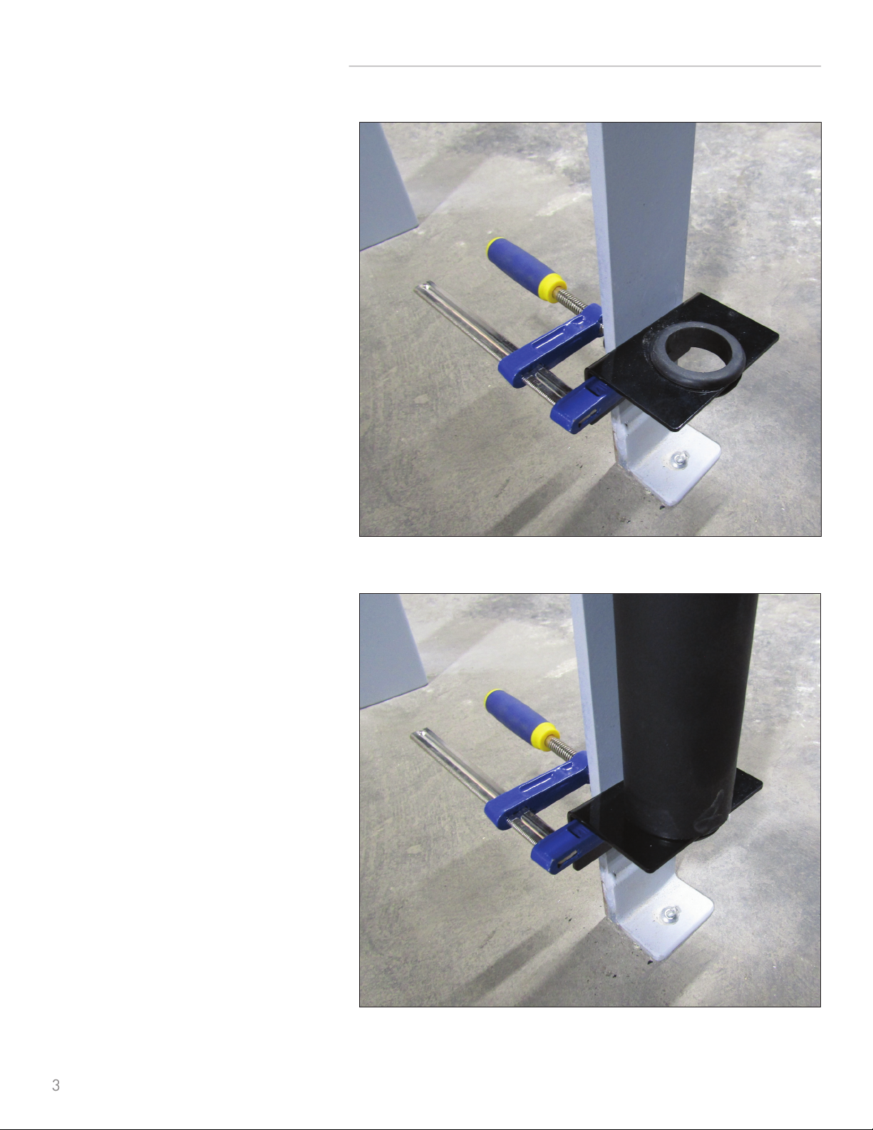
The ideal height for the winch handle that operates the
system is about 42” above the floor. This means that, on a
standard ladder, the winch portion of the Drive Unit should
be placed between the third and fourth ladder rungs. For a
nonstandard ladder, the installer can adjust the Drive Unit
location to the optimum height by moving the unit up or down
as needed to have the top and bottom bracket locations clear
of rungs (the top and bottom brackets are 5’ apart, so if one
bracket is clear of interference by a rung, they both should be).
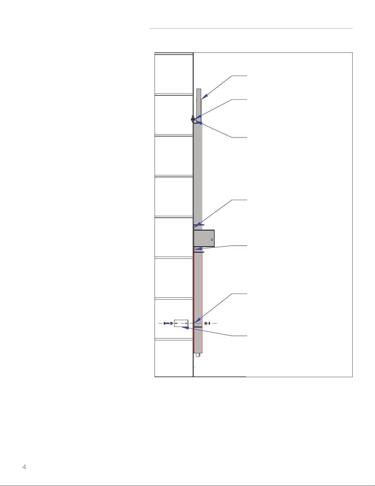
The winch housing, which is part of the Drive Unit, has two
available mounting positions, at least one of which should be
clear of a rung and which should be used to attach the unit to
the ladder. It is not necessary to use both of these winch
housing mounting points.
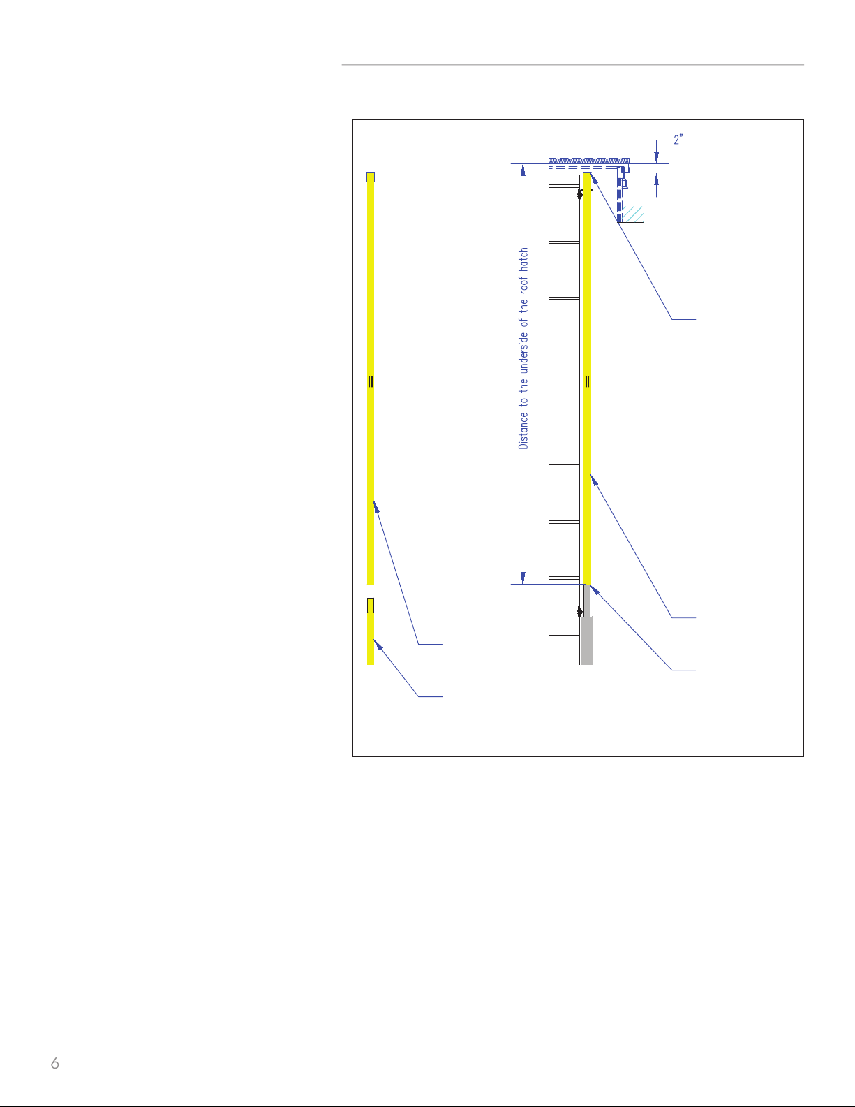
Each NextGen unit is manufactured using dimensions
provided by the buyer; therefore, the unit should fit with only
minor adjustments. The standard NextGen unit, which includes
the Drive Unit and the Lifting Tube, has a fully assembled height
of 13’-6” (162”). In the event that the hatch is more than 15’
from the floor, the necessary Lifting Tube Extension (or
Extensions) is included.
NextGen Lift & Lock Installation Manual 01.2021
1
TOOLS AND MATERIALS REQUIRED FOR INSTALLATION*
•Climbing helmet
•Climbing harness or fall protection harness
•Hard hat
•Two 6” or approximate clamps
•Two 7/16” box wrenches or sockets
•Drill with 1/8” bit
•3/4” wrench or adjustable wrench
•Two 9/16” box wrenches or sockets
•5/16” nut driver
•Blind rivet tool (optional)
•Tape measure
•Felt tip or other marker
•A-frame ladder (optional, if space allows and if
installer would prefer to work beside rather than on
the roof access ladder)
*Not included
2570 Blvd. of the Generals, Suite 200, Norristown, PA 19403 | [email protected] | 877.723.3766 | www.SafetyRailSource.com
NEXTGEN LIFT & LOCK ROOF ACCESS SAFETY SYSTEM PARTS
BSP ROOF ACCESS SAFETY SYSTEM PARTS
BSP Installatio Manual 01 .2021
8
7
1
11
16
12
15
13 14
45 6
32
9 10
Part 1 Drive Unit (1 included)
Part 2 Guide Bracket (2)
Part 3 Backing Plate (5)
Part 4 1/4" Bolt (10)
Part 5 1/4" Washer (20)
Part 6 1/4" Stop Nut (10)
Part 7 Lifting Tube (1)
Part 8 Optional Lifting Tube
Extension (1)
Part 9 1/8" Blind Rivet (8)
Part 10 Self-Tapping Screw (8)
Part 11 Hatch Opener Arm(1)
Part 12 Hatch Adaptor (1)
Part 13 7/16" Bolt (2)
Part 14 7/16" Stop Nut (2)
Part 15 Handle (1)
Part 16 Rubber Cap (1)
NO SCALE
2
Part 1 Drive Unit (1 included)
Part 2 Guide Bracket (2)
Part 3 Backing Plate (5)
Part 4 1/4" Bolt (10)
Part 5 1/4" Washer (20)
Part 6 1/4" Stop Nut (10)
Part 7 Lifting Tube (1)
Part 8 Optional Lifting Tube Extension (1)
Part 9 1/8" Blind Rivet (8)
Part 10 Self-Tapping Screw (8)
Part 11 Hatch Opener Arm (1)
Part 12 Hatch Adaptor (1)
Part 13 7/16" Bolt (2)
Part 14 7/16" Stop Nut (2)
Part 15 Handle (1)
Part 16 Rubber Cap (1)
2570 Blvd. of the Generals, Suite 200, Norristown, PA 19403 | [email protected] | 877.723.3766 | www.SafetyRailSource.com
NextGen Lift & Lock Installation Manual 01.2021
STEP 1
Determine at what height the Drive Unit (Part 1)
will be mounted (see Important Pre-Installation
Notes, Paragraph 6, for information on where
the Drive Unit should be positioned).
On the side of the ladder where the unit will
be mounted, clamp a Guide Bracket (Part
2) roughly 6” above the floor (see Illustration
1A). This Guide Bracket will help support the
Drive Unit while it is being installed; after the
Drive Unit is bolted on, the Guide Bracket will
be removed.
INSTALLATION INSTRUCTIONS
ILLUSTRATION 1A
ILLUSTRATION 1B
Position the Drive Unit on the Guide Bracket (see
Illustration 1B) so that the Drive Unit mounting
holes are against the ladder. Clamp the Drive
Unit to the side of the ladder.
3
2570 Blvd. of the Generals, Suite 200, Norristown, PA 19403 | [email protected] | 877.723.3766 | www.SafetyRailSource.com
NextGen Lift & Lock Installation Manual 01.2021
Mounting Holes - C
Mounting Holes - B
Backing plate with bolt,
washers and stop nut
Mounting Holes - A
Drive Tube
Mounting Holes - D
Backing plate with bolt,
washers and stop nut shown
as installed
ILLUSTRATION 1C
Bolt the Drive Unit to the side of the ladder
with a Backing Plate (Part 3) at the upper
and lower Drive Unit mounting holes (A and
D—see Illustration 1C), using ¼” Bolts (Part
4), ¼” Washers (Part 5), and ¼” Stop Nuts
(Part 6). Use only the top and bottom Drive Unit
mounting holes (A and D), not mounting holes
B and C. Tighten bolts only until the Drive Unit
stays in place; do not over-tighten bolts at this
step.
Remove the Guide Bracket and the clamp that
temporarily held the Drive Unit in place.
INSTALLATION INSTRUCTIONS
4
2570 Blvd. of the Generals, Suite 200, Norristown, PA 19403 | [email protected] | 877.723.3766 | www.SafetyRailSource.com
NextGen Lift & Lock Installation Manual 01.2021
Ladder side
Backing Plate
Guide
Bracket
ILLUSTRATION 2
INSTALLATION INSTRUCTIONS
STEP 2
Attach a Guide Bracket to the top of the ladder
on the side where the Drive Unit is mounted,
using one Backing Plate, two ¼” Bolts, four ¼”
Washers, and two ¼” Stop Nuts (see Illustration
2). This Guide Bracket should be as close to the
top of the ladder as possible, but no closer than
4” below the underside of the closed hatch.
5
2570 Blvd. of the Generals, Suite 200, Norristown, PA 19403 | [email protected] | 877.723.3766 | www.SafetyRailSource.com
NextGen Lift & Lock Installation Manual 01.2021
STEP 3
Ensure that the roof hatch is closed.
Measure from the shoulder of the Drive Tube
(located at the top of the Drive Unit—see
Illustration 3) to the underside of the roof hatch.
Identify the Lifting Tube (Part 7).
If this installation requires an Optional Lifting
Tube Extension (Part 8), insert the Extension
into the bottom of the Lifting Tube. (Note: If an
Extension is required based on the dimensions
provided by the buyer, that Extension will be
included in the shipment; no Extensions are
included if not needed.) Align the pre-drilled
holes in the Lifting Tube and the Extension.
Connect the two with 1/8” Blind Rivets (Part
9) or Self-Tapping Screws (Part 10).
Measure the length of the Lifting Tube (or, if an
Extension has been inserted, measure the entire
length of the Lifting Tube and the Extension).
The Lifting Tube assembly should be 2” shorter
than the distance from the shoulder of the Drive
Tube to the underside of the roof hatch (see
Illustration 3).
If necessary, adjust the mounting location of the
Drive Unit—moving it up or down—to ensure
that the Lifting Tube assembly is 2” shorter than
the distance from the shoulder of the Drive Tube
to the underside of the roof hatch.
INSTALLATION INSTRUCTIONS
Lifting Tube
top position
Lifting Tube
(Part 7)
Drive Tube
Shoulder
Lifting Tube
(Part 7)
Optional Lifting Tube
Extension (Part 8)
ILLUSTRATION 3
6
2570 Blvd. of the Generals, Suite 200, Norristown, PA 19403 | [email protected] | 877.723.3766 | www.SafetyRailSource.com
NextGen Lift & Lock Installation Manual 01.2021
STEP 4
With the roof hatch open, insert the top of the Lifting Tube into the top Guide Bracket from below and slide it up until the bottom
of the tube can be seated on the Drive Tube. The flanges on the Lifting Tube should be perpendicular to the ladder rungs (see
Illustration 4).
INSTALLATION INSTRUCTIONS
Ladder side
Ladder rung
Lifting Tube
Lifting Tube
Flanges
ILLUSTRATION 4
7
2570 Blvd. of the Generals, Suite 200, Norristown, PA 19403 | [email protected] | 877.723.3766 | www.SafetyRailSource.com
NextGen Lift & Lock Installation Manual 01.2021
STEP 5
At the beginning of Step 5, the Drive Unit should be bolted to the ladder, and the Lifting Tube should be seated on the Drive Tube
at the top of the Drive Unit.
Attach the Hatch Opener Arm (Part 11) to the Hatch Adaptor (Part 12), using a 7/16” Bolt (Part 13) and 7/16” Stop Nut
(Part 14) (see Illustrations 5A and 5B).
Attach the Hatch Opener Arm to the Lifting Tube, using a 7/16” Bolt and a 7/16” Stop Nut (see Illustrations 5C and 5D).
INSTALLATION INSTRUCTIONS
ILLUSTRATION 5B
ILLUSTRATION 5DILLUSTRATION 5C
ILLUSTRATION 5A
8
2570 Blvd. of the Generals, Suite 200, Norristown, PA 19403 | [email protected] | 877.723.3766 | www.SafetyRailSource.com
NextGen Lift & Lock Installation Manual 01.2021
STEP 6
STEP 7
Attach the Handle (Part 15) to the Drive Unit
(see Illustration 6).
Close the roof hatch. Manually raise the Hatch
Opener Arm until the flat side of the Hatch
Adaptor is in full contact with the underside
of the roof hatch. If this is possible, proceed to
Step 8. If there is a small gap between the flat
side of the Hatch Adaptor and the underside
of the roof hatch, use the Drive Unit Handle
to raise the Lifting Tube until the flat side of the
Hatch Adaptor is fully against the underside of
the roof hatch (see Illustration 7).
INSTALLATION INSTRUCTIONS
ILLUSTRATION 6
ILLUSTRATION 7
9
Hatch
Lifter
Lifting
Tube
Rubber Cap
Hatch
Adaptor
2570 Blvd. of the Generals, Suite 200, Norristown, PA 19403 | [email protected] | 877.723.3766 | www.SafetyRailSource.com
NextGen Lift & Lock Installation Manual 01.2021