Safetytest 1ST User manual

SAFETYTEST 1ST User Manual
SAFETY
TEST
SAFETYTEST GmbH June 15
th
2015 Page 1 of 22
SAFETYTEST 1ST User Manual
Figure 1

SAFETYTEST 1ST User Manual
SAFETY
TEST
SAFETYTEST GmbH June 15
th
2015 Page 2 of 22
Texts, drawings and technical information were prepared with great care. However, errors
may still be present. The author and the manufacturer assume no direct or indirect liability for
any incorrect or incomplete descriptions or any damages that may occur.
The user manual should be read carefully and completely before using the tester.
Warning markings in the manual and on the clamp are meant to warn of risks or dangers.
Warning markings in the manual on the tester and on the accessories have to be adhered to
and describe the following:
General warning, warning of a danger!
See user manual!
Warning of hazardous electrical voltage!
Warning when exchanging fuses!
Warning of the risk of fire, e. g. when using improper fuses!

SAFETYTEST 1ST User Manual
SAFETY
TEST
SAFETYTEST GmbH June 15
th
2015 Page 3 of 22
Table of Contents
1
General Safety and Warning Notes.......................................................................5
2
Application.............................................................................................................6
3
Scope of Delivery and Accessories......................................................................6
3.1
Scope of Delivery (Standard):.....................................................................................6
3.2
Accessories (optional):................................................................................................6
3.3
Software (Optional):....................................................................................................6
4
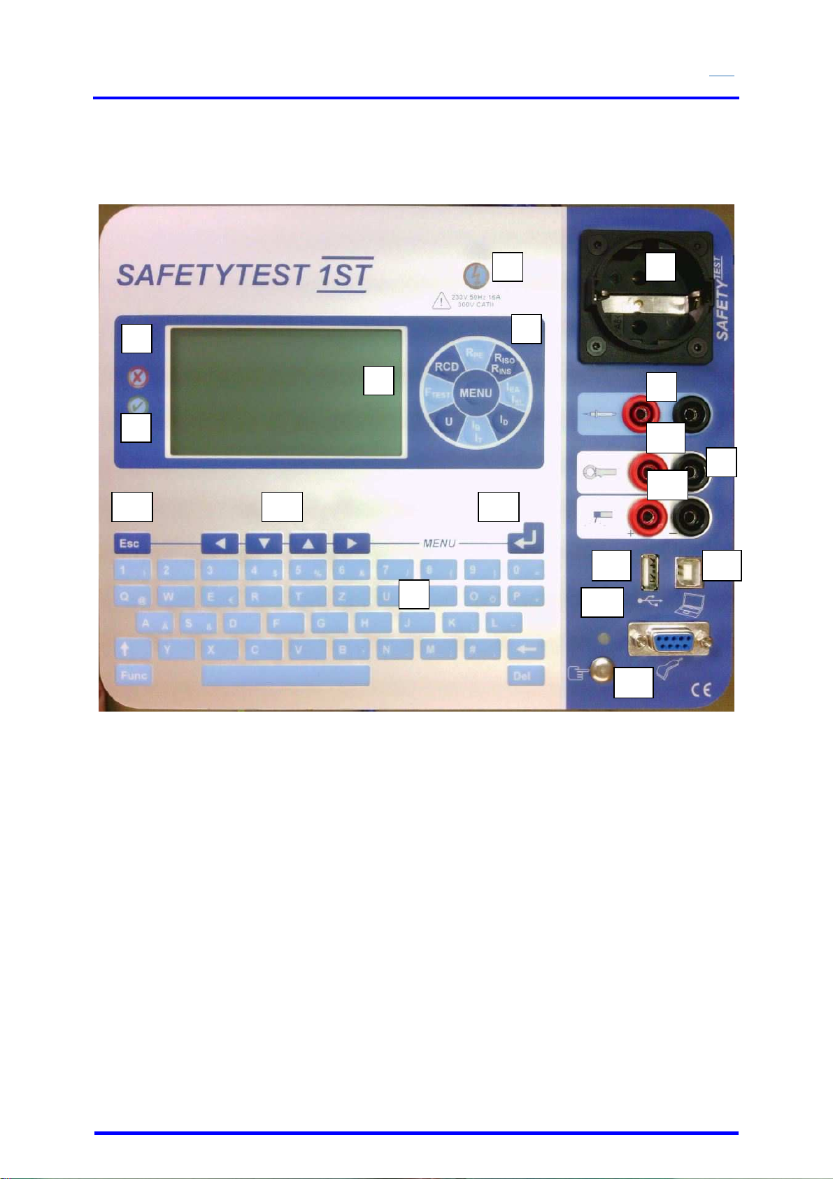
Connections, Display and Keyboard....................................................................7
4.1
Connections (Figure 2) ..............................................................................................8
4.2
Mains connection „Input“, Type Schuko......................................................................8
4.3
Measuring socket “GND“(Figure 2/9)..........................................................................8
4.4
Measuring sockets “Probe“(Figure 2/8).......................................................................8
4.5
Schnittstelle PC-COM (Figure 2/11)............................................................................8
4.6
Interface USB (Figure 2/12)........................................................................................8
4.7
Test sockets (Figure 2/4)............................................................................................8
4.8
Keyboard and Display.................................................................................................8
4.9
Display (Figure 2/5) ....................................................................................................9
5
Functional Description..........................................................................................9
5.1
Power Supply .............................................................................................................9
5.2
Internal memory..........................................................................................................9
5.3
Interface RS232/USB..................................................................................................9
5.4
Display and Keyboard.................................................................................................9
6
Testing the Mains Connection..............................................................................9
7
Connection Test...................................................................................................10
7.1
AC Connection..........................................................................................................11
8
Display and Menu Structure................................................................................11
9
Taking the Tester into Operation........................................................................11
9.1
Visual check .............................................................................................................11
9.2
Connecting the tester to the mains system ...............................................................11
9.3
Starting the test.........................................................................................................11
10
Testing Electrical Appliances .............................................................................11
10.1
Qualification..............................................................................................................12
10.2
Mains connection......................................................................................................12
10.3
Visual inspection.......................................................................................................12
10.4
Measurements..........................................................................................................13
10.5
Functional Test.........................................................................................................13
10.6
Checking the Markings .............................................................................................13
10.7
Documentation of the test.........................................................................................13
11
Connections, Pictures, Examples.......................................................................14
11.1
Earth bond test of AC appliances..............................................................................14
11.2
Earth bond test of three phase equipment using a test lead......................................14
11.3
Earth bond test of three phase equipment using the extension lead adapter ............15
11.4
Accessible conductive parts not connected to PE.....................................................15
11.5
Insulation resistance test LN-PE...........................Fehler! Textmarke nicht definiert.
11.6
Insulation resistance test LN-PE of three phase equipment using the extension lead
adapter.............................................................................................................................16
11.7
Earth leakage test of AC appliances with plug..........................................................16
11.8
Earth leakage test on three phase equipment using the three phase adapter...........16
11.9
Extension lead test ...................................................................................................17
11.10
Extension cable testing...........................................................................................17
11.11
Testing Welding appliances ....................................................................................19

SAFETYTEST 1ST User Manual
SAFETY
TEST
SAFETYTEST GmbH June 15
th
2015 Page 4 of 22
12
Updating the Firmware........................................................................................20
13
Error messages, Removing Faults .....................................................................21
13.1
The display remains dark..........................................................................................21
13.2
Touch current display is 0,000 mA...........................................................................21
13.3
Contact current measurement larger than 0,5 mA.....................................................21
13.4
Leakage current measurement shows “F“ as a result................................................21
14
Spare Parts...........................................................................................................21
15
Technical Data .....................................................................................................21
16
Disposal................................................................................................................22
17
Guarantee.............................................................................................................22

SAFETYTEST 1ST User Manual
SAFETY
TEST
SAFETYTEST GmbH June 15
th
2015 Page 5 of 22
1 General Safety and Warning Notes
The tester “Safetytest 1ST” was built and complies with the following safety standards.
DIN EN 61010-1 (VDE 0411 part 1),
SAFETY REQUIREMENTS FOR ELECTRICAL EQUIPMENT FOR
MEASUREMENT, CONTROL, AND LABORATORY USE
DIN VDE 0404 parts 1 and 2,
“Geräte zum Prüfen, Messen oder Überwachen von Schutzmaßnahmen“
Immunity according to DIN EN 61326,
“Elektrische Betriebsmittel für Leittechnik und Laboreinsatz - EMV-Anforderungen“
In order to warrant the safe application of the tester the following warnings have to be
adhered to:
All tests may only be carried out by a skilled electrician or under
the supervision of a skilled electrician. The qualified person must
be trained for the specific task.
The tester subject only to its intended use. The warning markings
on the tester, the connecting cables and accessories have to be
observed.
The tester may be used only on 230V AC main systems which are
protected with max 16A circuit breakers or fuses.
Measurements may not be performed on unfused circuits.
Repairs and alterations to the tester may be carried out only by the
manufacturer or by a service organization qualified by the
manufacturer. Repairs on the supply leads or adapter cables may
be carried out only by skilled electricians.
Only original spare parts supplied by the manufacturer may be
used.
Fuses may be replaced only by the original fuses of the
manufacturer.
If a safe application is not possible, e. g. due to:
-
Visual defects,
-
Improper storage,
-
Improper transport,
-
Failure of a phase control lamp,
-
Failure of measurement functions,
the tester must be decommissioned! Repair may be done only by
the manufacturer or a service organization authorised by the
manufacturer.

SAFETYTEST 1ST User Manual
SAFETY
TEST
SAFETYTEST GmbH June 15
th
2015 Page 6 of 22
Earth bond tests and touch current tests in power systems are
only allowed in specific cases and when regarding the appropriate
safety precautions.
Note that large voltages may appear on appliances during tests,
e. g. by charged capacitors.
Only connect the appliance that is being tested to the power
socket once the power system is safe!
NOTE! When connecting the appliance to mains, hazardous
voltages may occur on a defective appliance or on conductive
parts which are not connected to PE.
2 Application
The tester “SAFETYTEST 1ST” is used for testing the electrical safety of appliances.
3 Scope of Delivery and Accessories
3.1 Scope of Delivery (Standard):
•1 probe lead for R
PE
+ I
B
(2 m) (Art.-Nr.: 0003330)
•1 user manual (English) on CD incl. . (Art.-Nr.: 0019800)
•1 protocol software SAFETYDOC DEMO
•1 power cord 1,8 m (Art.-Nr.: 0004520)
•1 connector cable 1ST (Art.-Nr.: 0009420)
3.2 Accessories (optional):
Accessories Material Number
SAFETYTEST DI40 Differential current clamp/current clamp 6733040
Safety Clamp 4 mm black 0001002
Brush probe 4 mm black for effective protective conductor measurements 0001001
Test lead with test probe 4 mm yellow 6462210
Kelvin probe 2 x 4 mm socket 5 m 0002840
Mete rotary power 16A 0037510
Mete rotary power 32A 0037520
Barcode scanner 0001190
Barcode printer 0002620
Transponder reader 0001008
Carrying case for accessories 6124910
3.3 Software (Optional):
Remote control and database software safety-remote Nr. 0001004
Protocol- and table software Nr. 0001005

SAFETYTEST 1ST User Manual
SAFETY
TEST
SAFETYTEST GmbH June 15
th
2015 Page 7 of 22
4 Connections, Display and Keyboard
Figure 2
1. OK LED indicates a PASSED test result
2. FULT LED
3. Panel for individual measurements
4. Glow lamp indicating that mains is connected to the test socket
5. Test socket
6. LCD – display
7. Alphanumeric keypad
8. Connection sockets for the test probe (red + black)
9. Clamp connection and GND connection for voltage measurement over the probe
connected to PE potential when mains is switched to the test socket
10. Clamp connection for the differential current clamp/ line current clamp
11. Welders electrode terminal
12. RS232 interface over an extension cable from the PC for connection of the barcode
scanner, transponder scanner and serial line printer.
13. USB PC connection
14. Interface for Memory Stick
15. Finger contact
16. “Enter – key” to input and confirm the Menu
17. Navigation keypad to move the cursor
18. “ESC – key” to cancel measurements or to toggle into the previous Menu.
1
2
4 5
6
7
8
9
10
11
12
13
3
14
15
18 17 16

SAFETYTEST 1ST User Manual
SAFETY
TEST
SAFETYTEST GmbH June 15
th
2015 Page 8 of 22
4.1 Connections (Figure 2)
Before connecting the tester to the mains, the appropriate warnings in chapter 1 have
to be observed, as well as the warnings for connecting the leads and accessories
attached. It is safe to use the instrument for its intended use only. The testing of the
rotective conductor potential takes place through using the fingercontact after the
tester is connected.
4.2 Mains connection “Input“, Type Schuko
The tester may be connected only to a power system of 230 V AC 40 – 60 Hz,
protected by a circuit breaker of max 16 A.
4.3 Measuring socket “GND“ (Figure 2/9)
Connection for the negative pole for temperature and voltage measurements and the
current clamp.
4.4 Measuring sockets “Probe“ (Figure 2/8)
Connection for the probe for earth bond and touch current measurements. Check the
polarity when connecting the key probe!
4.5 Schnittstelle PC-COM (Figure 2/11)
Connection for a 9 pin D-sub connector for the serial interface
RS 232 (19200, N, 8, 1) for:
Transferring data to and from the PC (alternative to using USB)
Firmware updates (limits, test sequences, measuring functions, languages,…) (alternative to
using USB)
Barcode scanner
Transponder scanner
Printer - a separate power supply is needed.
Note: The interface may be connected to a USB port by using an optional USB-RS232
converter.
4.6 Interface USB (Figure 2/12)
Connection to a USB connector to communicate with the PC via a virtual Com
interface. The driver of FTDI has to be installed and is available on the CD which
comes with the tester. This took place during the installation of the software.
4.7 Test sockets (Figure 2/4)
Connection for a USB plug to connect a USB memory stick, a HID barcode, a
transponder reader or a keyboard.
NOTE!!!
When connecting a faulty appliance to the test socket a hazardous voltage may
occur when mains is applied on accessible conductive parts not connected to the
protective earth and on the housing if the protective earth is out of order.
4.8 Keyboard and Display
The keyboard allows an easy way to perform all tests and the display shows all
results.

SAFETYTEST 1ST User Manual
SAFETY
TEST
SAFETYTEST GmbH June 15
th
2015 Page 9 of 22
4.9 Display (Figure 2/5)
The display has a resolution of 320x240 pixels and is backlit. The menus, help texts,
measurement functions, limits, measured values and quantities are displayed as text
messages. Several languages are possible.
5 Functional Description
5.1 Power Supply
The device is powered with mains (230V ±10%). The electronic measurements are supplied
by an internal fuse.
5.2 Internal memory
The measurements are performed according to a menu and the results stored in the internal
memory of the tester.
The inventory data and the measured values can be transferred to the PC. Inventory data
and the test profile may also be transferred from the PC to the tester.
5.3 Interface RS232/USB
The Barcodescanner can be connected using the RS232 interface.
NOTE!!!
All contacts of the extension lead must be connected 1:1.
USB: The tester is connected to the PC via a standard USB type B interface cable. The FTDI
is installed with the PC software.
The baud rate to the PC is 19200 baud.
The interface is galvanically isolated.
The firmware of the “SAFETYTEST 1ST” may be updated easily via the USB/COM interface.
An update allows you to get the latest testing sequences and change the display language,
The optional barcode scanner or the transponder scanner used for scanning ID numbers from
the UUTs may be connected to the RS232 interface. Both are pre configured to 19200 baud.
5.4 Display and Keyboard
The display and keyboard are supplied by their own circuitry.
6 Testing the Mains Connection
The person responsible for the electrical installation is responsible for the safety of the power
system to which the tester is connected.
The test of the installation is not part of the appliance test. However, it is important to know
before testing if the electrical installation is safe.
The tester does not perform a complete test as required by DIN VDE 0100.
Nevertheless a few important measurements are made giving an indication of the mains
connection, as for example:
•Testing of the protective earth potential using the fingercontact
•Mains PE against N voltage < 30V.
•Check if the N conductor is open circuit (the display does not light up).
•Display of the orange phase check glow lamp if mains is on (yellow light)
•Voltage measurement phase against N (range 1 to 260V AC)

SAFETYTEST 1ST User Manual
SAFETY
TEST
SAFETYTEST GmbH June 15
th
2015 Page 10 of 22
Note:
•Through touching the the fingercontact, it is possible to deteremine whether
the protective conductor is connected. This is not the case, if after touching
the fingercontact the red LED lights up.
•If the mains connection is faulty a message “PE>30V!!“ is displayed on the
display. Further, the tester makes a loud beep sound. Further tests may only
be performed after the power system has been repaired.
•If N/PE are exchanged the RCD of the installation switches off
•If no display appears PE may be hazardous live. Test this using the
fingercontact. Disconnect tester from the mains and check on another mains
socket. If the tester now works, get a specialist to check the faulty mains
socket.
•Around an IT-network, the protective conductor is not on PE potential. If
“PE>30V” appears. If the tester is connected through an isolation
transformer, the PE is missing. “PE>30V” appears.
7 Connection Test

SAFETYTEST 1ST User Manual
SAFETY
TEST
SAFETYTEST GmbH June 15
th
2015 Page 11 of 22
In the first Menu “Connection”, the available mains voltage and the N and PE conductor
terminal are displayed.
7.1 AC Connection
NOTE!!!
•If the voltage L1 < 207 V or L1 > 253 V no proper measurements can be
made.
If the message “PE>30” appears it is most probable that the PE conductor is not connected to
the mains power socket. It may also happen that the PE conductor is connected but that it is
hazardous live (test using the fingercontact)! For checking the PE conductor refer to the
chapter “Mains Connection” above.
8 Display and Menu Structure
The display allows a comfortable menu based testing sequence, shows all measuring
functions, limits and values. The menu structure is documented in a separate document
“SAFETYTEST 1ST-Menu Structure”. It is kept up to date together with the software.
9 Taking the Tester into Operation
9.1 Visual check
•Observe the safety precautions of chapter 1.
•Check the mains connection, tester and accessories
•Observe all warning markings on the tester mains cord and accessories!
9.2 Connecting the tester to the mains system
•The tester is supplied from the mains input.
9.3 Starting the test
Follow the menu of the tester.
10 Testing Electrical Appliances
The tests required by the standards have been realised by the internal testing sequences.
Before starting a test the appliance has to be classified in the profile menu.
After repair, modification and after repetitive testing electrical appliances have to provide a
degree of safety to the user which is comparable of that of brand new appliances. Whether
the safety is given can be tested according to the applicable standard. The following tests are
to be performed in the given order. Each test step must have been passed before proceeding
to the following step:
•Visual inspection
•Earth bond test
•For class I appliances test of the insulation resistance and or the earth leakage
current or the substitute leakage current.
•For class II equipment as well as for accessible conductive parts not connected to PE
of class I equipment, the insulation resistance and the touch current or the substitute
leakage current.
•Functional Test
Notes:
Before performing a leakage test on class I appliances the earth bond test has to be passed.

SAFETYTEST 1ST User Manual
SAFETY
TEST
SAFETYTEST GmbH June 15
th
2015 Page 12 of 22
Before performing a leakage current test on class II or III (except for IT appliances) an
insulation resistance test of 500 V DC has to be passed. Accessible connections and
generated SELV voltages have to be checked according to the SELV specifications.
10.1 Qualification
High requirements are set to the qualification of the skilled electrician. All tests have to be
performed by a skilled electrician or under his supervision. The skilled electrician must follow
the rules and standards required for his work. Also it is not allowed to omit any steps which
would ensure a correct and safe use of the appliance. The liability of the skilled person
responsible for testing is especially important if no complete test is possible (e. g. due to
permanently installed equipment). If a complete test is impossible the responsible electrician
assumes the liability and has to document this on the test report.
10.2 Mains connection
According to law the person responsible for the installation of the power system is
responsible for the mains connection, not the manufacturer of the equipment to be
connected.
The required tests on permanently installed equipment are often not possible due to technical
reasons or due to the local conditions. If the equipment is not accessible the mains
connections (L1, L2, L3, N and PE) have to be disconnected from mains. Therefore the
connection should be refitted to a plug and socket connection according to IEC 60309-1 or a
coupling should be inserted according to IEC 60309-1. The installation costs can be
amortized du to a faster safety test.
NOTE!!!
Electrical appliances with a nominal current above 16A must be connected to all pole circuit
breakers according to IEC 60947. These should be mounted at a height of approx 1,7 m.
Plugs and sockets of equipment rated above 16A may not be connected or disconnected
under load. Always open the circuit breaker first.
Equipment rated below 16A does not require a separate circuit breaker.
10.3 Visual inspection
The appliances are checked for externally visible damages, and, if possible, the suitability of
the surrounding for their use e. g.:
-
Damages to the housing
-
Suitable place of installation
-
Damages to the power cord
-
Deficiencies on the strain relief
-
Indications of overload or improper use
-
Inappropriate alterations
-
Missing protective covers
-
Dirt and corrosion affecting safety
-
Presence of required ventilators
-
Open air vents
-
Tightness
-
Legibility of markings
Note:
Visible damages which might impel the mechanical or electrical safe use or which might lead
to fire must be repaired immediately.

SAFETYTEST 1ST User Manual
SAFETY
TEST
SAFETYTEST GmbH June 15
th
2015 Page 13 of 22
10.4 Measurements
See menu system
10.5 Functional Test
After performing the electrical test a functional test is required. A short test may be sufficient.
10.6 Checking the Markings
The presence of safety required markings must be checked and if necessary renewed or
completed.
10.7 Documentation of the test
The passed test has to be documented. If an appliance is unsafe, this must be marked clearly
on the appliance and the responsible body to be notified in writing. The measurement values
and alterations performed are to be documented. The appliance should be marked by a
sticker that for example states the following: “Tested according to VDE 0701-0702 and DGUV
Standards 3” .

SAFETYTEST 1ST User Manual
SAFETY
TEST
SAFETYTEST GmbH June 15
th
2015 Page 14 of 22
11 Connections, Pictures, Examples
11.1 Earth bond test of AC appliances
Protective conductor: Use the protective conductor probe to scan the housing parts and
move the connection cord.
11.2 Earth bond test of three phase equipment using a test lead
Earth bond test: Use the probe to test all conductive parts connected to PE. Move the power
cord.
Permanently connected equipment: Use the profile “Fixed equipment”. Connect the tester to
mains. Probe all conductive parts connected to PE. The earth bonding is tested via the PE
connection of the tester, the installation and the connection of the unit under test. Therefore
the limit value is higher than the normal limit value.

SAFETYTEST 1ST User Manual
SAFETY
TEST
SAFETYTEST GmbH June 15
th
2015 Page 15 of 22
11.3 Earth bond test of three phase equipment using the extension lead adapter
Testing sequence: „Cl with Clamp“. Connect the test lead to the yellow connection on the
tester and the large earth pin on the CEE connector. Probe all earthed parts of the appliance
under test.
11.4 Accessible conductive parts not connected to PE
Testing sequence: „Cl with Clamp“. Connect the extension lead adapter to the tester and plug
the appliance into the CEE socket. Probe all earthed parts of the appliance under test.
11.5 Exposed insulated conductive parts
Testing conductive parts not connected to PE: Use the probe to test these parts. If there
are rotating or moving parts test these in motion. The best way is to use the optional brass
brush probe. Use protective glasses.

SAFETYTEST 1ST User Manual
SAFETY
TEST
SAFETYTEST GmbH June 15
th
2015 Page 16 of 22
Insulation resistance test LN-PE, Substitute leakage test: Connect appliance to test
socket. Switch on the appliance. The test is done without applying mains.
11.6 Insulation resistance test LN-PE of three phase equipment using the
extension lead adapter
11.7 Earth leakage test of AC appliances with plug
Testing sequence: „Cl with Ins test“. Connect the extension lead adapter to the tester and
plug the appliance into the CEE socket. Turn on the appliance under test.
11.8 Earth leakage test on three phase equipment using the three phase adapter
Earth leakage test, functional test: Connect the appliance to the test socket. The appliance
is tested with mains applied to it.

SAFETYTEST 1ST User Manual
SAFETY
TEST
SAFETYTEST GmbH June 15
th
2015 Page 17 of 22
11.9 Extension lead test
Connect the adapter to a CEE socket of the installation. Connect the appliance to the socket
of the adapter. Use the current clamp to encompass L1, L2, L3 and N without PE Connect the
current clamp to the tester.
Measurement in menu “Cl I with Clamp” or “Fixed Connection”
11.10 Extension cable testing
As an option several extension lead sets are available for
single and three phase equipment. Three phase adapters:
Connect the AC plug into the tester. Connect the extension lead between the adapters.
Connect the probe to the banana socket of the extension lead adapter plug. Start the
extension lead test. The following tests are performed:
-
earth bond continuity of the extension lead
-
insulation between L1, L2, L3, N and earth
-
continuity and phase rotation of the extension lead.

SAFETYTEST 1ST User Manual
SAFETY
TEST
SAFETYTEST GmbH June 15
th
2015 Page 18 of 22
During the PRCD-S test, the Schuko plug is inserted into the test socket of the tester. The
other side of the extension cord is inserted into the panel plug on the right-hand side of the
tester or an adapter as shown in the figure above. Start extension lead test. Choose PRCD-S
and adjust tripping current before starting.

SAFETYTEST 1ST User Manual
SAFETY
TEST
SAFETYTEST GmbH June 15
th
2015 Page 19 of 22
11.11 Testing Welding appliances
During the testing of welding equipment, both electrodes, as shown in the figure, are attached
to the tester. The power cord of the welding quipment is attached to the power socket of the
tester. Select “VDE 0544-4” in the menu, set it to the open-circuit voltage and start the test.
Follow the testing procedures.

SAFETYTEST 1ST User Manual
SAFETY
TEST
SAFETYTEST GmbH June 15
th
2015 Page 20 of 22
12 Updating the Firmware
Connect the tester to the USB interface of the PC.
Start the PC program Bootloader.
Select the COM port in the menu
Select the menu „Open Hex File“
Disconnect the power plug from the tester.
Select the “Connect” button. The green “Progress” bar will slowly be filled.
Connect the tester to the power. The green “Progress” bar will be filled.
Select the “Program” button.
After completing the programming of the tester, disconnect it from the power and reconnect it
again.
Table of contents
Other Safetytest Test Equipment manuals