9
Copyright Safewaze 2022
LIFELINE
S. Stoplink Brake V2 (019-8044): TheStoplink Brake is
an in-line energy absorber. The Stoplink brake includes
a built-in tension indicator, which displays whether or
not the Mobile SafeLink system has been properly
tensioned.
T. Cable (FS-EX2500-GA): The cable in the Mobile
SafeLink Horizontal Lifeline System is 5/16 in (7.94 mm)
7 x 19 galvanized aircraft cable. A minimum of two (2)
cable fist-grips are used to secure the ends of the cable.
U. Snap hooks and Carabiners (FS1015): used with
the Mobile SafeLink Horizontal Lifeline System, marked
with the ANSI Z359.12-2009 standard, are self-locking
with a minimal tensile breaking strength of 5,000 lbs
(2267.96 kg) and a 3,600-lb (1632.93 kg) gate rating.
Snap hooks and carabiners marked to the ANSI
Z359.12-1999 standard incorporate self-locking snap
hooks and carabiners with minimal tensile breaking
strength of 5,000 lbs (2267.96 kg), and minimum gate
rating of 220 lbs (99.79 kg) and a minimum side-load
gate rating of 350 lbs (158.76 kg).
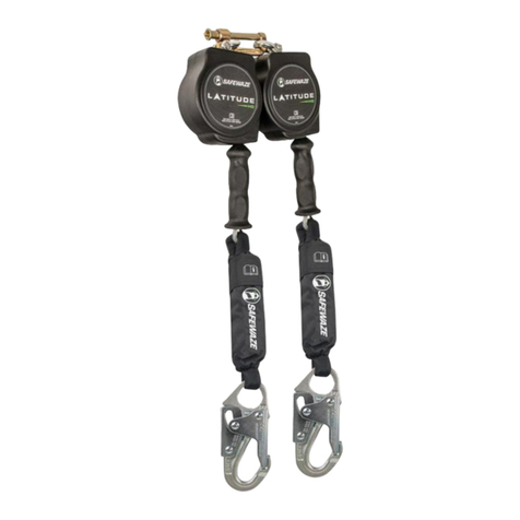
V. Retractable (SRL): The SafeLink System is
compatible with any Class A or Class B Self Retracting
Lifeline. This also includes competitor models.
INSTALLATION—ANCHORAGE CONNECTORS 9
DO NOT USE A PVC SLEEVE THAT
DOES NOT MEET ALL OF THESE
REQUIREMENTS.
Installation of PVC Sleeve for
Aluminum Post
Cut PVC sleeves to 12 in (304.8 mm),
and cast sleeves into freshly poured
concrete of 2,000 PSI (13.8 MPa) or
greater. Use duct tape to seal the ends
of the PVC sleeve, preventing fresh
concrete from filling the sleeve. The PVC
sleeve must not be cast into concrete
within 3-1/2 in (88.9 mm) of any concrete
edge. When stirrups exist in the column
within 2-1/2 in (63.5 mm) of the top
surface, the minimum column size must
be no less than 12 in (304.8 mm) in either
direction. When no stirrups exist, the
minimum column size must be no less
than 17 in (431.8 mm).
PVC sleeve should be plumb and must
be cast to a minimum depth of 11 in
(279.4 mm). Ensure the PVC sleeves do
not float upwards in the concrete before it
sets. To help keep sleeves from floating,
punch a small air hole through the duct
tape on the bottom of the sleeve, and use
a vertical 2x4 in the sleeve, nailed to the
top of the form. This method will also help
ensure the sleeve stays plumb.
A sleeve should normally be placed at
the center of the column section. This will
minimize the tendency to split the column.
When sleeves are placed at the center
of the column section, and when column
ties exist in the concrete within 2-1/2 in
(63.5 mm) of the top surface (thereby
crossing the potential fracture surface),
the minimum column size permitted is 12
in (304.8 mm) measured perpendicular
to the direction of the span of the lifeline
system. When there are no such ties, the
minimum column dimension measured
perpendicular to the span of the lifeline
system is 17 in (431.8 mm). Sleeves
should never be placed closer than 3-1/2
in (88.9 mm) to any edge of the column
cross-section.
When possible, request that a column tie
be located approximately 2 in (50.88 mm)
below the top surface of the column pour
(Only one tie shown in Fig.1 for clarity).
The aluminum post is
7 ft-6 in (2.29 m) long.
With a 12 in (304.8 mm)
embedded sleeve to
support the post, the
height of the horizontal
lifeline is approximately
6 ft-6 in (1.98 m) above
the poured height of
the column. At this
height, the average
employee should pass
easily under the cable
and conveniently reach it to attach a
self-retracting device.
It is easier and safer to assemble as
much of the SafeLink System as possible
before raising the assembly to the elevat-
ed location. Generally, the horizontal life-
line can be attached to the posts before
inserting the posts into the column tops.
Final tension of the horizontal lifeline,
however, must always be completed with
the posts set into the sleeves.
Reinforced Cross-Arm Strap
To secure the Cross-Arm Strap, wrap the
strap around the concrete column at a
height of at least 6 ft-6 in (1.98 m) above
the walking / working surface using a
choker hitch. This is done by passing one
end of the strap through the other end
and cinching. Attach the Stoplink Brake
by use of a carabiner. Secure the other
end of the lifeline to column by tensioning
the line as required.
10,000 lb (4535.92 kg) Removable
Concrete Anchor
The Removable Concrete Anchor is a
reusable concrete anchor designed to be
used with horizontal lifelines. This device
is made for use with concrete columns
or walls with a compressive strength of
3,000 PSI (20.7 MPa). The 10,000-lb
(4535.92 kg) rating is in any direction up
to 90º when placed in concrete. Install the
anchor in accordance with user instruc-
tions. Attach Stoplink Brake by use of
carabiner to Concrete Anchor eyelet.
RebarLink
The RebarLink Bracket is to be installed
6-1/2 ft (1.98 m) above the working
surface. With the eye-bolt facing outward,
*Only one tie
shown for clarity
Sleeve no closer than
3-1/2 in (88.9 mm)
to any side of the column
17 in (431.8 mm) minimum
with tie > 2-1/2 in (63.5
mm) below top of concrete
12 in (304.8 mm) minimum
with tie < 2-1/2 in (63.5 mm)
below top of concrete
Depth of
column tie
Fig. 1
place the bracket face
perpendicular to the front of the
rebar, centered on the cage. Slide
the supplied cinching rebar bolts
through both plates and tighten
together with supplied wing nuts
so that the Rebar Link is tightened
onto the rebar cage (See Fig. 2).
NOTE: When using the RebarLink,
Aluminum Posts are not used.
FormLink
The FormLink Bracket must be
attached to the base of a rebar
cage. Receiver sleeve must face
the direction of tension in the
system. To attach the FormLink
Bracket to the base of the rebar
cage, place the front and back
bracket at the top of the concrete
base. Slide the threaded bars
through the holes on the front
bracket into the slots of the back
bracket. The front and back panels
of the FormLink Bracket must
capture a minimum of six (6) #7 or
larger rebar, two (2) with the front
panel and two (2) with the back
panel, with the threaded bars.
Hand-tighten all four (4) wing nuts,
then add an additional 1/2 in (12.7
mm) turn to secure.
Rebar Link Typical
Installation
Fig. 1
Fig. 2
