Sagem My X-5 Guide

SITE TECHNICAL DOCUMENTATION
GSM 900/1800 - myX-3 & myX-5
Doc. No. : SCT U38 SSC DTS 009
Version : B
Date : December 12 , 2002
Produced by
2, rue du Petit Albi, 95800 Cergy Saint-Christophe, France
Tel (33) 1 30 73 50 50 - Fax (33) 1 30 73 50 55
Copyright 2002
SAGEM
Cergy Saint-Christophe, France

Technical Site Documentation - GSM 900 / 1800 myX-3 & myX-5
Ref. SCT U38 SSC DTS 009 – Index B - December 12 , 2002 Page I
NON DISCLOSURE AGREEMENT
This document is SAGEM SA property. It can not be copied or communicated in all or part without written
authorisation.

Technical Site Documentation - GSM 900 / 1800 myX-3 & myX-5
Ref. SCT U38 SSC DTS 009 – Index B - December 12 , 2002 Page III
CONTENTS
CHAPTER 1 - FOREWORD
1.1 HOW TO USE THE SITE TECHNICAL DOCUMENTATION.............................................................1-1
1.2 ABREVIATIONS .................................................................................................................................1-2
1.3 COMMENTS SHEET..........................................................................................................................1-3
CHAPTER 2 - DESCRIPTION - OPERATION
2.1 REMINDERS ABOUT THE GENERAL CHARACTERISTICS OF GSM AND PCS NETWORKS.....2-1
2.2 REMINDERS ABOUT THE CHARACTERISTICS OF myX-3 & myX-5.............................................2-3
2.3 SMK CONNECTOR............................................................................................................................2-5
2.3.1 Connector description................................................................................................................2-5
2.3.2 Signal description.......................................................................................................................2-5
2.4 IDENTIFICATION ...............................................................................................................................2-7
2.4.1 Illustration...................................................................................................................................2-7
2.4.2 Description 2-7
2.4.3 Description after reparation .......................................................................................................2-7
2.5 PHONE BLOCK DIAGRAM................................................................................................................2-8
2.5.1 myX-3 & myX-5 block diagram ..................................................................................................2-8
2.5.2 Standards and environment.......................................................................................................2-8
2.6 EQUIPEMENTS..................................................................................................................................2-9
2.6.1 Battery packs ...........................................................................................................................2-10
2.6.2 Mains modules.........................................................................................................................2-10
CHAPTER 3 - SYMPTOMS
3.1 GENERAL...........................................................................................................................................3-1
3.2 SHORT LOOP PROCESS..................................................................................................................3-2
3.3 LIST OF REPORTED DEFECTS .......................................................................................................3-5
3.4 ERROR MESSAGES DURING START UP .......................................................................................3-7
3.5 OTHER ERROR MESSAGES............................................................................................................3-7
3.6 LIST OF OBSERVED DEFECTS .......................................................................................................3-9
SYMPTOM SHEET…..…………………………………………………………………………………………….3-10
SYMPTOM SHEET 01 : ENDURANCE BATTERY CHARGER………………………………………………3-11
SYMPTOM SHEET 02 : COMMUNICATION………….……………………………………………………...3-12
SYMPTOM SHEET 03 : NO FAULT GIVEN…………………………………………………………… 3-13

Technical Site Documentation - GSM 900 / 1800 myX-3 & myX-5
Ref. SCT U38 SSC DTS 009 – Index B - December 12 , 2002 Page III
SYMPTOM SHEET 04 : DISPLAY…………………………….…………………………………………….. 3-14
SYMPTOM SHEET 05 : KEYPAD…..………….………………………………………………………………3-15
SYMPTOM SHEET 06 : RING TONES.……………………………………………………………………… 3-16
SYMPTOM SHEET 07 : VIBRATE…………………………………………………. 3-17
SYMPTOM SHEET 08 : MICROPHONE / LOUDSPEAKER……………………………………………… 3-18
CHAPTER 4 - TESTS AND CHECKS
4.1 GENERAL ABOUT TESTS ................................................................................................................4-1
4.2 TEST TOOLS .....................................................................................................................................4-1
4.3 INSTALLING ON A WORKSTATION.................................................................................................4-2
4.3.1 Minimum required configuration ................................................................................................4-2
4.3.2 Installing the CRA downloading kit ............................................................................................4-2
4.3.3 OMM functions...........................................................................................................................4-2
TEST SHEET……………………………………………………………………… ............................................4-3
TEST SHEET 01 : TEST CHECK BY OMM …………………………………………………..........................4-4
TEST SHEET 02 : CHARGER TEST……………………………………………………………………………4-13
TEST SHEET 03 : BATTERY TEST…………………………………………………………………...............4-14
TEST SHEET 04 : CONSUMPTION TEST…………………………….......................................................4-15
TEST SHEET 05 : "HOTLINE" MENU …………………………… .............................................................4-16
TEST SHEET 06 : RADIO TEST………………………….. ........................................................................4-18
CHAPTER 5 – MAINTENANCE PROCEDURES
5.1 TECHNICAL WORK LEVELS.............................................................................................................5-1
5.2 MAINTENANCE TOOLS ....................................................................................................................5-1
LEVEL 0 MAINTENANCE………………………………………………………………………………… ..............5-2
PROCEDURE SHEET 0 01 : REMOVING AND REPLACING THE BACK COVER………………. 5-3
PROCEDURE SHEET 0 02 : REMOVING AND REPLACING THE BATTERY …….... 5-5
PROCEDURE SHEET 0 03 : REMOVING AND REPLACING THE FRONT COVER…………….……. 5-7
PROCEDURE SHEET 0 04 : REMOVING AND REPLACING THE KEYPAD…..……………………..…..5-9
PROCEDURE SHEET 0 05 : REMOVING AND REPLACING THE KNOB LOCK…………... 5-11

Technical Site Documentation - GSM 900 / 1800 myX-3 & myX-5
Ref. SCT U38 SSC DTS 009 – Index B - December 12 , 2002 Page IV
LEVEL 1 MAINTENANCE…………………………………………………………………………………… ........5-13
PROCEDURE SHEET 1 02 : REMOVING AND REPLACING THE DISPLAY……. 5-14
PROCEDURE SHEET 1 03 : REMOVING AND REPLACING THE LIGHT GUIDE KEYPAD…………. 5-16
PROCEDURE SHEET 1 04 : REMOVING AND REPLACING THE ELECTRONIC BOARD….……… 5-18
PROCEDURE SHEET 1 05 : REMOVING AND REPLACING THE METAL DOME..………………….. 5-20
PROCEDURE SHEET 1 06 : REMOVING AND REPLACING THE SIM LOCKER…….. 5-22
PROCEDURE SHEET 1 07 : REMOVING AND REPLACING THE BATTERY CONNECTOR…… 5-24
PROCEDURE SHEET 1 08 : REMOVING AND REPLACING THE MICROPHONE…………………… 5-26
PROCEDURE SHEET 1 09 : REMOVING AND REPLACING THE LOUDSPEAKER………... 5-28
PROCEDURE SHEET 1 10 : REMOVING AND REPLACING THE VIBRATING DEVICE..…………….5-30
PROCEDURE SHEET 1 11 : ELECTRONIC BOARD EXCHANGE.…………………………….………….5-32
LEVEL 3 MAINTENANCE ............................................................................................................................5-35
PROCEDURE SHEET 3 01 : RETURN TO SAGEM FACTORY..…………………………………………..5-37
PROCEDURE SHEET 3 02 : RETURN TO CUSTOMER……………………………………………………5-38
CHAPTER 6 - ACCESSORIES
6.1 12 V / 24 V CHARGERS.....................................................................................................................6-1
6.1.1 Description.................................................................................................................................6-1
6.1.2 Characteristics ...........................................................................................................................6-1
6.2 DESKTOP CHARGERS AND CRADLES ..........................................................................................6-2
6.2.1 Description…………………………………………………………………………………………......6-2
6.2.2 Characteristics ...........................................................................................................................6-2
6.3 CAR CRADLE.....................................................................................................................................6-3
6.3.1 Description.................................................................................................................................6-3
6.3.2 Characteristics ...........................................................................................................................6-3
6.4 FULL DUPLEX CAR HANDSFREE KIT.............................................................................................6-4
6.4.1 Description.................................................................................................................................6-4
6.4.2 Characteristics ...........................................................................................................................6-4
6.5 PEDESTRIAN HANDSFREE KIT.......................................................................................................6-6
6.5.1 Description.................................................................................................................................6-6
6.5.2 Characteristics ...........................................................................................................................6-6
6.6 DATA CABLES...................................................................................................................................6-7
6.6.1 Description.................................................................................................................................6-7
6.6.2 Characteristics ...........................................................................................................................6-7

Technical Site Documentation - GSM 900 / 1800 myX-3 & myX-5
Ref. SCT U38 SSC DTS 009 – Index B - December 12 , 2002 Page V
CHAPTER 7 – TECHNICAL INFORMATION BULLETIN
7.1 PURPOSE ..........................................................................................................................................7-1
7.2 APPLICATION ....................................................................................................................................7-1
CHAPTER 8 – ILLUSTRATED PARTS CATALOG
8.1 myX-3 SPARE PARTS .......................................................................................................................8-1
8.2 myX-5 SPARE PARTS .......................................................................................................................8-3
APPENDIX 1 – COMPOSITION TABLE

Technical Site Documentation - GSM 900 / 1800 myX-3 & myX-5
Ref. SCT U38 SSC DTS 009 – Index B - December 12 , 2002 Page 1-1
CHAPTER 1 - FOREWORD
This document is common to myX-3 and myX-5 SAGEM phones. It is composed of independent sheets:
−Symptom sheets = Symp Sheet XX
−Test and check sheet = Test Sheet XX
−Maintenance procedure sheet = Proc Sheet X XX
The applicability of a procedure is indicated in the independent sheets title block:
−All types = GSM 900, GSM 1800 and dual band.
These sheets are updated from time to time in Technical Information Bulletins (TIB).
The information contained in this document is non-contractual, since phone characteristics can change.
Phones are managed based on SAGEM handset codes; any order for spare parts must refer to these codes
(typical code 25 xxx xxx-x).
1.1 HOW TO USE THE SITE TECHNICAL DOCUMENTATION
This is a modular document. Each sheet is unique and independent. In some cases several sheets may
have to be used in order to determine the complete procedure to be applied.
A troubleshooting chapter (chapter 3) is provided and is sorted according to the type of reported fault, to
determine the maintenance procedure to be carried out.
These sheets describe the procedure to be followed. They refer to test sheets or removal and replacement
maintenance sheets. Maintenance ,executed by the repair center, terminates either by returning the product
to the customer, or by dispatching it to level 3 maintenance (return to factory).
Symp Sheet (Chap. 3)
Test Sheet (Chap. 4)
Proc Sheet (Chap. 5)
Test Sheet (Chap. 4)
Customers
Symptoms
Maintenance
Tests
Checks
Return to SAGEM
level 3
level 0-2

Technical Site Documentation - GSM 900 / 1800 myX-3 & myX-5
Ref. SCT U38 SSC DTS 009 – Index B - December 12 , 2002 Page 1-2
All sheets include illustrations to make it easier to read the procedure.
Chapter 1: Foreword, describes general data about this document.
Chapter 2: Description - Operation, describes general data and options available in the myX-3 & myX-
5.
Chapter 3: Symptoms, contains troubleshooting procedures to be carried out on equipment.
Chapter 4: Tests and checks, contains tests and check procedures to be performed on the equipment.
Chapter 5: Maintenance procedures, contains level 0 to 2 maintenance procedures to be carried out
on the equipment, and the procedure to return to SAGEM level 3.
Chapter 6: Accessories, describes the characteristics of accessories for myX-3 & myX-5 phones .
Chapter 7: Technical Information Bulletins, contains the various modifications made to this
documentation.
Chapter 8: Illustrated Parts Catalogue, contains the various reference for spare parts.
Appendix 1: Composition table, contains the various Sagem references codes for equipment
described in this document.
1.2 ABREVIATIONS
ALS Alternative Line Services
AOC Advice Of Charge
CLI Calling Line Identification
CLIP Calling Line Identification Presentation
CLIR Calling Line Identification Restriction
COLP Connected Line identification Presentation
COLR Connected Line identification Restriction
DCS Digital Cellular System
EFR Enhanced Full Rate
EMS Enhanced Message Service
FDN Fix Dial Number
GPRS General Packet Radio Service
GSM Global System for Mobile
IMEI International Mobile Equipment Identity
ISO International Standard Organisation
LU
Livret d’Utilisation (User's Guide)
ML Mains Libres (Hand Free)
MMS Multimedia Message Service
OMM Outils de Maintenance des Mobiles (Mobiles Maintenance Tools)
PCS Personal Communication Services
PIN Personal Identity Number
PUK PIN Unlocking Key
SAR Specific Absorption Rate

Technical Site Documentation - GSM 900 / 1800 myX-3 & myX-5
Ref. SCT U38 SSC DTS 009 – Index B - December 12 , 2002 Page 1-3
SIM Subscriber Identify Module
SMS Short Message Service
SMS MT Short Service Message Mobile Terminating
SMS MO Short Service Message Mobile Originating
SMS CB Short Service Message Cell Broadcast
TDMA Time Division Multiple Access
USSD Unstructured Supplementary Service Data
WAP Wireless Application Protocol
1.3 COMMENTS SHEET
Broad experience is very beneficial in several respects. Please let us know your comments so that we can
improve the contents and presentation of this document.
Your suggestions will be read carefully by :
- the design laboratory,
- production,
- the purchasing department,
- the after sales service,
- all users of this document.
All your suggestions are valuable, they will help us to better satisfy you.
Please photocopy and fill in the sheet 1-4.
Technical Site Documentation - GSM 900 / 1800 myX-3 & myX-5
Ref. SCT U38 SSC DTS 009 – Index B - December 12 , 2002 Page 2-4
Document title: Site Technical Document for myX-3 & myX-5
Reference :
Date : December 2002
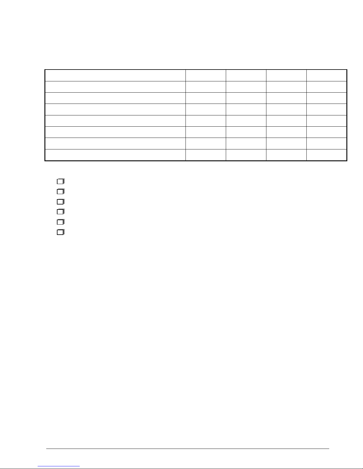
Please fill in the following table :
Excellent Good Fairly good Passable
Easy to find the required information
Clarity of information provided
Quality and accuracy of information given
Document outline
Document presentation and appearance
Quality of illustrations
General satisfaction
Do you think this document could be improved ? if so, how ? :
Improve the overall view
Improve the table of contents
Improve the structure
Add illustrations
Add details
Add information
Comments : ___________________________________________________________________________
_____________________________________________________________________________________
___________________________________________
Would you like to discuss the problems mentioned in this questionnaire? If so, state :
Name of the person to be contacted : ________________________ Phone : ________________
Company : _____________________________________________ Date : _________________
Address : ________________________________________________________________
THANK YOU FOR PARTICIPATING IN THIS ENQUIRY. YOUR COMMENTS WILL HELP US CONTINUE
TO IMPROVE THE QUALITY OF OUR DOCUMENTATION AND THUS BETTER SATISFY YOUR
NEEDS.
When you have filled in this questionnaire, please send it :
-by fax, to +33 (0) 1 30 30 17 86
-by mail, to SAGEM S.A.
Support Service Client / URD 38
2 rue du petit Albi
BP 8250
95 801 Cergy Saint-Christophe

Technical Site Documentation - GSM 900 / 1800 myX-3 & myX-5
Ref. SCT U38 SSC DTS 009 – Index B - December 12 , 2002 Page 2-5
CHAPTER 2 - DESCRIPTION - OPERATION
2.1 REMINDERS ABOUT THE GENERAL CHARACTERISTICS OF GSM, (900 et 1800) AND PCS
(GSM 1900) NETWORKS
Table 1 below gives the characteristics of the radio interface for the GSM 900, GSM 1800 and GSM 1900
systems :
GSM 900 GSM 1800 PCS 1900
Frequency Band (MHz) 890 - 915
925 - 960
1710 - 1785
1805 - 1880
1850 - 1910
1930 - 1990
Number of time intervals per TDMA
frame 8
Width 2 x W simplex (MHz) 2 x 25 2 x 75 2 x 60
Duplex spacing (MHz) 45 95 80
Modulation speed (kbit/s) 271
Speech throughput (kbit/s) 13 (5,6)
Maximum data throughput (kbit/s) 12
Multiple access Frequency and temporal multiplexing / frequency duplexing
Cell radius (km) 0,3 to 30 0,1 to 4 0,1 to 4
SAGEM terminal power (W) 2 1 1
Table 1 : Radio Interface
Table 2 shows powers as a function of the network :
GSM 900 GSM 1800 PCS 1900
Class
number Maximum
nominal
power (W)
Allowable
interval (W) Maximum
nominal
power (W)
Allowable
interval (W) Maximum
nominal
power (W)
Allowable
interval (W)
1 - - 1 [0,63 ; 1,6] 1
2 8 [5,0 ; 12,7] 0,25 [0,16 ; 0,4] 0,25
3 5 [3,2 ; 7,9] 4 [2,5 ; 6,3] 2
4 2 [1,3 ; 3,2]
5 0,8 [0,5 ; 1,3]
Table 2: Terminals power class

Technical Site Documentation - GSM 900 / 1800 myX-3 & myX-5
Ref. SCT U38 SSC DTS 009 – Index B - December 12 , 2002 Page 2-6
Table 3 shows power classes :
Class 1 Class 2 Class 3 Class 4 Class 5
900
43 dBm 39 dBm 37 dBm 33 dBm 29 dBm
1800
30 dBm 24 dBm 36 dBm - -
1900
30 dBm 24 dBm 33 dBm - -
Table 3: RF power classes
Technical Site Documentation - GSM 900 / 1800 myX-3 & myX-5
Ref. SCT U38 SSC DTS 009 – Index B - December 12 , 2002 Page 2-7
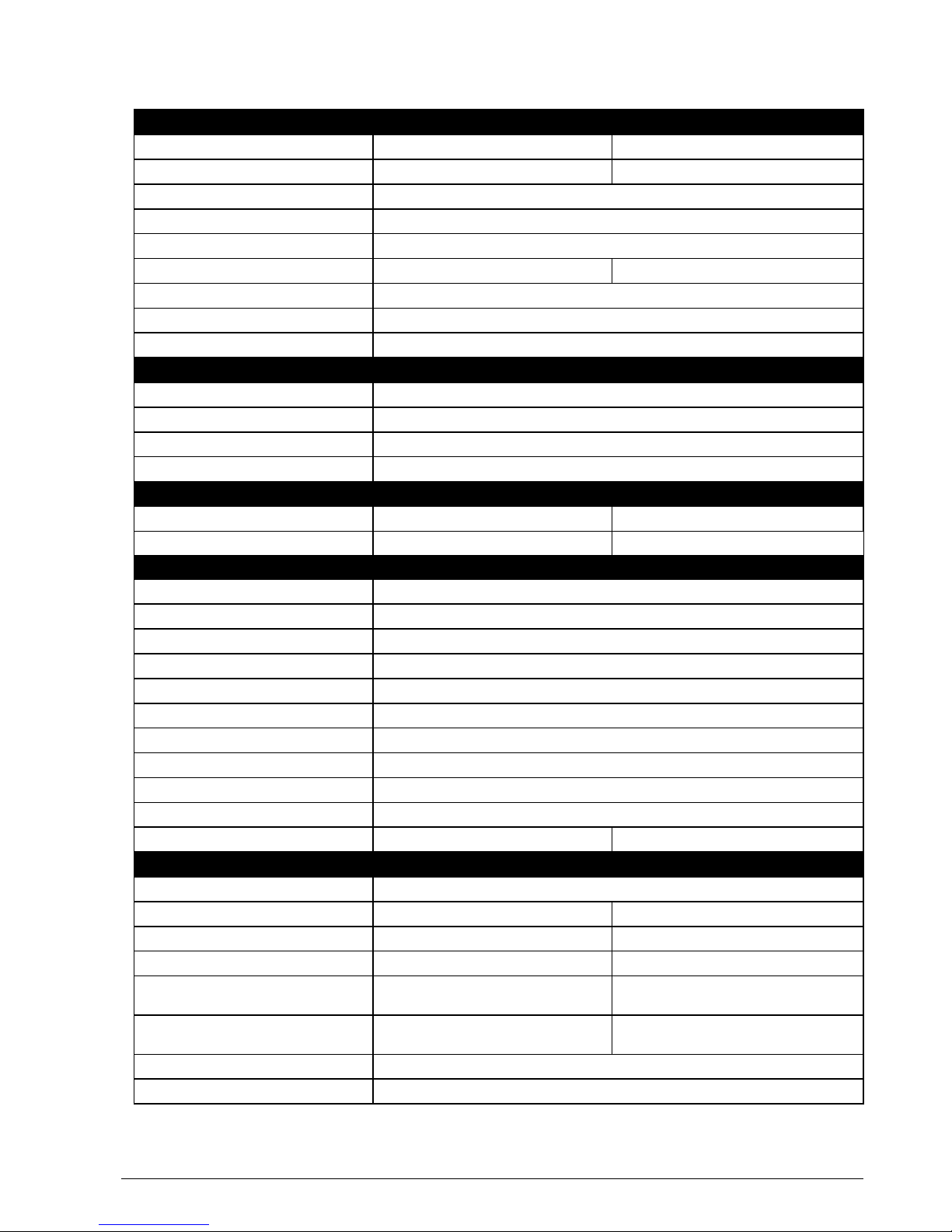
2.2 REMINDERS ABOUT THE CHARACTERISTICS AND OPTIONS OF myX-3 & myX-5 MOBILES
GENERAL CHARACTERISTICS myX-3 myX-3d myX-5 myX-5d
Weight (in g) : 92 92
Dimensions (in mm) : 106*46*20 105*46*20
Volume (cm3) 77
Standby (h) : 240
Talk time (h/mn) : 4
Screen size (pixels), Colour, Back light : Black & White , Blue backlight 101*80 in 256 colours
Line / character number of the screen : 8 lines
Battery Type Li Ion
Recharge Time 2h30
RADIO CAPACITY
GSM 900, 1800 - EGSM Yes
GSM 1900 No (PCS range)
GPRS and type (2+1 / 3+1….) 3+1 ciphering
Voice Quality FR, HR, EFR
COSMETIC
Painted 6 choices Stainless Steel
Keypad Metallic Metallic
USEFUL FEATURES
WAP (1,1 / 1,2…) 1,2
Built in Hands Free Yes
Vibrating device - Silent Mode Yes
Alarm / Clock Yes
Direct access keys ( ADN / SMS / WAP) Yes
SMS notification Yes
Predictive input (Y/N + type) Yes (T9)
Voice commands No
Bis (number) 20
EMS Yes (R5)
MMS No Option
ENTERTAINMENT / FUN FACTS
Mservices Yes
Animated Screensaver Up to 5 (downloadable through DF*) Up to 5 (downloadable through DF*)
Wallpaper or fix screensaver No Up to 30 (downloadable through DF*)
Icons Up to 45 (downloadable through DF*) Up to 50 (downloadable through DF*)
Polyphonic ringtone / number of tones Up to 65 / 8 tones (downloadable through
DF*) Up to 80 / 8 tones (downloadable through
DF*)
Games :nb , download 2 embedded + 1 download (In Fusio in
option) Up to 2 (In Fusio in option)
Java Partially
Interchangeable covers Yes (front&back)
Technical Site Documentation - GSM 900 / 1800 myX-3 & myX-5
Ref. SCT U38 SSC DTS 009 – Index B - December 12 , 2002 Page 2-8
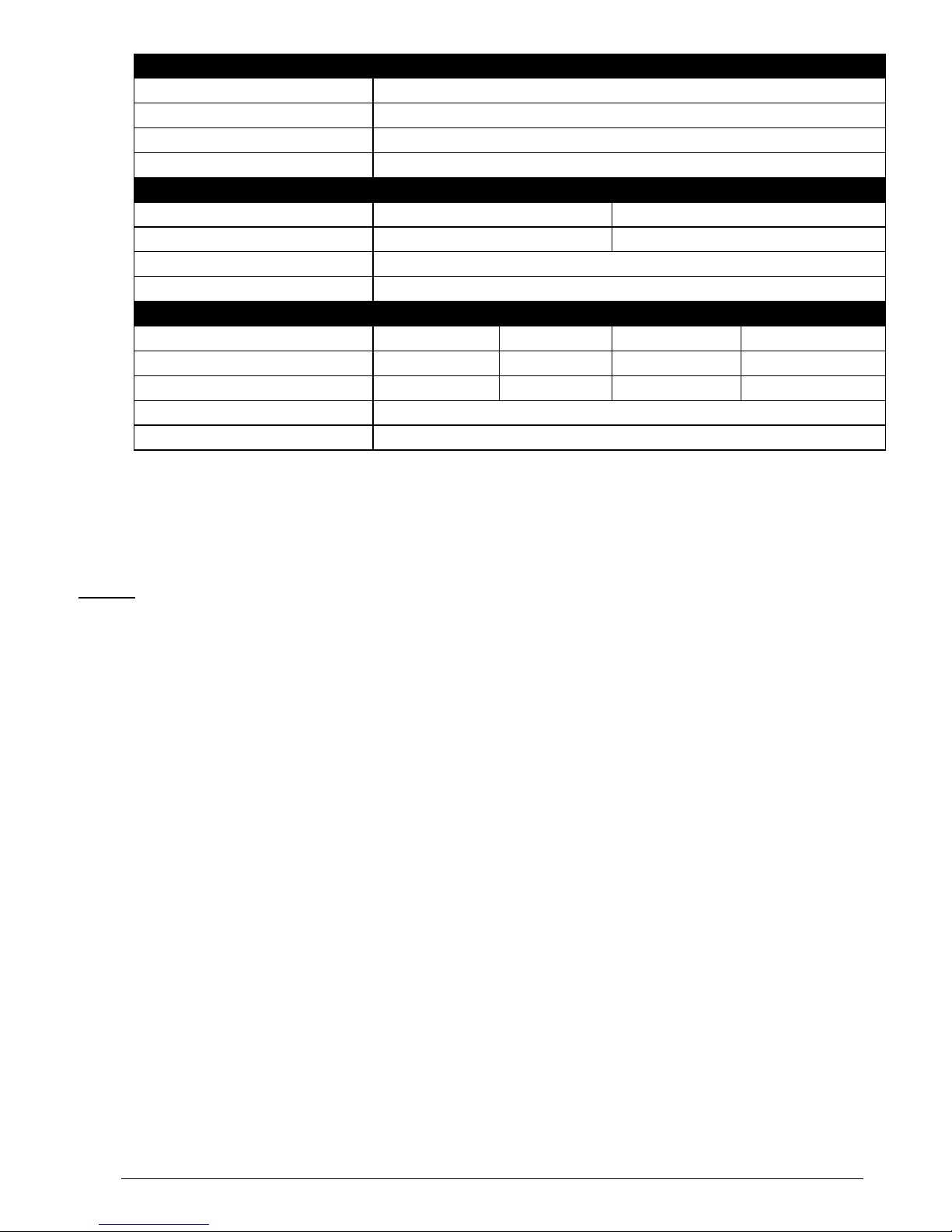
MULTIMEDIA myX-3 myX-3d myX-5 MyX-5d
Picture formats bmp, jpeg, png, gif
Audio formats iMelody1.2, Midi, Wave
Music file reproduction No possibility to forward a polyphonic tone
Integrated still picture camera No
MEMORY
Internal Phone Book (positions) up to 250 up to 300
Internal SMS Memory (positions) up to 50 up to 100
Redial List / Notebook (positions) up to 20
Additional Memory No
DATA TRANSMISSION
IRDA No Yes Yes Yes
Integrated modem No Yes No Yes
Fax application No Yes No Yes
Bluetooth (integrated / add-on) No
e-mail client No
•Download Fun service
Remark : This information is given for guidance , and is in no way contractual characteristics vary according to
customers and countries.

Technical Site Documentation - GSM 900 / 1800 myX-3 & myX-5
Ref. SCT U38 SSC DTS 009 – Index B - December 12 , 2002 Page 2-9
2.3 SMK CONNECTOR
2.3.1 Connector description
This connector is located at the bottom of the transmission module and enable the connection to various
accessories. It comprises power supply pins and signals.
2.3.2 Signal description
SYMBOL PIN
CONNECTOR
No.
SIGNAL FUNCTION NATURE
E/S, Al, Ana
CHARGEUR 1 Phone set power ON and power supply signal. POWER SUPPLY
VBAT 2 POWER SUPPLY IMAGE VOLTAGE, connect
this signal to «CHARGER» (pin n°1) to switch
the module on.
POWER SUPPLY
OUTPUT
ON* 3 SIGNAL RESERVED FOR USE BY SAGEM
(car handsfree kit). OPEN DRAIN
OUTPUT
VPP 4 Flash programming voltage POWER SUPPLY
SDAI2C 5 DATA SIGNAL RESERVED FOR SAGEM
SPECIFIC ACCESSORIES. LOGICAL
INPUT/OUTPUT
GND 6 ZERO VOLT SIGNAL GROUND
SCLI2C 7 CLOCK SIGNAL RESERVED FOR SAGEM
SPECIFIC ACCESSORIES. OPEN DRAIN
INPUT/OUTPUT
INTI2C 8 INTERRUPT SIGNAL RESERVED FOR
SAGEM SPECIFIC ACCESSORIES. LOGICAL INPUT
POLANT32 9 APPLICATION INPUT SERIAL N°2 LOGICAL INPUT
118
Connector
SMK

Technical Site Documentation - GSM 900 / 1800 myX-3 & myX-5
Ref. SCT U38 SSC DTS 009 – Index B - December 12 , 2002 Page 2-10
(RXD2)
RXDG 10 SERIAL DATA TO BE TRANSMITTED. LOGICAL INPUT
TXDG 11 SERIAL DATA RECEIVED. LOGICAL OUTPUT

Technical Site Documentation - GSM 900 / 1800 myX-3 & myX-5
Ref. SCT U38 SSC DTS 009 – Index B - December 12 , 2002 Page 2-11
SYMBOL PIN
CONNECTOR
No.
SIGNAL FUNCTION NATURE
E/S, Al; Ana
DIN32 12 RESET LOGICAL INPUT
ITDATA 13 Interruption signal keep for SAGEM
accessories. LOGICAL INPUT
GND 14 ZERO VOLT. SIGNAL GROUND
BFRXP 15 Audio frequency signal received (φ0). ANALOG OUTPUT
BFRXN 16 Complementary output to BFRXP (φ180). ANALOG OUTPUT
BFTXN 17 AUDIO FREQUENCY SIGNAL TO BE
TRANSMITTED φ180.
Complementary input to BFTXP.
ANALOG INPUT
BFTXP 18 AUDIO FREQUENCY SIGNAL TO BE
TRANSMITTED φ0.
Acoustic L.F. signal to be transmitted.
ANALOG INPUT

Technical Site Documentation - GSM 900 / 1800 myX-3 & myX-5
Ref. SCT U38 SSC DTS 009 – Index B - December 12 , 2002 Page 2-12
2.4 IDENTIFICATION
All phones are identified with an identification label sticked on the antenna.
2.4.1 Illustration
2.4.2 Description
a : IMEI (bar code),
b : IMEI (15 characters)
c : Reference of product / aesthetic used .
d : Sim card Indication (Sim 3V…),
e : Production area Indication,
f : Date code + Production level,
Ex. F260/02 = (F) fabrication area (F : Fougères), (260) day of year, (02) last digit of year
(02→2002).
g : Logo and agreement.
h : Product designation
2.4.3 Description after repair
A new sticker is positioning by Repairing Centre on the antenna :
This extra line will appear if the mobile has already been repaired.
-CRA XXX N°of CRA,
-260/02 Date of repair: (260) repairing day, (02) last digit of year (02→2002).

Technical Site Documentation - GSM 900 / 1800 myX-3 & myX-5
Ref. SCT U38 SSC DTS 009 – Index B - December 12 , 2002 Page 2-13
2.5 PHONE BLOCK DIAGRAM
2.5.1 myX-3 & myX-5 block diagram
2.5.2 Standards and environment
The phone complies with the following standards.
−GSM GT01 V4.4.0
−EN 301 489-1 / EN 301 489-7
−EN 60950 , 73/23/CEE
2.6 EQUIPEMENTS
The description and operation of SAGEM myX-3 & myX-5 are given in the "User’s handbook" supplied with
the handset. This chapter only describes equipment that operates with the myX-3 & myX-5 handset .
LCD / KEYPAD
BASEBAND RADIO

Technical Site Documentation - GSM 900 / 1800 myX-3 & myX-5
Ref. SCT U38 SSC DTS 009 – Index B - December 12 , 2002 Page 2-14
2.6.1 Battery packs
2.6.1.1 Characteristics
Type Technology Weight Voltage capacity
L720 Li-Ion 21 g 3,6 V / 720 mA/H
2.6.1.2 Description
Li-ion type batteries are used. They are rechargeable using:
-mains power supply modules,
-12 V / 24 V, cigar lighter chargers,
-car handsfree kits (compact and comfort),
-Power supply data.
Batteries caution use:
•Store the batteries in a dry and cool place (excessive cold and heat damage the batteries
reliability).
•They must never be stored in bulk, even the rejects, to avoid any short circuits.
•Do not dismantle the battery packs. (Li-Ion regulations).
•Only use original mains power supply module.
Over view
Other manuals for My X-5
3
This manual suits for next models
1
Table of contents
Other Sagem Cell Phone manuals

Sagem
Sagem MY850V Crystal User manual

Sagem
Sagem MYH-10 Series User manual

Sagem
Sagem MY 302X User manual

Sagem
Sagem MYW7 User manual

Sagem
Sagem MY401V User manual

Sagem
Sagem MY501C User manual

Sagem
Sagem MY 302X User manual

Sagem
Sagem MY200X User manual

Sagem
Sagem PW 302X User manual

Sagem
Sagem MY511X User manual

Sagem
Sagem MYMOVIEBOX User manual

Sagem
Sagem MYX5-2 User manual

Sagem
Sagem MY901C User manual

Sagem
Sagem MY850V Crystal User manual

Sagem
Sagem My-X2a User manual

Sagem
Sagem MY401Z User manual

Sagem
Sagem myC5-2 User manual

Sagem
Sagem MY810X User manual

Sagem
Sagem myX-6 Guide

Sagem
Sagem MC-300 Series User manual


