VERS. 2017.06.21 CM 501 ME_MAN_EN
10
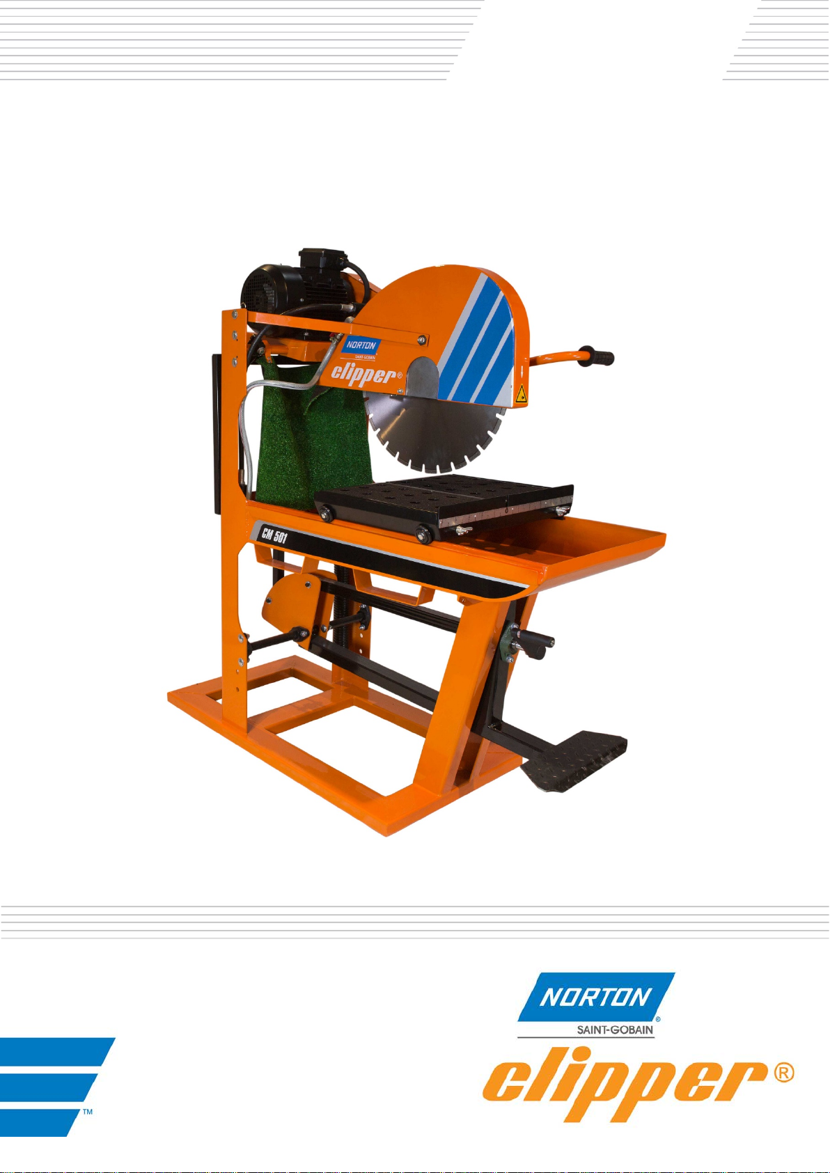
Frame (1)
The jig-welded, reinforced and all-steel construction, diagonally braced to ensure perfect rigidity.
The frame includes a large capacity, sloping water tray with drain plug. Frame has built-in fork lift
brackets (7) for easy transportation. The large base ensures stability while used.
Cutting head (2)
Jig-welded, steel console equipped with pivot bar, which is fixed to frame uprights. Console
supports the electric motor and switch (10), the belt drive with its guard (4), the blade shaft
assembly and the stay level blade guard (3). The balancing of the cutting head is achieved using a
heavy-duty spring. Bearings are machined for perfect fit and alignment.
Blade guard (3)
Jig-welded steel construction with stay level arm and 500mm-diameter blade capacity, which offers
maximum operator protection and increased visibility of the work piece.
Incorporated in the blade guard is a shaft vent cover, which can be easily hinged opened. This
allows easy access to shaft for inspection and blade replacement when motor is switched off, while
fully protecting the blade when in operation.
Down feed and cutting depth adjustment
The spring-loaded cutting head, activated by hand with the grip on the blade guard or with the foot
pedal (5), ensures smooth lowering of the cutting head for shock-free penetration of the work piece
and improved control of the cutting pressure.
A crank assembly (6) in conjunction with a depth locking device on the cutting head pivoting bar
enables the operator to set the cutting head to desired maximum cutting depth.
Conveyor cart (8)
Large, heavy-duty conveyor cart fitted with water flow-control vents, mounted on 4 rollers to give
maximum stability and smooth movement. The conveyor cart is equipped with graduated scale on
the backstop and with a guide-a-cut device.
Water cooling system (9)
The coolant system comprises:
•A powerful, submersible mechanical water pump.
•Plastic suction pipe delivering the water from the water pan to the cutting head.
•A large capacity water pan supplied with drain plug.
•A water-tap, fitted to the blade guard, permitting controlled water flow.
•Two water nozzles located inside the blade guard ensure adequate flow of water to both sides of
the cutting blade.
•A water curtain, fixed to head pivoting bar restricts water spray and minimises water loss.