SAINT-GOBAIN NORTON Clipper CWM 216 User manual

CWM 216 / 254
OPERATING INSTRUCTIONS
Translation of the original instructions

VERS. 04.12.2019 MAN CWM 216/254 EN
2

VERS. 04.12.2019 MAN CWM 216/254 EN
3
The undersigned manufacturer:
SAINT - GOBAIN ABRASIVES S.A.
190, BD J.F. KENNEDY
L- 4930 BASCHARAGE
Declares that this product:
Mitre Saws: CWM 216 230V Code: 70184608463
CWM 254 230V 70184608464
is in conformity with the following Directives:
"MACHINES" 2006/42/CE
"LOW VOLTAGE" 2006/95/CE
"ÉLECTROMAGNÉTIC COMPATIBILITY" 2004/108/CE
"NOISE" 2000/14/CE
and European standard:
EN 61029-1 :2009/A11:2010
EN 61029-2-9:/2012/A11:2013
Valid for machines as of serial number: 4502790460
Storage site for the technical documents:
Saint-Gobain Abrasives 190, Bd. J. F. Kennedy 4930 BASCHARAGE, LUXEMBOURG
This declaration of conformity loses its validity when the product is converted or modified without
agreement.
Bascharage, Luxembourg, 04.12.2019
François Chianese, executive officer.
Declaration of conformity

VERS. 04.12.2019 MAN CWM 216/254 EN
4

VERS. 04.12.2019 MAN CWM 216/254 EN
5
CWM 216/254
OPERATING INSTRUCTIONS
TABLE OF CONTENTS
1BASIC SAFETY INSTRUCTIONS 6
1.1 Machine plate 7
1.2 Safety instructions for particular operating phases 8
1.3 Short description 9
1.4 Purpose of use 9
1.5 Layout 9
1.6 Technical data 18
1.7 Statement regarding noise emission 18
1.8 Electrical connections 18
1.9 Starting the machine 18
2TRANSPORT AND STORING 19
2.1 Securing for transport 19
2.2 Storing of the machine 19
3OPERATING THE MACHINE 20
3.1 Installation 20
3.2 Maintenance 20
4BREAKDOWN –CAUSES AND CURES 21
4.1 Breakdown-finding procedures 21
4.2 Trouble-shooting guide 21
4.3 Customer service 22
4.4 Spare parts 23
4.5 Recycling and disposal 23

VERS. 04.12.2019 MAN CWM 216/254 EN
6
1 BASIC SAFETY INSTRUCTIONS
The CWM 216/254 are Professional sliding miter saws for cutting work pieces such as areas of laminate, parquet,
decking and floor boards as well as for furniture construction parts in non-ferrous materials.
Symbols
Important warnings and pieces of advice are indicated on the machine using symbols. The following symbols
are used on the machine:
Read operator's instructions
Ear protection must be worn
Hand protection must be worn
Eye protection shall be worn
Wear a dust mask
Danger : keep your hands away
Danger : Laser Radiation

VERS. 04.12.2019 MAN CWM 216/254 EN
7
1.1 Machine plate
Important data can be found on the following plate located on the machine:
Machine Model
Machine Code
Maximum blade diameter
and bore size
Serial number
Power
Electrical Insulation Class II
Blade speed
Recycling instruction

VERS. 04.12.2019 MAN CWM 216/254 EN
8
1.2 Safety instructions for particular operating phases
Before commencing work
Before commencing work, make yourself familiar with the working environment at the place of use. The
working environment includes: obstacles in the area of work and manoeuvre, the firmness of the floor,
necessary protection at the site relating to public thoroughfares and the availability of help in the event
of accidents.
Check for correct mounting of the blade regularly.
Immediately remove damaged or badly worn blades, as they endanger the operator whilst rotating.
Only fit NORTON blades to the machine! The use of other tools can damage the machine!
Please wear safety goggles and a dust mask to minimize the effects of dust.
For security reasons, never leave the machine unattended, untied or unlocked.
While the motor running
Do not move the machine whilst the blade is idling.
Always cut with the blade guard in position.
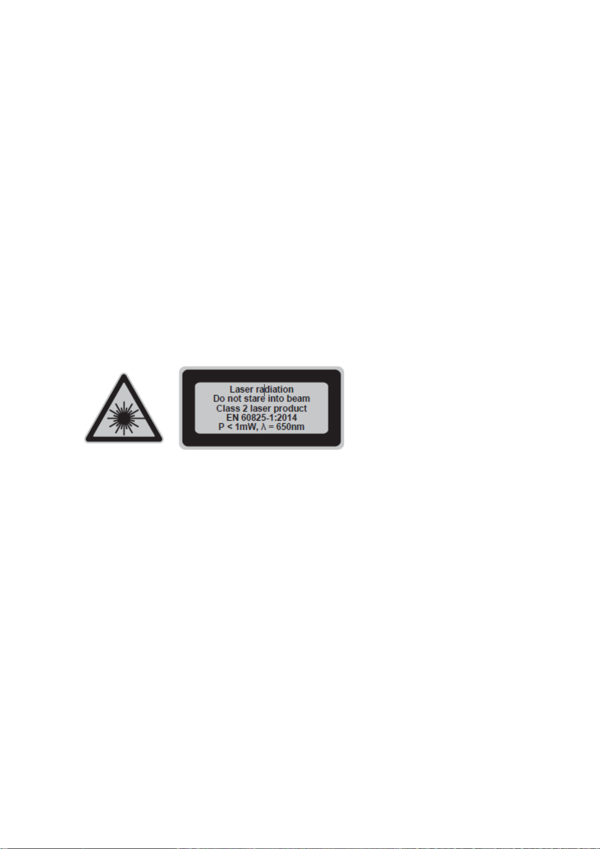
SAFETY INSTRUCTIONS FOR LASER
a) Do not stare directly at the laser beam. A hazard may exist if you deliberately stare into the beam.
b) The laser shall be used and maintained in accordance with the manufacturer’s instructions.
c) Never aim the beam at any person or an object other than the work piece.
d) The laser beam shall not be deliberately aimed at another person and shall be
prevented from being directed towards the eye of a person for longer than 0.25 seconds.
e) Always ensure the laser beam is aimed at a study work piece without reflective surfaces, e.g. wood or
rough coated surfaces are acceptable. Bright shiny reflective sheet or similar is not suitable for laser
applications as the reflective surface may direct the laser beam back at the operator.
f) Do not change the laser device with a different type. Repairs must be carried out by the manufacturer or
an authorized agent.
g) CAUTION: result in hazardous radiation exposure.

VERS. 04.12.2019 MAN CWM 216/254 EN
9
MACHINES DESCRIPTION
Any modification, which could lead to a change in the original characteristics of the machine, may be done
only by Saint-Gobain Abrasives who shall confirm that the machine is still in conformity with the safety
regulations.
1.3 Short description
The CWM 216/254 miter saws are designed for durability and high performance for onsite dry cutting
operations of a wide range of wood and aluminium products. It can be used on construction or industrial site.
Combined with NORTON Wood or aluminium blades, it offers high performance and quality cuts of materials
used in construction. The machine and its component parts are assembled to high standards assuring long
life and minimum maintenance.
1.4 Purpose of use
The CWM 216/254 are intended as a stationary machine for making straight lengthways and crossways cuts
in wood and materials that are similar to wood (e. g. plywood, Product. DF and chipboard).
This product should notbe usedon othermaterials or those harmfulto health.It is to be used for dryoperation
only without water or other cooling liquids. Observe all the instructions therein.
1.5 Layout

VERS. 04.12.2019 MAN CWM 216/254 EN
10

VERS. 04.12.2019 MAN CWM 216/254 EN
11
Operating position (fig A)
1. Push the operating handle (1) (step 1) downwards and disengage the locking bolt (24) from its locking position (step
2).
2. Lift the operating handle (1) to its full height (step 3).
Work piece Clamp (fig B)
The work piece clamp (11) is pre-assembled. Insert the height adjustment pillar (11b) into the work piece
clamp holder (38) on either side of the base if necessary.
Fence (fig C)
Install:
1. Unlock the fence locking lever (37) (step 1).
2. Align the fence gaps (13a) with the screws (37a). Insert the fence (13) into the slot (step 2).
3. Slide the fence to the desired position (step 3).
4. Lock the fence locking lever (37) (step 4).
Uninstall:
1. Unlock the fence locking lever (37).
2. Slide the fence (13) to the end of the slot and remove it from the slot.

VERS. 04.12.2019 MAN CWM 216/254 EN
12
Replacing saw blade (fig D, E, F)
Follow these steps for replacing a worn or damaged saw blade:
1. Open the lower retractable blade guard (32) by hand to expose the locking screw (33a) of the guard
mounting plate (33) (Fig. D step 1).
2. Loosen the locking screw (33a) with the provided multi tool (7) (Fig. D step 2) until the guard mounting
plate (33) can be slid to the side (Fig. D step 3). For the Sliding Miter Saw, press down the operating
handle (1) to help sliding.
3. Press the spindle locking button (26) fully and hold it in position. (Fig. E)
4. Turn the clamping screw (34a) slightly with the provided multi tool until the spindle is locked.
5. Loosen the clamping screw (34a) clockwise and remove it together with the washer the spindle (34d)
(Fig. F).
6. Place a new saw blade on the spindle and make sure that the bore of the saw guard (30).
7. Secure the saw (34) with the outer flange (34c) washer(34b) and clamping screw (34a).
Tighten the clamping screw anti-clockwise with the provided multi tool while the spindle locking button (26)
is pressed.
8. Turn the saw blade (34) by hand to test if it is rotating smoothly .IT should no flutter.
9. Push the lower retractable blade guard to slide the guard mounting plate (33) downward and tighten the
locking screw (33a) with the provided multi tool.
10. Close the lower retractable blade guard (32) afterwards.

VERS. 04.12.2019 MAN CWM 216/254 EN
13
Bench mounting
There are 4 mounting holes (12) at each corner of the base (39) to facilitate bench mounting.
1. Place the miter saw over the workbench tabletop and mark four locations on top of the workbench that
correspond to the mounting hole positions.
2. Drill four mounting holes (Ø 11 mm) at the marked location of the workbench.
3. Place the miter saw on the workbench and align the mounting holes of the base with the drilled holes in
the workbench.
4. Firmly secure the miter saw to the bench surface with 4 bolts (not provided).
5. Carefully check the workbench after mounting to make sure that no movement can occur during use. If
any tipping, sliding, or other movement is noted, secure the workbench to the floor before operating.
Dust Extraction (fig G, H, I)
The product can be used with the dust collection bag (5) or an external dust extraction device.
Dust collection Bag
1. Attach the dust collection bag (5) to the dust extraction outlet (41) (Fig. G).
2. Pull the dust collection bag off to remove it from the appliance.
3. To empty the dust collection box, open the bag by pulling out the sealing slot (5a) (Fig. H).
External dust extraction device
Attach a proper dust extraction device, e.g. a suitable vacuum cleaner attachment (Ø 35 mm) to the dust
extraction outlet (41) (Fig. I).
Adjusting mitre angle (fig J, K)
1. Unlock the turntable locking handle (20) (Fig. J step 1).
2. Press the miter angle adjustment lever (21) downward and hold it in positon (Fig. J step 2).
3. Hold the turntable locking handle (20) and rotate the turntable (23) until the miter angle pointer (16a)
aligns with the desired angle on the miter scale (16) (Fig. J step 3). Release the miter angle adjustment
lever (21).
4. Press down to lock the turntable locking handle (20) (Fig. J step 4).
There are default adjustment positions for the miter angle at 0°, ±15°,
±22.5°, ±31.6° and ±45°.
The miter angle adjustment lever (21) can be locked at pressed position for
convenience.
1. Press the miter angle adjustment lever (21) downward and hold it in position (Fig.K step 1).

VERS. 04.12.2019 MAN CWM 216/254 EN
14
2. Push the miter angle adjustment lever locking knob (18) left to lock the lever (Fig.K step 2).
3. Press the miter angle adjustment lever (21) downward again to release the locking knob (18) (Fig. K step
3).
Adjusting mitre bevel (fig L)
1. Unlock the bevel angle locking lever (22) (Fig. L step 1).
2. Pull out the bevel angle locking knob (40) to enable the right bevel angle/ bevel angle > 45° if required
(Fig. L step 2). Move the operating handle (1) a little before pulling out the bevel angle locking knob if
necessary.
3. Move the operating handle (1) until the bevel angle pointer (10a) aligns with the desired angle on the
bevel scale (10) (Fig. L step 3).
Always ensure the saw blade does not interfere with the fence or any other parts. Remove the fence if
necessary.
4. Lock the bevel angle locking lever (Fig. L step 4).
Always check the bevel locking handle (22) before working. A loose bevel locking handle may cause
serious injury.
Adjusting mitre bevel (fig M)
Use the depth stop (35a) and adjustment knob (35c) to limit the cutting depth of the saw blade into the work
piece.
1. Push in the depth stop (35a) to cut the work piece with the max. cutting depth.
2. Pull out the depth stop (35a) (step 1).
3. Loosen the locking nut (35b) (step 2).
4. Turn the adjustment knob (35c) clockwise to decrease the cutting depth (e. g. for non-through cutting
operations such as grooving / slotting) (step 3).
5. Turn the adjustment knob (35c) anticlockwise to increase the cutting depth.

VERS. 04.12.2019 MAN CWM 216/254 EN
15
6. Tighten the locking nut (35b) (step 4).
Adjusting slide cutting (fig N)
1. Use slide cutting to saw a work piece that is larger than the maximum cutting length of the saw blade.
2. Loosen the slide locking knob (8) (step 1) to allow the cutting head to slide freely (step 2).
Adjusting extension supporter (fig O)
Use the extension supporter for supporting long work pieces. Use an additional support for extremely long
work pieces if required.
1. Unlock the extension supporter locking lever (15) (step 1).
2. Pull out the extension supporter (14) to desired position (step 2).
3. Pull out the small fence (14a) if necessary (step 3).
4. Lock the extension supporter locking lever (15) (step 4).

VERS. 04.12.2019 MAN CWM 216/254 EN
16
Adjusting fence (fig P)
1. Unlock the fence locking lever (37) (step 1).
2. Slide the fence (13) to desired position (step 2).
3. Lock the fence locking lever (37) (step 3).
Ensure the saw blade does not interfere with the fence by conducting a “dry run” with the cutting head set
to the required bevel and miter angle.
Adjusting work piece clamp (fig Q)
The work piece clamp (11) can be assembled on either side of the base. Use it to support work pieces of
different thickness by adjusting the height of the bracket (11d) and plate (11c).
Ensure the motor housing does not interfere with the clamp while operation with the cutting head set to the
required bevel and miter angle.
1. Loosen the locking knob (11a) (step 1) on the height adjustment pillar (11b) and adjust the bracket (11d)
to the desired height (step 2). Tighten the locking knob to secure the bracket (step 3).
2. Press the locking button (11e) and hold it in position (step 4). Adjust the height of the plate (11c) to the
surface of the work piece (step 5).
3. Rotate the height adjustment knob (11f) clockwise tightly to secure the work piece before operation (step
6).
Add a small scrap piece of thin plywood under the work piece clamp to avoid marking the work piece.

VERS. 04.12.2019 MAN CWM 216/254 EN
17
Switch on/off, Led Light and Laser (fig R,S)
1. Switch the LED light (25) on by pressing the “light” symbol of the LED light switch (2).
2. Switch the LED light off by pressing the “OFF” of the LED light switch.
Use the laser as guide when cutting.
3. Switch the laser (31) on by pressing the “laser” symbol of the laser switch (3).
4. Switch the laser off by pressing the “OFF” of the laser switch.
The laser line should be aligned with the blade cutting path. Readjustment of the laser
shall always be carried out by the manufacturer of the tool or his service organization.
5. Press either the left safety lock button (29) or the right safety lock button (27) down
to unlock the on/off switch (28) (step 1).
6. Press the on/off switch (28) to switch the product on (step 2).
7. Release the on / off switch (28) to switch the product off.

VERS. 04.12.2019 MAN CWM 216/254 EN
18
1.6 Technical data
1.7 Statement regarding noise emission
The sound emission values have been obtained according to the noise test code given in EN 62841-1 and
EN 62841-3-9. The noise for the operator may exceed 80 dB(A) and ear protection measures are
necessary.
1.8 Electrical connections
Check that:
The voltage/phase supply corresponds to the information indicated on the machine.
Available power supply must have ground connection in conformity with safety regulations.
1.9 Starting the machine
To start the machine:
Push the button on the right or left side of the handle with your thumb and press the switch on the inside of
the handle
To stop the machine:
Release the buttons

VERS. 04.12.2019 MAN CWM 216/254 EN
19
2 TRANSPORT AND STORING
2.1 Securing for transport
Before transporting the machine, please follow the following instructions:
Switch the product off and disconnect it from the power supply.
Slide the cutting head fully forwards and tighten the slide locking knob (8) to avoid accidental sliding
movement of the upper part.
Follow the reverse order of “Assembly – Operation position” to set the product at locking position.
Always carry the product by its base and transport handle. Never use the cord for carrying the product.
Protect the product from any heavy impact or strong vibrations which may occur during transportation
in vehicles.
Secure the product to prevent it from slipping or falling over.
2.2 Storing of the machine
Switch the product off and disconnect it from the power supply.
Clean the product with a dry cloth. Use a brush for areas that are hard to reach.
In particular, clean the switches and air vents after every use with a cloth and brush.
Remove stubborn dirt with high pressure air (max. 3 bar).
Check for worn or damaged parts. Replace worn parts as necessary or contact an authorised service
centre for repair before using the product again.
Slide the cutting head fully forwards and tighten the slide locking knob (8) if necessary.
Follow the reserve order of “Assembly – Operation position” to set the product at locking position.
Store the product and its accessories in a dark, dry, frost-free, well-ventilated place.
Always store the product in a place that is inaccessible to children. The ideal storage temperature is
between 10°C and 30°C.
We recommend using the original package for storage or covering the product with a suitable cloth or
enclosure to protect it against dust.

VERS. 04.12.2019 MAN CWM 216/254 EN
20
3 OPERATING THE MACHINE
3.1 Installation
3.1.1 Information concerning the working site
Remove from the site anything, which might hinder the working procedure.
Make sure the site is sufficiently well lit.
Observe manufacturer's conditions for connecting to power supplies.
Place electric cables in such a way that damage is excluded.
Make sure you have a continual adequate view of the working area so you can intervene in the working
process at any time.
Keep other staff out of the area, so you can work safely.
Set the machine on the flat and stable ground.
3.1.2 Space required for operation and maintenance
In order to use and maintain the machine safely and correctly, leave 2 m in front and 1, 5 m around of the
machine.
.
3.2 Maintenance
Your power tool requires no additional lubrication or maintenance.
There are no user serviceable parts in your power tool.
Before and after each use, check the product and accessories (or attachments) for wear and damage. If
required, exchange them for new ones as described in this instruction manual. Observe the technical
requirements.
If the replacement of the supply cord is necessary, this has to be done by the
manufacturer or his agent in order to avoid a safety hazard.
This manual suits for next models
1
Table of contents
Other SAINT-GOBAIN Saw manuals

SAINT-GOBAIN
SAINT-GOBAIN Norton Clipper BLOCKBUSTER BBM307 User manual

SAINT-GOBAIN
SAINT-GOBAIN Norton Clipper CWT 255 User manual

SAINT-GOBAIN
SAINT-GOBAIN NORTON clipper C51 Series User manual

SAINT-GOBAIN
SAINT-GOBAIN NORTON clipper CTC705 User manual

SAINT-GOBAIN
SAINT-GOBAIN Norton Clipper CWT 315 User manual

SAINT-GOBAIN
SAINT-GOBAIN NORTON CLIPPER TR 250 H User manual

SAINT-GOBAIN
SAINT-GOBAIN Norton Clipper CM 401 Series User manual

SAINT-GOBAIN
SAINT-GOBAIN NORTON CLIPPER TT 251 User manual

SAINT-GOBAIN
SAINT-GOBAIN NORTON clipper CSB1 D13 H W Series User manual

SAINT-GOBAIN
SAINT-GOBAIN NORTON CLIPPER CM 501 ME User manual