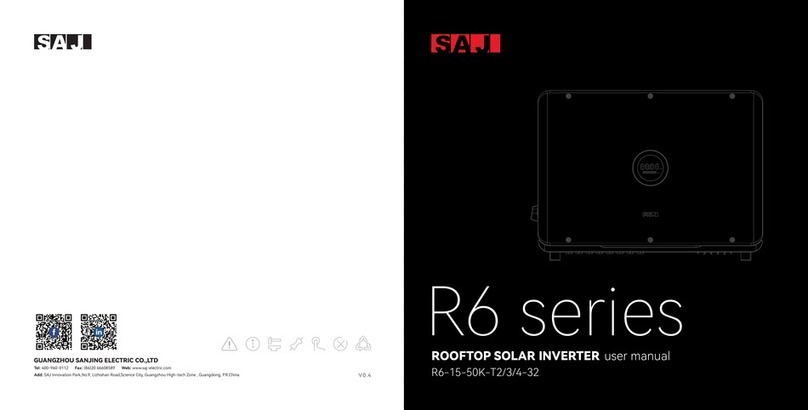
SAJ R6 Series User manual

Tel: 400-960-0112 Fax: (86)20 66608589 Web: www.saj-electric.com
R6 series
user manual
ROOFTOP SOLAR INVERTER
Add: SAJ Innovation Park,No.9, Lizhishan Road,Science City, Guangzhou High-tech Zone , Guangdong, P.R.China.
kW
kWh
GUANGZHOU SANJING ELECTRIC CO.,LTD
V1.0

ROOFTOP SOLAR INVERTER USER MANUAL
kW
kWh

TABLE OF
contents
4. ELECTRICAL CONNECTION----------21
4.1 Safety Instruction -----22
4.2 Specications for Electrical Inteace-----22
4.3 AC Connection-----24
4.4 DC Side Connection-----25
4.5 Communication Connection-----28
5. DEBUGGING INSTRUCTIONS----------29
5.1 Introduction of HMI-----30
5.2.3 Remote Monitoring-----36
1.1 Scope of Application-----02
1.2 Safety-----02
1.2.1 Safety Instruction-----02
1.2.2 Explanations of Symbols-----03
1.2.3 Safety Instructions-----04
2. PRODUCT OVERVIEW ----------05
2.1 Specication for Product Model-----07
2.2 Appearance-----07
2.3 Datasheet-----09
3. INSTALLATION INSTRUCTION----------13
3.1 The Determination of the
Installation Position-----14
3.1.1 Mounting Position-----14
3.2 Mounting Procedure-----16
1. SAFETY PRECAUTIONS ----------01
6. FAULT CODE & Troubleshooting----------37
7. RECYCLING & DISPOSAL----------41
4.3.1 AC Side Electrical Connection-----24
5.2 Monitoring Operation-----31
5.2.1 APP Introduction-----31
5.2.2 Nearby Monitoring-----32

1.1 Scope of
Application
1.2 Safety
1.
SAFETY
precautions
· DANGER indicates a hazardous situation, which, if not avoided, will result in death or serious inju.
· WARNING indicates a hazardous situation, which, if not avoided, can result in death or serious inju or moderate inju.
· CAUTION indicates a hazardous condition, which, if not avoided, can result in minor or moderate inju.
· NOTICE indicates a situation that can result in potential damage, if not avoided.
This User Manual describes instructions and detailed procedures for installing, operating,
maintaining, and troubleshooting of the following SAJ on-grid inveers:
Please keep this manual all time available in case of emergency.
R6-15K-T2-32, R6-17K-T2-32, R6-20K-T2-32, R6-22K-T2-32, R6-25K-T2-32
R6-30K-T3-32, R6-33K-T3-32, R6-36K-T3-32
R6-40K-T4-32, R6-50K-T4-32
DANGER
WARNING
CAUTION
NOTICE
0201
ROOFTOP SOLAR INVERTER INSTRUCTION MANUAL
1.2.1 Safety
Instructions

1.2.2 Explanations of Symbols 1.2.3 Safety Instructions
Symbol
Dangerous electrical voltage
This device is directly connected to public grid, thus all work to the inveer shall only be
carried out by qualied personnel.
Danger to life due to high electrical voltage!
Notice, danger!
This is directly connected with electricity generators and public grid.
Danger of hot suace
An error has occurred
Please go to Chapter 9 “Troubleshooting” to remedy the error.
This device SHALL NOT be disposed of in residential waste
Please go to Chapter 8 “Recycling and Disposal” for proper treatments.
Without Transformer
This inveer does not use transformer for the isolation function.
CE Mark
CQC Mark
No unauthorized peorations or modications
Description
There might be residual currents in inveer because of large capacitors. Wait 5 minutes
before you remove the front lid.
The components inside the inveer will release a lot of heat during operation. Do not
touch metal plate housing during operating.
With CE mark & the inveer fullls the basic requirements of the Guideline Governing
Low-Voltage and Electro-magnetic Compatibility.
The inveer complies with the safety instructions from China's Quality Center.
Any unauthorized peorations or modications are strictly forbidden, if any defect or
damage (device/person) occurred, SAJ shall not take any responsibility for it.
DANGER
· There is possibility of dying due to electrical shock and high voltage.
· Do not touch the operating component of the inveer; it might result in burning or death.
· To prevent risk of electric shock during installation and maintenance, please make sure that all AC and DC terminals
are plugged out.
· Do not touch the suace of the inveer while the housing is wet, otherwise, it might cause electrical shock.
· Do not stay close to the inveer while there are severe weather conditions including storm, lighting, etc.
· Before opening the housing, the SAJ inveer must be disconnected from the grid and PV generator; you must wait for
at least ve minutes to let the energy storage capacitors completely discharged after disconnecting from power source.
· The installation, seice, recycling and disposal of the inveers must be peormed by qualied personnel only in
compliance with national and local standards and regulations.
· Any unauthorized actions including modication of product functionality of any form may cause lethal hazard to the
operator, third paies, the units or their propey. SAJ is not responsible for the loss and these warranty claims.
· The SAJ inveer must only be operated with PV generator. Do not connect any other source of energy to the SAJ inveer.
· Be sure that the PV generator and inveer are well grounded in order to protect propeies and persons.
WARNING
· The solar inveer will become hot during operation. Please do not touch the heat sink or peripheral suace during or
sholy after operation.
· Risk of damage due to improper modications.
CAUTION
· Public utility only.
· The solar inveer is designed to feed AC power directly to the public utility power grid; do not connect AC output of the
inveer to any private AC equipment.
NOTICE
Risk of e l e c tric shoc k ! O n l y
authorized personnel are allowed
to do disassembly, modication or
maintenance. Any resulting defect
or damage (device/person) is not
coverde by SAJ guaranty.
ATTENTION!
03 04
ROOFTOP SOLAR INVERTER INSTRUCTION MANUAL
Figure 2.1
System oveiew
2.
PRODUCT
oveiew
R6 series
R6 Series Solar Inverter
PV Array
On-grid Load
AC Distribution Box Grid
Wi-Fi/ 4G/ Ethernet
05 06
ROOFTOP SOLAR INVERTER INSTRUCTION MANUAL
R6-XK-TX-32 products are grid-tied three phase inveers without transformers, and the
inveers are impoant components of grid-tied solar power systems.
The R6 inveer conves the DC generated by solar panels into AC which is in accordance
with the requirements of public grid and send the AC into the grid, Figure 2.1 shows the
structural diagram of the typical application system.
APP
WebeSolar Poal

2.2 Appearance
2.1 Specication
for Product Model
Figure 2.2
Dimensions of
R6-15K/17K/20K/22K/25K-T2-32
0807
ROOFTOP SOLAR INVERTER INSTRUCTION MANUAL
① R6 represents for product name.
② XK represents rated power XkW of inveer, for example 4K means 4kW.
③ T means three phase; X represents the inveer has the function of X MPP trackers.
④ 32 means that max. DC input current of per MPP tracker is 32A
R6 – XK – TX – 32
① ② ③ ④
kW
kWh
558.0 mm
410.5 mm
234.5mm
Figure 2.3
Dimensions of
R6-30K/33K/36K-T3-32
Figure 2.4
Dimensions of
R6-40K/50K-T4-32
kW
kWh
659.4 mm
473.0 mm
240.0 mm
kW
kWh
659.4 mm
473.0 mm
240.0 mm

2.3 Datasheet
R6-15K-T2-32 R6-17K-T2-32 R6-22K-T2-32 R6-25K-T2-32
1100
180-1000
600
200
32/32
2
2/2
3L+N+PE, 220/380, 230/400, 240/415; 180-280/312-485
50, 60/44-55, 54-65
< 3%
0.8 leading~0.8 lagging
3/3
98.8%
98.5%
Integrated
Integrated
Integrated
Integrated
Integrated
Integrated
Type III
Type III
22500 25500 33000 37500
15000
16500
21.7
25.0
Model
Input (DC)
Max. PV Array Power [Wp]@STC
Max. Input Voltage [V]
MPP Voltage Range [V]
Nominal Input Voltage [V]
Start-up Voltage [V]
Max. Input Current [A]
Number of MPP Trackers
Number of Strings per MPP Tracker
Output (AC)
Rated AC Output Power [W]
Max. AC Output Power [VA] *1
Rated AC Output Current [A]@230Vac
Max. AC Output Current [A]
Nominal AC Voltage/ Range [V]
Nominal AC Grid Frequency/ Range [Hz]
Total Distortion Harmonic [THDi]
Power Factor
Feed-in Phases/AC Connection Phases
Efficiency
Max. Efficiency
Euro Efficiency
Protection
DCI Monitoring
GFCI Monitoring
Grid Monitoring
AC Grounding Detection
AC Short-Circuit Protection
DC Insulation Resistance Detection
DC Surge Protection
AC Surge Protection
R6-15K/17K/20K/22K/25K-T2-32
1009
ROOFTOP SOLAR INVERTER INSTRUCTION MANUAL
17000
18700
24.6
28.4
22000
24200
31.9
36.7
25000
27500
36.2
41.7
20000
22000
29
33.4
R6-20K-T2-32
30000
Model
Anti-islanding Protection
AFCI Protection
Interface
AC Connection
DC Connection
Display
Communication Port
Communication Mode
Load Monitoring
General Data
Topology
Nighttime Power Consumption [W]
Operating Temperature Range
Cooling Method
Ambient Humidity
Max. Operating Altitude [m]
Noise [dBA]
Ingress Protection
Mounting
Dimensions [H*W*D] [mm]
Weight [kg]
Warranty [Year]
Certifications IEC/EN62109-1/2, EN61000-6-1/2/3/4, IEC61683, IEC60068-2, IEC62116, IEC61727,
PEA/MEA, VDE0126-1-1/A1, CEI 0-21, VDE-AR-N 4105, AS/NZS4777.2, CQC NB/T 32004,
G98/G99, NBR 16149, NBR 16150, C10/11, RD1669, UNE206006, UNE206007, EN50438
R6-15K-T2-32 R6-17K-T2-32 R6-22K-T2-32 R6-25K-T2-32R6-20K-T2-32
AFD
Optional
Terminal Block
MC4
LED+APP (Bluetooth)
RS232+RS485 (RJ45)+DRM(RJ45)
Wi-Fi/Ethernet//4G
24/7 (Optional)
Transformerless
<0.6
-40℃~+60℃
intelligent fan Cooling
0%~100% non-condensing
4000m (>3000m power derating)
<50
IP65
Rear Panel
558*410.5*234.5
23.5
5 (Standard)/10/15/20/25 (Optional)

1211
ROOFTOP SOLAR INVERTER INSTRUCTION MANUAL
R6-30K-T3-32 R6-33K-T3-32 R6-40K-T4-32 R6-50K-T4-32
1100
180-1000
600
200
3L+N+PE, 220/380, 230/400, 240/415; 180-280/312-485
50, 60/44-55, 54-65
< 3%
0.8 leading~0.8 lagging
3/3
98.8%
98.5%
Integrated
Integrated
Integrated
Integrated
Integrated
Integrated
Type II
Type III
45000 49500 60000 75000
30000
33000
43.5
50
Model
Input (DC)
Max. PV Array Power [Wp]@STC
Max. Input Voltage [V]
MPP Voltage Range [V]
Nominal Input Voltage [V]
Start-up Voltage [V]
Max. Input Current [A]
Number of MPP Trackers
Number of Strings per MPP Tracker
Output (AC)
Rated AC Output Power [W]
Max. AC Output Power [VA] *1
Rated AC Output Current [A]@230Vac
Max. AC Output Current [A]
Nominal AC Voltage/ Range [V]
Nominal AC Grid Frequency/ Range [Hz]
Total Distortion Harmonic [THDi]
Power Factor
Feed-in Phases/AC Connection Phases
Efficiency
Max. Efficiency
Euro Efficiency
Protection
DCI Monitoring
GFCI Monitoring
Grid Monitoring
AC Grounding Detection
AC Short-Circuit Protection
DC Insulation Resistance Detection
DC Surge Protection
AC Surge Protection
R6-30K/33K/36K-T3-32, R6-40K/50K-T4-32
33000
36300
47.8
55
40000
44000
58
66.7
50000
50000
72.5
75.8
36000
39600
52.2
60
R6-36K-T3-32
54000
32/32/32
3
2/2/2
32/32/32/32
4
2/2/2/2
Model
Anti-islanding Protection
AFCI Protection
Interface
AC Connection
DC Connection
Display
Communication Port
Communication Mode
Load Monitoring
General Data
Topology
Nighttime Power Consumption [W]
Operating Temperature Range
Cooling Method
Ambient Humidity
Max. Operating Altitude [m]
Noise [dBA]
Ingress Protection
Mounting
Dimensions [H*W*D] [mm]
Weight [kg]
Warranty [Year]
Certifications IEC/EN62109-1/2, EN61000-6-1/2/3/4, IEC61683, IEC60068-2, IEC62116, IEC61727,
PEA/MEA, VDE0126-1-1/A1, CEI 0-21, VDE-AR-N 4105, AS/NZS4777.2, CQC NB/T 32004,
G98/G99, NBR 16149, NBR 16150, C10/11, RD1669, UNE206006, UNE206007, EN50438
AFD
Optional
Terminal Block
MC4
LED+APP (Bluetooth)
RS232+RS485 (RJ45)+DRM(RJ45)
Wi-Fi/Ethernet//4G
24/7 (Optional)
Transformerless
<0.6
-40℃~+60℃
intelligent fan Cooling
0%~100% non-condensing
4000m (>3000m power derating)
<50
IP65
Rear Panel
659.4*473*240
5 (Standard)/10/15/20/25 (Optional)
R6-30K-T3-32 R6-33K-T3-32 R6-40K-T4-32 R6-50K-T4-32R6-36K-T3-32
34.5 35.5 36

3.
INSTALLATION
instruction
DANGER
NOTICE
· Dangerous to life due to potential re or electricity shock.
· Do not install the inveer near any inammable or explosive items.
· This inveer will be directly connected with HIGH VOLTAGE power generation device; the installation must be peor
med by qualied personnel only in compliance with national and local standards and regulations.
· This equipment meets the pollution degree II.
· Inappropriate or the harmonized installation environment may jeopardize the life span of the inveer.
· Installation directly exposed under intensive sunlight is not recommended.
· The installation site must be well ventilated.
3.1 The Determination
of the Installation
Position
The equipment employs natural convection cooling, and it can be installed indoor or outdoor.
(1) Do not expose the inveer to direct solar irradiation as this could cause power derating due
to overheating.
Figure 3.1
Mounting Method
Max 15
1413
ROOFTOP SOLAR INVERTER INSTRUCTION MANUAL
3.11 Mounting Position

(2) Mount veically or tilted backwards by max. 15°. Never install the inveer tilted forwards,
sideways, horizontally or upside down.
(3) Install the inveer at eye level for convenience when checking the LCD display and
possible maintenance activities.
(4) When mounting the inveer, please consider the solidness of wall for inveer, including
accessories. Please ensure the Rear Panel mount tightly.
To make sure the installation spot is suitably ventilated, if multiple SAJ on-grid solar inveers
are installed same area.
50CM
Figure 3.2
Minimum Clearance
50CM30CM
50CM50CM
3.2
Mounting
Procedure
(1) Mark the Positions of the Drill Holes of the Rear Panel
The mounting position should be marked as shown in Figure 3.3& Figure 3.4.
Figure 3.3
Dimensions of rear panel of
R6-15K/17K/20K/22K/25K-T2-32
1615
ROOFTOP SOLAR INVERTER INSTRUCTION MANUAL
kW
kWh
110 110 110
20
380
270
74
57
R3
20
4-Φ8
Unit: mm
Figure 3.4
Dimensions of rear panel of
R6-25K/30K/33K-T3-32, R6-36K/40K-T4-32
16
8
477
575.00
210
265

(3) Secure the Screws and the Rear Panel
The panels should be secured onto the mounting position by screws as shown in Figure 3.7.
Figure 3.7
Mount the rear panel
1817
ROOFTOP SOLAR INVERTER INSTRUCTION MANUAL
(2) Drill Holes and Place the Expansion Tubes
Drill 4 holes in the wall (in conformity with position marked in Figure 3.5 & Figure 3.6), and
then place expansion tubes in the holes using a rubber mallet.
Figure 3.5
Drill holes’dimensions of
R6-15K/17K/20K/22K/25K-T2-32
4-Φ8
110 110 110
4-Φ8 110 110 110
185
Figure 3.6
Drill holes’dimensions of
R6-30K/33K/36K-T3-32, R6-40K/50K-T4-32
4-Φ8
477
210
Unit: mm

19
ROOFTOP SOLAR INVERTER INSTRUCTION MANUAL
(4) Mount the Inveer
Carefully mount the inveer to the rear panel as shown in Figure 3.8 and 3.9, Make sure that
the rear pa of the equipment is closely mounted to the rear panel.
Figure 3.8
Mount inveer
Figure 3.9
Fasten the inveer and
hanging panel with screws
kW
kWh
20

4.
ELECTRICAL
NOTICE
4.1
Safety Instruction
connection
4.2
Specications for
Electrical Inteace
Figure 4.1
Electrical inteace of
R6-15K/17K/20K/22K/25K-T2-32
· Dangerous to life due to potential re or electricity shock.
· When power-on, the equipment should in conformity with national rules and regulations.
· The direct connection between the inveer and high voltage power systems must be operated by qualied
technicians in accordance with local and national power grid standards and regulations.
· The PV arrays will produce lethal high voltage when exposed to sunlight.
Electrical connection must only be operated on by professional technicians. Please keep in
mind that the inveer is a bi-power supply equipment. Before connection, necessa
protective equipment must be employed by technicians including insulating gloves, insulating
shoes and safety helmet.
DANGER
· Electrical connection should in conformity with proper stipulations, such as stipulations for cross-sectional area of
conductors, fuse and ground protection.
· The oveoltage catego on DC input po is , on AC output po is .
2221
ROOFTOP SOLAR INVERTER INSTRUCTION MANUAL
ACD FE G
B

23
ROOFTOP SOLAR INVERTER INSTRUCTION MANUAL
Figure 4.2
Electrical inteace of
R6-30K/33K/36K-T3-32
Table 4.1
Specications for inteace
Code
A
B
C
D
E
F
G
Name
DC Switch
Decompression Valves
DC Input
RS232 Communication (GPRS/ Wi-Fi /4G)
Ground Connection
RS485 Communication+DRM
Terminal Block
A C B D E F G
Figure 4.3
Electrical inteace of
R6-40K/50K-T4-32
A C B D E F G
4.3
AC Connection
Type Cross-sectional area of cables(mm²)
10.0-16.0
16.0-35.0
16.0-35.0
Table 4.2
Recommended power grid connecting
cable specication
If the grid-connection distance is too far, please select AC cable with larger diameter as per
the actual condition.
Scope Recommended value
16.0
25.0
25.0
R6-15K/17K/20K/22K/25K-T2-32
R6-30K/33K/36K-T3-32
R6-40K/50K-T4-32
(1)Ground of the inveer. After penetrating the external hex head screw through OT
terminal of the grounding line, screw in the grounding po of enclosure of the inveer in
clockwise direction and make sure it’s screwed up tightly.
Figure 4.4
Inveer ground protection
4.3.1 AC Side
Electrical Connection
24

2625
ROOFTOP SOLAR INVERTER INSTRUCTION MANUAL
(2) Screw o the screws at the AC output wire cover and take out the cover.
Penetrate the AC cable of which the insulation layers has been peeled o through the AC
waterproof locking screw hole of the cover. Lock L1 wire, L2 wire, L3 wire, N wire and PE
wire tightly as per the marked connection positions
on the inteace board.
Figure 4.5
Connect cable
(3) After xing the cover at the AC output wire terminal with screws, tighten up the AC
waterproof nut.
4.4
DC Side Connection
Cross-sectional area of cables(mm²)
Outside diameter of the cables(mm)
Recommended value
4.0
Scope
4.0~6.0
Table 4.3
Recommended specications of DC cables 4.2~5.3
Figure 4.7
Connecting Cables
DC connector is made up of one positive connector and one negative connector
Figure 4.6
Positive and negative connectors
NOTICE
· Please place the connector separately after unpacking in order to avoid confusion for connection of cables.
· Please connect the positive connector to the positive side of the solar panels, and connect the negative connector
to the negative side of the solar side. Be sure to connect them in right position.
Connecting Procedures:
(1) Use specied strip tool to strip the insulated enclosure of the positive and negative cables
with appropriate length (8-10mm).
positive connector
negative connector
8-10mm positive cable
8-10mm negative cable

Figure 4.8
Connect the Inveer
(2) Feed the positive and negative cables into corresponding lock screws and crimp them
tightly with a wire crimper. Make sure that the withdrawal force of the pressed cable is
larger than 400N.
(3) Plug in the pressed positive and negative cables into relevant insulated enclosure, a
“click” sound should be heard when the contact cable assembly is seated correctly.
(4) Fasten the lock screws on positive and negative connectors into corresponding
insulated enclosure and make them tight.
(5) Connect the positive and negative connectors into positive and negative DC input
terminals of the inveer, a “click” sound should be heard when the contact cable assembly
is seated correctly.
NOTICE
· Before inse the connector into DC input terminal of the inveer, please make sure that the DC switch of the
inveer is OFF.
· Please use the original terminal to install.
1. Connection Po
27
1
1
ROOFTOP SOLAR INVERTER INSTRUCTION MANUAL
R6 inveer is standardly equipped with a RS485 inteace and a RS232 inteace.
Figure 4.9
RS485 pin
4.5
Communication
Connection 1 2 3 4 5 6 7 8
Table 4.4
RS485 pin po denition
Pin Number
1
2
3
4
5
6
7
8
Description
NC
GND_W
+7V_W
NC
NC
NC
RS485-A
RS485-B
Eect
Ground wire
Power supply
Transmission RS485 dierential signal
Figure 4.10
RS232 pin
1 2 3 4
Table 4.5
USB pin po denition
Pin Number
1
2
3
4
Description
+7V
RS-232 TX
RS-232 RX
GND
Eect
Power supply
Send data
Receive data
Ground wire
(1) USB inteace could be externally connected with eSolar AIO3 module, for operation in
details please refer to eSolar AIO3 module Quick Installation Guide in www.saj-electric.com
(2) USB inteace could be externally connected with eSolar 4G module, for operation in
details please refer to eSolar 4G module Quick Installation Guide in www.saj-electric.com
(3) USB inteace could be externally connected with eSolar WiFi module, for operation in
details please refer to eSolar WiFi module Quick Installation Guide in www.saj-electric.com
28

5.
DEBUGGING
instructions
Introduction of HMI
(Human-Machine Inteace)
Figure 5.1
Human-Machine Inteace
3029
ROOFTOP SOLAR INVERTER INSTRUCTION MANUAL
5.1

Talbe 5.1
Inteace description
Status
Solid Green
Breathing Mode
Solid Red
Breathing Mode
OFF
Description
Display
3231
ROOFTOP SOLAR INVERTER INSTRUCTION MANUAL
The inveer is in normal on-grid state
The inveer is in the initialization or waiting state
An error occurs
Software is upgrading in the inveer
Power o
Current power (kW) / Error code
Total yield (kWh)
LED Panel 1
LED Panel 2
Ring Light
5.2
Monitoring
Operation
● R6 series products could be monitored through eSolar APP.
● This equipment is standardly equipped with a USB inteace which could transfer
AIO3/4G module (with built-in Bluetooth) and Wi-Fi module to monitor running state of the
equipment.
eSolar could achieve communication with the equipment via Bluetooth, Cellular network and
Wi-Fi and it is an APP for nearby and remote monitoring.
Download APP
Installers using iOS system could search for “eSolar O&M” in App Store and download this App.
Installers using Android system could search for “eSolar O&M” in Google play and download
this App.
For iOS / Android system, Installers could visit SAJ ocial website: www.saj-electric.cn and
scan the QR code to download “eSolar O&M” APP.
Account---Please use the installer account to login.
Note: For the end user, please download and install the “eSolar Air” APP and log in to the APP
or SAJ ocial website to register your account.
5.2.1
APP Introduction
After installing the eSolar AIO3/4G/WiFi module (with built-in Bluetooh) the mobile phone
could be directly connected with the inveer via Bluetooth.
5.2.2
Nearby Monitoring Bluetooth connection
Connection setting
Step 1
Log in eSolar O&M APP. Choose “User” inteace
→ choose “Remote control”.
Step 2 Step 3
Choose connection way as
“Bluetooth” → choose “next step”.
kW h
kW
/

3433
ROOFTOP SOLAR INVERTER INSTRUCTION MANUAL
Step 5
Select the conguration
method of the module
network connection.
Step 6
Connect successfully → set count
and grid code for rst sta-up →
after inveer sta, users can view
inveer’s information.
Step 4
Search for equipment →
click the Bluetooth name
matched with the inveer.
Connection way, running state, basic information, running information, Power information
and events information of the communication of the inveer could be checked.
Equipment information
Step 1: Click “Basic info”
Inveer model, Module SN code, Module rmware
version, Communication board rmware version,
Main board rmware version, Slave board
rmware version could be checked.
Step 2: Click “Running info”
PV information (voltage and current at PV
terminal), Grid power information (voltage, current
and frequency at AC terminal), etc.
Other manuals for R6 Series
5
This manual suits for next models
10
Table of contents
Other SAJ Inverter manuals

SAJ
SAJ Sunfree 4K User manual

SAJ
SAJ AS1-3KS-5.1 User manual

SAJ
SAJ Sununo-TL Series User manual

SAJ
SAJ AS1-3KS-5.1 User manual

SAJ
SAJ 8000m-2SR4GH User manual

SAJ
SAJ Sununo Plus Series User manual

SAJ
SAJ eSolar RS485 User manual

SAJ
SAJ R6 Series User manual

SAJ
SAJ R5-3.6K-S2 User manual

SAJ
SAJ Suntrio-TL Series User manual
Popular Inverter manuals by other brands

Solectria Renewables
Solectria Renewables PVI 15KW Installation and operation manual

Immergas
Immergas CP4 XL/M quick start guide

Polinovel
Polinovel V+ Series product manual

Sungrow
Sungrow SG10KTL-M user manual

BOSSCO
BOSSCO MIG 200 operating manual

FRONIUS
FRONIUS Symo Hybrid 3.0-3-S operating instructions