SAJ Suntrio-TL Series User manual


Preface
Thank you for choosing SAJ solar inverter. We are happy to provide you with rst-class products
and quality service.
The manual includes installation, operation, maintenance, troubleshooting, and safety notice. As
long as you follow the instruction of this manual, you will get the professional guidance and our
wholehearted service.
Customer-orientation is our forever commitment. We hope this “User Manual” become your
good helper in solar power generation.
Please check the latest version at www.saj-solar.com
Guangzhou Sanjing Electric Co., Ltd.

User Manual
Contents
1. Information on this Manual...........................................................................................................................................1
1.1 Validity..............................................................................................................................................................................1
1.2 Target Group..................................................................................................................................................................,1
1.3 Symbols Used................................................................................................................................................................1
2. Safety........................................................................................................................................................................................2
2.1 Intended Use..................................................................................................................................................................2
2.2 Safety Precaution.........................................................................................................................................................2
2.3 Explanations of Symbols on Inverter...............................................................................................................4
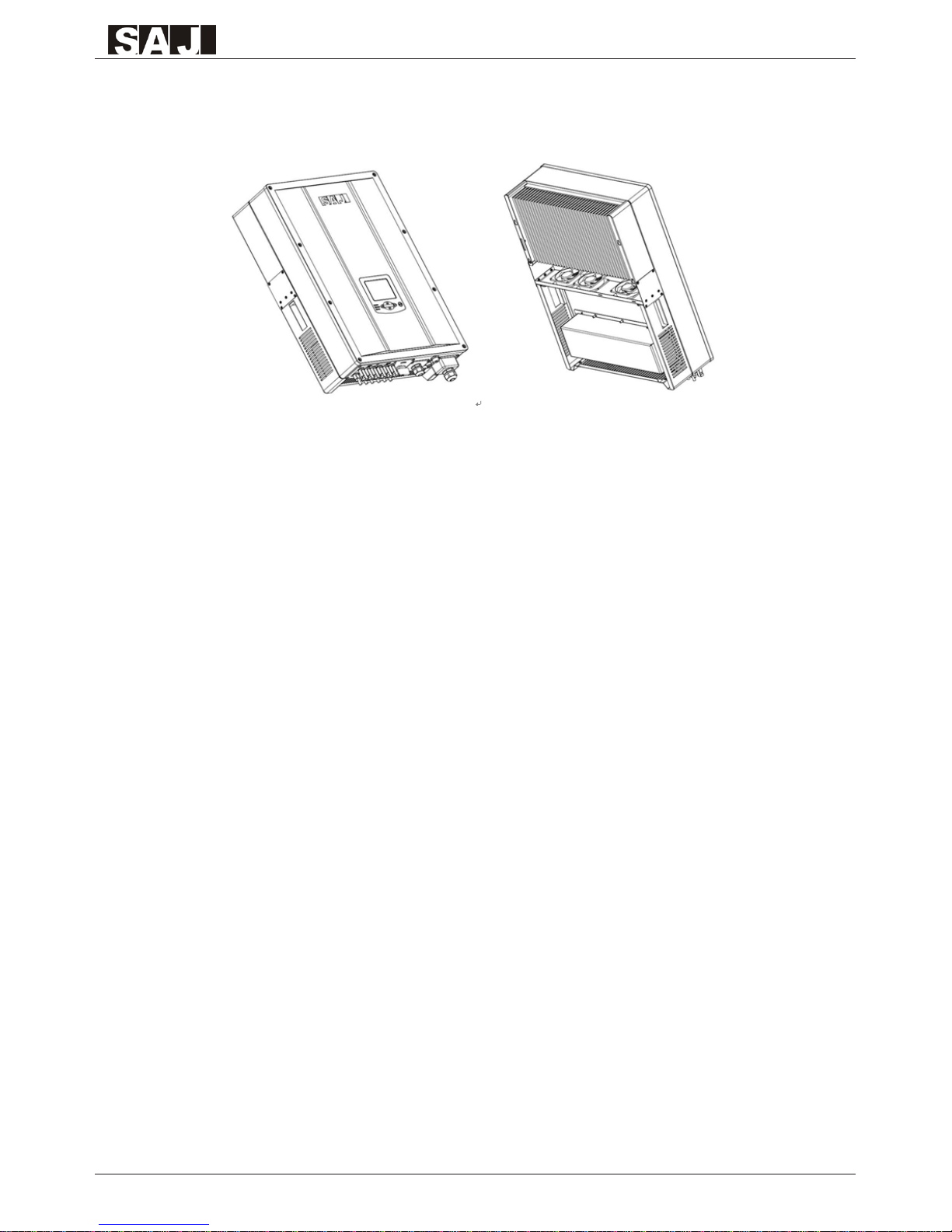
3. Product Overview...............................................................................................................................................................5
3.1 Product Appearance...................................................................................................................................................5
3.2 Major Characteristics.................................................................................................................................................5
3.3 Technical Data...............................................................................................................................................................6
4. Installation Instructions..................................................................................................................................................8
4.1Unpacking.......................................................................................................................................................................8
4.2 Mounting Instructions...............................................................................................................................................9
4.3 Mounting Procedure..............................................................................................................................................11
4.4 Optional Anti-Theft Protection.........................................................................................................................13
5. Electrical Connection....................................................................................................................................................14
5.1 Safety..............................................................................................................................................................................14
5.2 Overview of Connection Area...........................................................................................................................14
5.3 Connection Cables Requirements...................................................................................................................16
5.4 Miniature circuit breaker......................................................................................................................................17
5.5 Connecting the Electricity Grid (AC)............................................................................................................18
5.5.1Conditions for the AC Connection.................................................................................................................18
5.5.2 AC Connection procedure................................................................................................................................18
5.5.3 Connecting the Second Protective Conductor............................................................................................20
5.6 Connecting the PV Array (DC)...........................................................................................................................21
5.6.1 Conditions for DC Connection.......................................................................................................................21
5.6.2 Connection Procedures by H4:.......................................................................................................................22
5.7 Communication and Monitoring Setting......................................................................................................25
5.7.1 Communication through RS485....................................................................................................................25
5.7.2 Communication through Ethernet RJ45......................................................................................................27
5.7.3 Extended Wi-Fi Solution with Wi-Fi Bridge.............................................................................................27
5.7.4 Communication Cable Assembly Instructions...........................................................................................28
6. LCD Operation..................................................................................................................................................................31
6.1 LCD Display Overview..........................................................................................................................................31
6.2 Startup the Inverter...................................................................................................................................................32
6.3 LCD Main Screen......................................................................................................................................................33
6.4 LCD Menu Structure...............................................................................................................................................34
6.4.1 LCD Graph Submenu......................................................................................................................................35
6.4.2 LCD Setting Submenu.....................................................................................................................................36
6.5 Error Report Mechanism and Guidance........................................................................................................43
7. Recycling and Disposal.................................................................................................................................................44
8. Troubleshooting................................................................................................................................................................45
9. Guaranty Service...............................................................................................................................................................50
10. Contact SAJ........................................................................................................................................................................50

User Manual
User Manual
1
1.Information on this Manual
1.1 Validity
This User Manual describes instructions and detailed procedures for installing, operating,
maintaining, and troubleshooting of the following SAJ grid-tie inverters:
Suntrio-TL6K, Suntrio-TL8K, Suntrio-TL10K, Suntrio-TL12K
Suntrio-TL15K, Suntrio-TL17K, Suntrio-TL20K
Please keep this manual where it will be accessible at all times.
1.2 Target Group
This manual is for qualied electrically skilled person, who must strictly perform the tasks follow
this manual.
1.3 Symbols Used
DANGER
DANGER indicates a hazardous situation which, if not avoided, will result in death or
serious injury.
WARNING
WARNING indicates a hazardous situation which, if not avoided, can result in death or
serious injury or moderate injury
CAUTION
CAUTION indicates a hazardous condition which, if not avoided, can result in minor or
moderate injury.
NOTICE
NOTICE indicates a situation that can result in potential damage, if not avoided.

User Manual
2
User Manual
2.Safety
2.1 Intended Use
The Suntrio-TL series inverters are PV inverter which converter the direct current of a PV array
into alternating current and feed this into the electricity grid.
The inverters are designed according to the safety rules. However, improper use, alteration or
modication may cause lethal hazards for the operator or third parties, or may result in damage
to the units and other property. SAJ is not responsible for the loss and invalidate these warranty
claims.
Figure 2.1 Grid-tie Solar System with Suntrio inverter
2.2 Safety Precaution
DANGER
● DANGER due to electrical shock and high voltage
● Do not touch the operating component of the inverter; it might result in burning or death.
● To prevent risk of electric shock during installation and maintenance, please make sure that all AC
and DC terminals are plugged out.
● Do not touch the surface of the inverter while the housing is wet, it might lead to electrical shock.
● Do not stay close to the inverters while there are severe weather conditions including storm, lighting,
etc.
● Before opening the housing, the SAJ inverter must be disconnected from the Grid and PV generator;
you must wait at least five minutes to let the energy storage capacitors fully discharged after
disconnecting from power source.

User Manual
User Manual
User Manual
3
WARNING
● The installation, service, recycling and disposal of the inverters must be performed by qualied
personnel only in compliance with national and local standards and regulations.
● Any unauthorized actions including modification of product functionality of any form
may cause lethal hazard to the operator, third parties, the units or their property. SAJ is not
responsible for the loss and deny these warranty claims.
● Suntrio inverters must only be operated with PV generator. Do not connect any other source of
energy to the inverters.
● Be sure that the PV generator and inverter are well grounded in order to protect properties and
persons.
CAUTION
● The PV inverter will become hot during operation. Please don’t touch the heat sink or
peripheral surface during or shortly after operation.
● Risk of damage due to improper modications.
● Never modify or manipulate the inverter or other components of the system.
NOTICE
● The PV inverter is designed to feed AC power directly to the public utility power
grid; do not connect AC output of the inverter to any private AC equipment.


User Manual
User Manual
User Manual
5
3.Product Overview
3.1 Product Appearance
Figure 3.1 Suntrio inverters Overview
3.2 Major Characteristics
SAJ Suntrio inverter has following characteristics which make SAJ grid-tied solar inverter
“Higher Efciency, High Reliability and Lower Cost”.
Leading technology
• Max. efciency 98.1%
• MPPT accuracy up to 99.9% efciency
User-friendly
• 5 inch LCD display with comprehensive information
• Embedded webserver monitoring
• Easy installation
Flexible
• Multi-country conguration
• RS485 / Ethernet / Wi-Fi communication
• Wide range of DC input voltage
• IP65 for indoor and outdoor

User Manual
6
User Manual
3.3 Technical Data
Type Suntrio-TL6K Suntrio-TL8K Suntrio-TL10K
Input (DC)
Max. DC Power [W] 6300 8200 10400
Max. DC Voltage [V] 1000V
MPPT Voltage Range [V] 240~800 240~800 240~800
Nominal DC Voltage 600
Start Voltage[V] 300
Min. DC Voltage[V] 200
Max. DC input Current PV1 / PV2 [A] 16 / 16
Number of MPPT 2
String(s) per MPPT 2
DC Switch Optional
Output (AC)
Rated AC Power [W](@230V,50Hz) 6000 8000 10000
Max. AC Apparent Power [VA] 6000 8000 10000
Rated AC Current[A] 8.7 11.6 14.5
Max. AC Current [A] 9.7 12.9 15.8
Nominal AC voltage/ range 3/N/PE, 220/380V,230/400V,240/415V;180V-280V/312V-485V
Grid frequency/ range 50Hz,60Hz /44Hz-55Hz,54-65Hz
Total Harmonic Distortion (THDi) < 3%(at nominal power)
Power factor, adjustable 0.9 leading~0.9 lagging
Feed-in Phase / Connection Phase 3 / 3
Efciency
Max. Efciency 97.9% 97.9% 98.0%
Euro Efciency (at 600Vdc)97.3% 97.3% 97.5%
MPPT Accuracy >99.5%
Protection
Internal Overvoltage Protection Integrated
DC Insulation Monitoring Integrated
DCI Monitoring Integrated
GFCI Monitoring Integrated
Grid Monitoring Integrated
AC Short Circuit Current Protection Integrated
Thermal Protection Integrated
Anti-island protection monitoring AFD
Interface
DC Connection H4/MC4
LCD Display Graphic LCD Display, Backlight, Inverter Parameter and Data Display
Display Language Multi Language
Datalogger & Communication RS485,Ethernet(Webserver embedded), WiFi(Optional),
Device Data
Topology Transformerless
Consumption at Night [W] <1
Consumption at Standby [W] <12
Operating Temperature Range :-20°C to +60°C(45°C to 60°C with derating)
Cooling Method Fans
Ambient Humidity 0% to 95% Non-condensing
Altitude Up to 2000m without power derating
Noise [dBA] <40dB
Ingress Protection IP65
Dimensions [WxHxD] [mm] 480×680 ×200
Weight [kg] 35
Standard Warranty [Year] 5 / 10 (Optional)
Certicates AS4777, AS 3100, VDE0126-1-1/A1, G83-2,G59-2, C10/11, UTE C15-712-1,
TF3.2.1, EN 50438, IEC 62116, IEC 61727, IEC61000-6-2/3, IEC 62109-1/2

User Manual
User Manual
User Manual
7
Type Suntrio-TL12K Suntrio-TL15K Suntrio-TL17K Suntrio-TL20K
Input (DC)
Max. DC Power [W] 12500 15600 17700 20600
Max. DC Voltage [V] 1000V
MPPT Voltage Range [V] 240~800 240~800 240~800 240~800
Nominal DC Voltage 600
Start DC Voltage[V] 300
Minimum DC Voltage[V] 200
Max. DC input Current PV1 / PV2 [A] 18/18 22/22 22/22 22/22
Number of MPPT 2
String(s) per MPPT 2 3
DC Switch Optional
Output (AC)
Rated AC Power [W](@230V,50Hz) 12000 15000 17000 20000
Max. AC Apparent Power [VA] 12000 15000 17000 20000
Rated AC Current[A] 17.4 21.7 24.6 29.0
Max. AC Current [A] 19.0 25.0 27.0 29.0
Nominal AC voltage/ range 3/N/PE,220/380V,230/400V,240/415V;180V-280V/312V-485V
Grid frequency/ range 50Hz,60Hz /44Hz-55Hz,54-65Hz
Total Harmonic Distortion [THDi] < 3%(at nominal power)
Power factor, adjustable 0.9 leading~0.9 lagging
Feed-in Phase / Connection Phase 3 / 3
Efciency
Max. Efciency 98.1% 98.1% 98.1% 98.1%
Euro Efciency (at 600Vdc)97.4% 97.5% 97.5% 97.5%
MPPT Accuracy >99.5%
Protection
Internal Overvoltage Protection Integrated
DC Insulation Monitoring Integrated
DCI Monitoring Integrated
GFCI Monitoring Integrated
Grid Monitoring Integrated
AC Short Circuit Current Protection Integrated
Thermal Protection Integrated
Anti-island protection monitoring AFD
Interface
DC Connection H4/MC4
LCD Display Graphic LCD Display, Backlight, Inverter Parameter and Data Display
Display Language Multi Language
Datalogger & Communication RS485,Ethernet(Webserver embedded), WiFi(Optional),
Device Data
Topology Transformerless
Consumption at Night [W] <1
Consumption at Standby [W] <12
Operating Temperature Range :-20°C to +60°C(45°C to 60°C with derating)
Cooling Method Fans
Ambient Humidity 0% to 95% Non-condensing
Site Altitude Up to 2000m without power derating
Noise Emission (dBA) <45dB(with fan<50dB)
IP Protection IP65
Dimensions (WxHxD) [mm] 480×680 ×200
Weight [kg] 42
Standard Warranty (Year) 5 / 10 (Optional)
Certicates AS4777, AS 3100, VDE0126-1-1/A1, G59-2, C10/11, UTE C15-712-1, TF3.2.1, EN
50438, IEC 62116, IEC 61727, IEC61000-6-2/3, IEC 62109-1/2

User Manual
8
User Manual
4.Installation Instructions
4.1Unpacking
Check the delivery for completeness and for any visible external damage. Contact your specialist
dealer if anything is damaged or missing.
ABC D E
FG H I
Figure 4.1 Inverter and Accessories
Object Quantity Description
A 1 SAJ Suntrio solar inverter
B1 Rear panel
C4 sets for Suntrio-TL6K/8K/10K/12K
6 sets for Suntrio-TL15K/17K/20K DC connector
D 7 M6×50 Expansion screw
E 7 Expansion tube
F1 RS485 connector(if attached)
G 4 M4×12 Cylinder head screw and Lock washer
H 1 User manual, including installation guide
I 1 Warranty card
Table 4.1 Detail Information of Inverter and Accessories

User Manual
User Manual
User Manual
9
4.2 Mounting Instructions
Figure 4.2 Mounting Instructions
Mounting on a solid surface out door or indoor.
● Site altitude is less than 2,000m above the sea level.
● The mounting location must be clear and safely accessible at all times without the use
of additional aids such as scaffolding or lifting platforms. If this is not the case, service
work may be restricted.
● Mount vertically or tilted backwards by max. 15°
● The connection area must point downwards.
● Never install the inverter forward tilt, sideways tilt, horizontally or even upside down.
● Install the inverter at eye level for convenience checking the LCD display and possible
maintenance activities.
● Given the weight of the device, this will facilitate disassembly for service work.
● The ambient temperature should be below 45°C to ensure optimum operation. Choose
locations with sufcient air exchange. Ensure additional ventilation, when necessary.
● Do not expose the inverter to direct solar irradiation as this could cause power
derating due to overheating.
● In order to avoid audible vibrations in living areas, do not mount the unit on
plasterboard walls or similar.
● Observe the recommended clearances to walls, other inverters or other objects, as
shown in the follow diagram. That ensures sufcient heat dissipation and gives you
enough space to unplug the PV Connector, communication port and operate the DC-
switch.

User Manual
10
User Manual
Figure 4.3 Safety Clearance of Single Inverter
●Multiple inverters are mounted in an area,the below clearances between the inverters are
recommended.This ensure the flow of the air inlet and air outlet openings and optimize heat
dissipation.
Figure 4.4 Safety Clearance of Multiple Inverters

User Manual
User Manual
User Manual
11
4.3 Mounting Procedure
1) Use the rear panel in the package as a drilling template and drill 7 holes with 8mm diameter
and depth in 50mm, as illustrated below, (Units: mm)
Figure 4.5 Holes Position
2) Fix the rear panel on the wall with the expansion tubes and expansion screw.
Figure 4.6 Mounting Real Panel

User Manual
12
User Manual
3) Hang the inverter on the rear panel, and check whether the pothook is installed in place. If
there are any errors, remove the inverter, reinstall, as shown below.
Figure 4.7 Mounting the Inverter
4) After Conrming the inverter is installed well, tight the inverter with M4 Phillips pan head
screws.
Figure 4.8 Secure the Inverter
5)Please carefully check the accessories and original carton to make sure during the installation
every necessary part is used and nothing is missed.

User Manual
User Manual
User Manual
13
4.4 Optional Anti-Theft Protection
To protect the inverter from theft, you can lock inverter with a padlock. The padlock must meet
the following requirements:
Size:
A:6 mm – 8 mm diameter
B:23mm – 29 mm
C:23mm – 28 mm
D:39mm – 50 mm
E:13mm – 18 mm
Figure 4.9 Padlock for Anti-theft Protection
Installation of the padlock
Put the shackle of the padlock through the hole and close the padlock, as following picture.
Figure 4.10 Secure the Inverter with Padlock

User Manual
14
User Manual
5.Electrical Connection
5.1 Safety
. NOTICE
●Internal components of the inverter can be damaged by Electrical discharge,
take measurement to avoid Electrical discharge during relevant operation.
●Earth yourself before touching any components.
5.2 Overview of Connection Area
A B C D E
F G
Figure 5.1 Connection Area Overview of Suntrio-TL6K/8K/10K/12K

User Manual
User Manual
User Manual
15
A B C D E
F G
Figure 5.2 Connection Area Overview of Suntrio-TL15K/17K/20K
Object Description
A DC input terminals (PV1 and PV2)
BDC switch (optional)
C EXT port
D Ethernet RJ45 interface
E AC cover terminal
FRS485 interface
G Grounding terminal
Table 5.1 Description of Connection Area

User Manual
16
User Manual
5.3 Connection Cables Requirements
The user can select connection cable according the table below.
Model
DC Side AC Side
cross section (cu) Mini cross section (cu)
Suntrio-TL6K/8K 4mm2 / 6mm24mm2
Suntrio-TL10K/12K 4mm2 / 6mm24mm2
Suntrio-TL15K 4mm2 / 6mm26mm2
Suntrio-TL17K 4mm2 / 6mm26mm2
Suntrio-TL20K 4mm2 / 6mm26mm2
Table 5.2 Connection cables requirements
Note:The cable loss due to the cross section and the length, to avoid too much power loss,
user can select the proper cable according the actual situation. The below chart specic the
relationship among the Cable Loss, cross section, cable length.
Figure 5.3

User Manual
User Manual
User Manual
17
5.4 Miniature circuit breaker
DANGER
When more than one inverter is connected in parallel to the same miniature circuit-breaker, the
protective unction of the miniature circuit-breaker is no longer guaranteed. This could result in
a cable re or destruction of the inverter.
●Never connect several inverters to a single miniature circuit-breaker.
In order to securely disconnect the inverter from the PV generate and the public-Grid, SAJ
recommend to install circuit breaker at DC Input and AC output as gure 2.1 shown.
Breaker specication:
Model
DC input AC output
Recommended DC breakers Recommended AC breakers
Suntrio-TL6K DC1000V,C20A,2P AC400V,C20A,4P
Suntrio-TL8K DC1000V,C20A,2P AC400V,C20A,4P
Suntrio-TL10K DC1000V,C20A,2P AC400V,C20A,4P
Suntrio-TL12K DC1000V,C20A,2P AC400V,C25A,4P
Suntrio-TL15K DC1000V,C25A,2P AC400V,C32A,4P
Suntrio-TL17K DC1000V,C25A,2P AC400V,C32A,4P
Suntrio-TL20K DC1000V,C25A,2P AC400V,C40A,4P
Table 5.3 Miniature circuit breaker requirements
Table of contents
Other SAJ Inverter manuals
Popular Inverter manuals by other brands

Promate
Promate PH1500 Operator's manual

Tektronix
Tektronix AFG31000 Series Specification and Performance Verification Technical Reference

Grundfos
Grundfos RSI Safety instructions and other important information

SMA
SMA SUNNY BOY 3000-US installation guide

Zeversolar
Zeversolar Evershine TLC4000 Installation and operating instructions

OBO Bettermann
OBO Bettermann PKV-C1000ST100 Mounting instructions