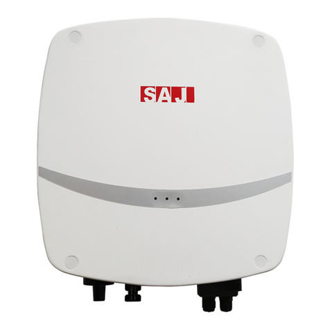
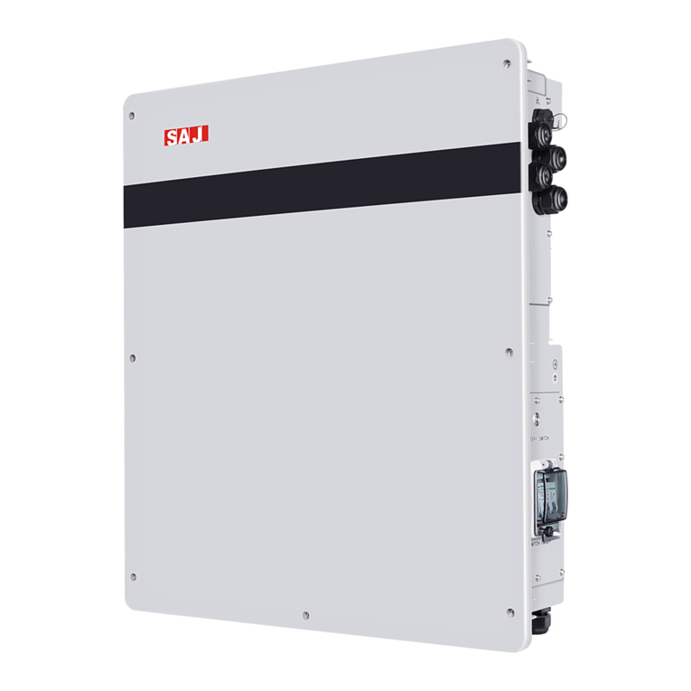
SAJ H1 Series User manual

H1 Series
- 0 -

H1 Series
- 1 -
Content
Chapter 1 Safety Precautions........................................................... - 3 -
1.1 Scope of Application............................................................................ - 3 -
1.2 Safety Instructions ............................................................................... - 3 -
1.3 Target Group......................................................................................... - 4 -
Chapter 2 Preparation........................................................................ - 4 -
2.1 Intended Use......................................................................................... - 4 -
2.2 Safety Instructions ............................................................................... - 4 -
2.3 Explanations of Symbols .................................................................... - 6 -
Chapter 3 Product Information.......................................................... - 7 -
3.1 Application Scope of Products........................................................... - 7 -
3.2 Overview and Dimensions of Products ............................................ - 7 -
3.3 Datasheet .............................................................................................. - 8 -
Chapter 4 Instructions for Installation ............................................ - 14 -
4.1 Safety Instructions ............................................................................. - 14 -
4.2 Pre-installation Check ....................................................................... - 14 -
4.3 The Determination of the Installation Method and Position........ - 15 -
4.4 Mounting Procedure .......................................................................... - 16 -
Chapter 5 Electrical Connection..................................................... - 19 -
5.1 Safety Instruction for Hot-line Job................................................... - 19 -
5.2 Specifications for Electrical Interface.............................................. - 20 -
5.3 AC Grid Wire and Backup Output Connection.............................. - 21 -
5.4 PV Connection.................................................................................... - 23 -
5.5 Battery Connection............................................................................ - 26 -
5.6 Earth Fault Alarm ............................................................................... - 28 -
5.7 Communication Connection............................................................. - 29 -
H1 Series
- 2 -
5.8 Connection Diagram.......................................................................... - 34 -
5.9 Ground Connection............................................................................ - 35 -
5.10 External AC Circuit Breaker and Residual Current Device ...... - 35 -
Chapter 6 Debugging Instructions.................................................. - 36 -
6.1 Introduction of Human-computer Interface.................................... - 36 -
6.2 First Run Setup................................................................................... - 37 -
6.3 Shut Down Inverter............................................................................ - 59 -
6.4 Monitoring Operation and Battery manage system...................... - 59 -
Chapter 7 Fault Code and Troubleshooting.................................. - 60 -
Chapter 8 Recycling and Disposal................................................. - 63 -
Chapter 9 Contact SAJ .................................................................... - 64 -
Warranty Card................................................................................... - 65 -

H1 Series
- 3 -
Chapter 1 Safety Precautions
1.1 Scope of Application
This User Manual describes instructions and detailed procedures for
installing, operating, maintaining, and troubleshooting of the following SAJ
hybrid solar inverters:
H1-3K-S2, H1-3.6K-S2, H1-4K-S2, H1-4.6K-LS2, H1-4.6K-S2, H1-5K-S2,
H1-5K-LS2, H1-6K-LS2, H1-6K-S2
Please read the user manual carefully before any installation, operation and
maintenance and follow the instruction during installation and operation.
Please keep this manual all time available in case of emergency.
1.2 Safety Instructions
DANGER
·DANGER indicates a hazardous situation, which, if not avoided, will result in death
or serious injury.
WARNING
·WARNING indicates a hazardous situation, which, if not avoided, can result in
death or serious injury or moderate injury.
CAUTION
·CAUTION indicates a hazardous condition, which, if not avoided, can result in
minor or moderate injury.
NOTICE
·NOTICE indicates a situation that can result in potential damage, if not avoided.

H1 Series
- 4 -
1.3 Target Group
Only qualified electricians who have read and fully understood all safety
regulations contained in this manual can install, maintain and repair the
inverter. Operators must be aware of the high-voltage device.
Chapter 2 Preparation
2.1 Intended Use
The product is not suitable for supplying power to life-support medical
equipment.
Loads connected to the product must have a CE identification label.
The maximum DC input voltage of the product must not be exceeded. Turn
off DC switch before any installation and operation.
2.2 Safety Instructions
DANGER
·There is possibility of dying due to electrical shock and high voltage.
·Do not touch the operating component of the inverter; it might result in burning or
death.
·To prevent risk of electric shock during installation and maintenance, please make
sure that all AC and DC terminals are plugged out.
·Do not touch the surface of the inverter while the housing is wet, otherwise, it
might cause electrical shock.
·Do not stay close to the inverter while there are severe weather conditions
including storm, lighting, etc.
·Before opening the housing, the SAJ inverter must be disconnected from the grid
and PV generator; you must wait for at least five minutes to let the energy storage
capacitors completely discharged after disconnecting from power source.

H1 Series
- 5 -
WARNING
·The installation, service, recycling and disposal of the inverters must be performed
by qualified personnel only in compliance with national and local standards and
regulations.
·Any unauthorized actions including modification of product functionality of any form
may cause lethal hazard to the operator, third parties, the units or their property.
SAJ is not responsible for the loss and these warranty claims.
·The SAJ inverter must only be operated with PV generator. Do not connect any
other source of energy to the SAJ inverter.
·Be sure that the PV generator and inverter are well grounded in order to protect
properties and persons.
CAUTION
·The inverter will become hot during operation. Please do not touch the heat sink or
peripheral surface during or shortly after operation.
·Risk of damage due to improper modifications.
NOTICE
·Public utility only.
·The inverter is designed to feed AC power directly to the public utility power grid; do
not connect AC output of the inverter to any private AC equipment.

H1 Series
- 6 -
2.3 Explanations of Symbols
Symbol
Description
Dangerous electrical voltage
This device is directly connected to public grid, thus all work to the
inverter shall only be carried out by qualified personnel.
Danger to life due to high electrical voltage!
There might be residual currents in inverter because of large capacitors.
Wait 5 MINUTES before you remove the front lid.
Notice, danger!
This is directly connected with electricity generators and public grid.
Danger of hot surface
The components inside the inverter will release a lot of heat during
operation. Do not touch metal plate housing during operating.
An error has occurred
Please go to Chapter 9 “Troubleshooting” to remedy the error.
This device SHALL NOT be disposed of in residential waste
Please go to Chapter 8 “Recycling and Disposal” for proper treatments.
Without Transformer
This inverter does not use transformer for the isolation function.
CE Mark
With CE mark & the inverter fulfills the basic requirements of the
Guideline Governing Low-Voltage and Electro-magnetic Compatibility.
RCM Mark
Equipment meets safety and other requirements as required by electrical
safety laws/regulations in Australian and New Zealand.
No unauthorized perforations or modifications
Any unauthorized perforations or modifications are strictly forbidden, if
any defect or damage (device/person) occurred, SAJ shall not take any
responsibility for it.

H1 Series
- 7 -
Chapter 3 Product Information
3.1 Application Scope of Products
H1 series products are hybrid solar inverters without transformers, and the
inverters are important components of energy storage systems.
The H1 inverters converts the DC generated by solar panels into AC which
is in accordance with the requirements of public grid and send the AC into
the grid, reduce the load pressure of the grid.
When the grid failure, provide AC source to supply important loads, achieve
uninterrupted power supply function.
3.2 Overview and Dimensions of Products
The dimensions of H1 series products are shown in Figure 3.1.
Figure 3.1 Dimensions of H1 series Product

H1 Series
- 8 -
3.3 Datasheet
MODEL
H1-3K-S2
H1-3.6K-S2
H1-4K-S2
H1-4.6K-LS
2
H1-4.6K-S2
Input(DC)
Max.PV Array
Power[Wp]@STC
4500
5400
6000
6900
6900
Max. DC Voltage [V]
600
MPPT Voltage Range
[V]
90~550
Nominal DC Voltage[V]
360
Start Voltage [V]
120
Min. DC Voltage [V]
80
Max. DC Input
Current[A]
12.5 / 12.5
Max. DC Short Circuit
Current[A]
15 / 15
Number of MPPT
2
DC Switch
Integrated
Battery Data
Battery Type
Lithium battery
Battery Input Voltage
/Range of Voltage [V]
48 / 42~58.4
Max./Rated Charge
Current [A]
60/60
100 / 100
Charging Mode Control
3-stages
Grid Data [On grid Mode]
Rated Output Power[W]
3000
3680
4000
4600
4600
Max. Output Power [VA]
3000
3680
4000
4600
4600
Rated Output Current
[A]
13.1
16.0
17.4
20.0
20.0
Max. Output Current [A]
13.6
16.7
18.2
20.9
20.9
Rated Grid voltage
/Range [V]
220V, 230V, 240V / 180V~280V
Rated Grid Frequency /
Range [Hz]
50 / 60 ±5
Power Factor [cos φ]
0.8 leading~0.8 lagging
Total Harmonic
Distortion [THDi]
<3%
Feed-in
L+N+PE
AC Output Data [Back-up Mode]

H1 Series
- 9 -
Max. Output Power [VA]
3000
4600
Output Voltage [V]
220/230/240
Output Frequency [Hz]
50/60
Total Harmonic
Distortion of Voltage
<3%
Peak Output Apparent
Power [VA]
3600, 10sec
5500, 10sec
Efficiency
Max. Efficiency
97.6%
Euro Efficiency
97.0%
Max. Battery to Load
Efficiency
94.6%
Protection
AC Short Circuit
Protection
Integrated
Overload Protection
Integrated
DC Overvoltage/
Undervoltage
Protection
Integrated
AC Overvoltage/
Undervoltage
Protection
Integrated
AC Overfrequency/
Underfrequency
High/Low Protection
Integrated
Over Thermal
Protection
Integrated
Anti-islanding
protection
Integrated
Peak-to-trough Period
Setting
Integrated
Interface
PV Connection Type
MC4
Battery Connection
Type
Terminal Block
AC Connection Type
Terminal Block
Display
LCD
Communication port
RS485*2& RS232&DRM*2(Integrated)
Communication Mode
Wi-Fi/GPRS/Ethernet(Optional)
General Data
Topology
Transformerless
Ingress Protection
IP65
Operating Temperature
-25~+60℃[45~60℃with derating]

H1 Series
- 10 -
Range
Ambient Humidity
0~100% No Condensing
Altitude
4000m(>3000m power derating)
Noise[dBA]
<29
Cooling method
Natural Convection
Dimensions[H*W*D][m
m]
470*470*190
Weight[kg]
23
Standard
Warranty[year]
5
Applicable Standard
IEC62109-1/2,IEC61000-6-1/2/3/4,EN50438,EN50549,C10/C11,IEC
62116,IEC61727,RD1699,UNE 206006,UNE 206007,CEI
0-21,AS4777.2,
CQC NB/T 32004,VDE-AR-N 4105

H1 Series
- 11 -
MODEL
H1-5K-LS
2
H1-5K-S2
H1-6K-LS
2
H1-6K-S2
Input(DC)
Max.PV Array
Power[Wp]@STC
7500
9000
Max. DC Voltage [V]
600
MPPT Voltage Range
[V]
90~550
Nominal DC Voltage[V]
360
Start Voltage [V]
120
Min. DC Voltage [V]
80
Max. DC Input
Current[A]
12.5 / 12.5
Max. DC Short Circuit
Current[A]
15 / 15
Number of MPPT
2
DC Switch
Integrated
Battery Data
Battery Type
Lithium battery
Battery Input Voltage
/Range of Voltage [V]
48 / 42~58.4
Max./Rated Charge
Current [A]
60/60
100 / 100
60/60
100 / 100
Charging Mode Control
3-stages
Grid Data [On grid Mode]
Rated Output
Power[W]
5000*1
6000
Max. Output Power
[VA]
5000
6000
Rated Output Current
[A]
21.8*2
26.1
Max. Output Current
[A]
22.7
27.3
Rated Grid voltage
/Range [V]
220V, 230V, 240V / 180V~280V
Rated Grid Frequency /
Range [Hz]
50 / 60 ±5
Power Factor [cos φ]
0.8 leading~0.8 lagging
Total Harmonic
Distortion [THDi]
<3%

H1 Series
- 12 -
Feed-in
L+N+PE
AC Output Data [Back-up Mode]
Max. Output Power
[VA]
3000
5000
3000
5000
Output Voltage [V]
220/230/240
Output Frequency [Hz]
50/60
Total Harmonic
Distortion of Voltage
<3%
Peak Output Apparent
Power [VA]
3600,
10sec
6000,
10sec
3600,
10sec
6000,
10sec
Efficiency
Max. Efficiency
97.6%
Euro Efficiency
97.0%
Max. Battery to Load
Efficiency
94.6%
Protection
AC Short Circuit
Protection
Integrated
Overload Protection
Integrated
DC Overvoltage/
Undervoltage
Protection
Integrated
AC Overvoltage/
Undervoltage
Protection
Integrated
AC Overfrequency/
Underfrequency
High/Low Protection
Integrated
Over Thermal
Protection
Integrated
Anti-islanding
protection
Integrated
Peak-to-trough Period
Setting
Integrated
Interface
PV Connection Type
MC4
Battery Connection
Type
Terminal Block
AC Connection Type
Terminal Block
Display
LCD
Communication port
RS485*2& RS232&DRM*2(Integrated)
Communication Mode
Wi-Fi/GPRS/Ethernet(Optional)
General Data
Topology
Transformerless

H1 Series
- 13 -
Ingress Protection
IP65
Operating Temperature
Range
-25~+60℃[45~60℃with derating]
Ambient Humidity
0~100% No Condensing
Altitude
4000m(>3000m power derating)
Noise[dBA]
<29
Cooling method
Natural Convection
Dimensions[H*W*D][m
m]
470*470*190
Weight[kg]
23
Standard
Warranty[year]
5
Applicable Standard
IEC62109-1/2,IEC61000-6-1/2/3/4,EN50438,EN5054
9,C10/C11,IEC62116,IEC61727,RD1699,UNE
206006,UNE 206007,CEI 0-21,AS4777.2,
CQC NB/T 32004,VDE-AR-N 4105
Note: *1 For AS/NZS 4777.2 Rated Output Power is 4999VA.
*2 For AS/NZS 4777.2 Rated Output Current is 21.7A.

H1 Series
- 14 -
Chapter 4 Instructions for Installation
4.1 Safety Instructions
DANGER
·Dangerous to life due to potential fire or electricity shock.
·Do not install the inverter near any inflammable or explosive items.
·This inverter will be directly connected with HIGH VOLTAGE power generation
device; the installation must be performed by qualified personnel only in compliance
with national and local standards and regulations.
NOTICE
·This equipment meets the pollution degree II.
·Inappropriate or the harmonized installation environment may jeopardize the life
span of the inverter.
·Installation directly exposed under intensive sunlight is not recommended.
·The installation site must be well ventilated.
4.2 Pre-installation Check
4.2.1 Check the Package
Although SAJ’s inverters have surpassed stringent testing and are checked
before they leave the factory, it is uncertain that the inverters may suffer
damages during transportation. Please check the package for any obvious
signs of damage, and if such evidence is present, do not open the package
and contact your dealer as soon as possible
4.2.2 Check the Assembly Parts
Please refer to the Packing List inside the package container.

H1 Series
- 15 -
4.3 The Determination of the Installation Method and
Position
4.3.1 Mounting Method
The equipment employs natural convection cooling, and it can be installed
indoor or outdoor.
Do not expose the inverter to direct solar irradiation as this could cause
power derating due to overheating.
Figure 4.1 Mounting Method
(2) Mount vertically or tilted backwards by max. 15°. Never install the
inverter tilted forwards, sideways, horizontally or upside down.
(3) Install the inverter at eye level for convenience when checking the LCD
display and possible maintenance activities.
(4) When mounting the inverter, please consider the solidness of wall for
inverter, including accessories. Please ensure the Rear Panel mount tightly.
To make sure the installation spot is suitably ventilated, if multiple SAJ hybrid
solar inverters are installed same area.

H1 Series
- 16 -
50CM
30CM
50CM
30CM
30CM
Figure 4.2 Minimum Clearance
4.4 Mounting Procedure
4.4.1 Mark the Positions of the Drill Holes of the Rear Panel
The mounting position should be marked as shown in Figure 4.3.
Figure 4.3 Dimensions of rear panel of H1 inverter

H1 Series
- 17 -
4.4.2 Drill Holes and Place the Expansion Tubes
Following the given guides, drill 4 holes in the wall (in conformity with
position marked in Figure 4.4, and then place expansion tubes in the holes
using a rubber mallet.
Figure 4.4 Drill holes dimensions of H1 inverter
4.4.3 Mount the Screws and the Rear Panel
The panels should be mounted in the mounting position by screws as shown
in Figure 4.5.
Figure 4.5 Mount the Rear Panel of H1 inverter

H1 Series
- 18 -
4.4.4 Mount the Inverter
Carefully mount the inverter to the rear panel as shown in Figure 4.6.
Make sure that the rear part of the equipment is closely mounted to the
rear panel.
Figure 4.6 Mount H1 inverter

H1 Series
- 19 -
Chapter 5 Electrical Connection
5.1 Safety Instruction for Hot-line Job
Electrical connection must only be operated on by professional technicians.
Please keep in mind that the inverter is a bi-power supply equipment. Before
connection, necessary protective equipment must be employed by
technicians including insulating gloves, insulating shoes and safety helmet.
DANGER
·Dangerous to life due to potential fire or electricity shock.
·When power-on, the equipment should in conformity with national rules and
regulations.
·The direct connection between the inverter and high voltage power systems must
be operated by qualified technicians in accordance with local and national power
grid standards and regulations.
WARNING
· When the photovoltaic array is exposed to light, it supplies a DC voltage to the
inverter.
NOTICE
·Electrical connection should in conformity with proper stipulations, such as
stipulations for cross-sectional area of conductors, fuse and ground protection.
·The overvoltage category on DC input port is II,on AC output port is III.
This manual suits for next models
9
Table of contents
Other SAJ Inverter manuals

SAJ
SAJ R6 Series User manual

SAJ
SAJ R6 S2 Series User manual

SAJ
SAJ R6 Series User manual

SAJ
SAJ 8000B series User manual

SAJ
SAJ eSolar RS485 User manual

SAJ
SAJ Suntrio Plus Series User manual

SAJ
SAJ S350 Series User manual

SAJ
SAJ R5 Series User manual

SAJ
SAJ R6 Series User manual

SAJ
SAJ H2 Series User manual

SAJ
SAJ Suntrio-TL Series User manual

SAJ
SAJ 8000m-2SR4GH User manual

SAJ
SAJ R5-3K-T2-15 User manual

SAJ
SAJ H2 Series User manual

SAJ
SAJ Suntrio Plus Series User manual

SAJ
SAJ R6 Series User manual

SAJ
SAJ Sununo-TL Series User manual

SAJ
SAJ H2 Series User manual

SAJ
SAJ AS1-3KS-5.1 User manual

SAJ
SAJ R6 Series User manual