SALSBURY INDUSTRIES
18300 Central Avenue, Carson, CA 90746-4008
Phone: 1-800-624-5269 Int’l Phone: 323-846-6700
Fax: 1-800-624-5299 Int’l Fax: 323-846-6800
www.mailboxes.com engineering@mailboxes.com
Installation instructions are provided as general guidelines. Itis advised that a professional installer be consulted. Salsbury Industries assumes no product assembly or installation liability.
Copyright © 2020 Salsbury Industries. All rights reserved. 11/1/11
Designer Roadside Mailboxes – 4325D
Deluxe Newspaper Holders on Deluxe Mailbox Post
Installation Instructions U.S.P.S. APPROVED
Installing Newspaper Holders on Deluxe Mailbox
Posts
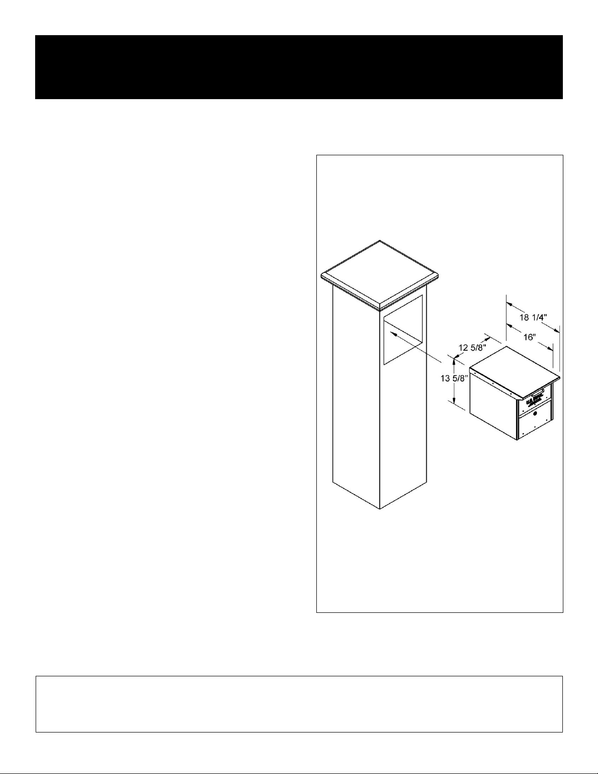
Thank you for selecting Salsbury’s 4325D designer roadside mailbox.
This instruction sheet is for installing the 4325D mailbox along with a 4315
newspaper holder on a deluxe mailbox post. Other installation instructions
are available for installing the mailbox on a pedestal, or on a deluxe mailbox
post, installing the mailbox on spreaders, and installing the pedestal in a
concrete footing.
When you install a curbside or roadside mailbox, make sure that it is easily
accessible to the mail carrier. By regulation a locked mailbox should be 41”
to 45” from the ground or street surface up to the point of mail entry. The
door should be set back 6” to 8” back from the front face of the curb or the
road edge. However, you should check with your local postmaster to ensure
that the mailbox is installed according to local regulations. It is important to
note that it is not the responsibility of mail carriers to open mailboxes that are
locked, accept keys for this purpose, or lock mailboxes after delivery of the
mail.
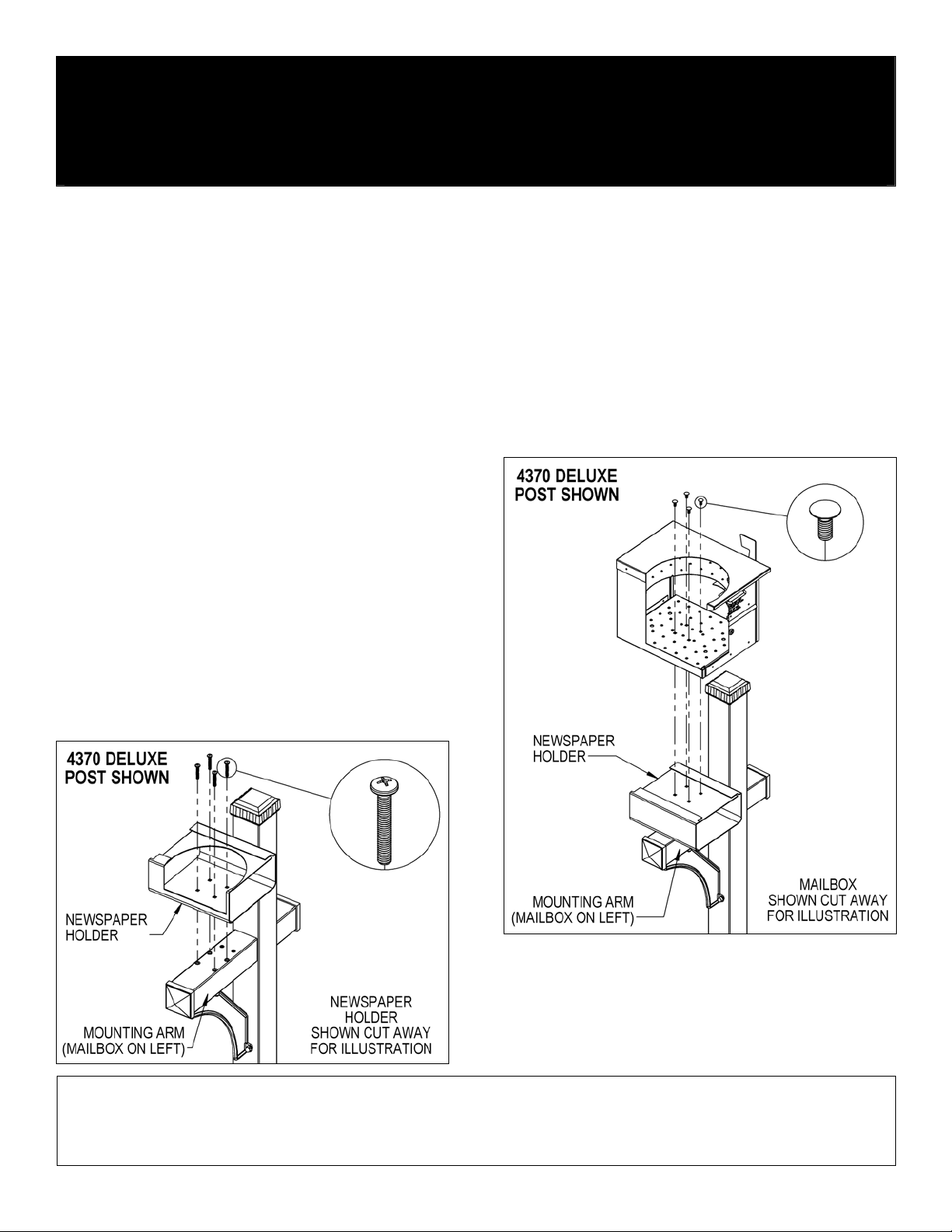
Newspaper Holder Installation to Deluxe Post
Installation of newspaper holders to each deluxe post, 4870 one-sided, or
4872, is the same. Attach one newspaper holder to the 4870 one-sided
post. Attach one additional newspaper holder to the 4872 two-sided post.
All hardware required to assemble the newspaper holders(s) to the deluxe
mailbox post is provided with the post. To attach a newspaper holder to the
post, install four (4) 5/16”-18 x 2” long pan head bolts through the four (4)
square holes shown in the inside floor of the newspaper holder and through
the four (4) tapped holes in the arm of the deluxe mailbox post. Repeat
these steps for the other newspaper holder(s).
Mailbox Installation to Newspaper Holders
Installation of the mailbox to the newspaper holder on each deluxe post,
4870 one-sided, or 4872 two-sided, is the same. Attach one mailbox to the
4870 one-sided post. Attach one additional mailbox to the 4872 two-sided
post. All hardware to attach the mailbox(es) to the newspaper holder(s) is
included with the newspaper holder(s). To attach a mailbox to a newspaper
holder, open the front door or rear door of the mailbox and install four (4)
5/16”-18 X 3/4” long carriage bolts into (4) square holes in the floor of the
mailbox and through the four (4) square holes shown on the top of the
newspaper holder. Install 5/16” flat washers and 5/16”-18 hex nuts on the
ends of the four (4) bolts protruding below the top of the newspaper holder.
Cover the hex nuts with cap plugs. Repeat these steps for the other
mailbox(es). Installation is now complete. Additional hardware provided is
not needed and may be discarded.
Note: On the 4370 deluxe mailbox post, the longer mounting arm which
accommodates the newspaper holder and mailbox can be on either the left
or right side. When attaching the post to the ground, position the post so the
longer mounting arm is on the side desired. Then mount the newspaper
holder and mailbox on the mounting arm with the mailbox facing the street or
roadway.