Salton SOD 12 Installation guide

INSTRUCTIONS AND WARRANTY
MODEL NO: SOD 12

2
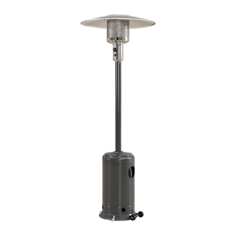
SALTON GAS PATIO HEATER

3
1. IMPORTANT SAFEGUARDS
CAUTION
PLEASE READ CAREFULLY THE FOLLOWING SAFETY GUIDELINES BEFORE
OPERATIONING THIS APPLIANCE.
Do not use the patio heater for indoors, as it may cause personal injury or
property damage.
This outdoor heater is not intended to be installed onto recreational vehicles
and/or boats.
Installation and repair should be done by a qualified service person.
Improper installation, adjustment, alteration can cause personal injury or
property damage.
Do not attempt to alter the unit in any manner.
Never replace or substitute the regulator with any regulator other than the
factory-suggested replacement.
Do not store or use petrol or other flammable vapors or liquids in the heater
unit.
The whole gas system, hose, regulator, pilot or burner should be inspected for
leaks or damage before use, and at least annually by a qualified service person.
All leak tests should be done with a soap solution. Never use an open flame to
check for leaks.
Do not use the heater until all connections have been leak tested.
Turn off the gas valve immediately if smell of gas is detected.
Do not transport heater while it is in operation.
Do not move the heater, after it has been turned off, until the temperature has
cooled down.
Keep the ventilation opening of the cylinder enclosure free and clear of debris.
Do not paint the radiant screen, control panel or top canopy reflector.
Control compartment, burner and circulation air passageways of the heater
must be kept clean.
Frequent cleaning may be required as necessary.
The LPG cylinder should be turned off when the heater is not in use.
Check the heater immediately if any of the following occurs:
-The heater does not reach its set temperature.
-The burner makes a popping noise during use (a slight noise is normal
when the burner is extinguished).
-The smell of gas in conjunction with extreme yellow tipping of the burner
flames.
The LPG regulator/hose assembly must be located out of pathways where people
may trip over it or in an area where the hose will not be subject to accidental
damage.
Any guard or other protective device removed for servicing the heater must be
replaced before operating the heater.
Adults and children should stay away from high temperature surfaces to avoid
burns or clothing ignition.
Children should be carefully supervised when they are in the area of the heater.
Clothing or other flammable materials should not be hung on the heater or
placed on or near the heater.

4
Important…Flash Back (i.e. Fire in the Burner Jet)
In the event of a flash back occurring in the burner tube (that is when the flame
burns inside the jet instead of the outside):
Immediately turn off the gas supply at the gas cylinder.
Turn the patio heater itself off at the control switches.
Disconnect the regulator and wait for the heater to cool down (about 5-10 min).
Once cooled, check the burner jet for blockages and follow cleaning instructions
as described under “Cleaning and Care” section.
If, upon relighting, the problem reoccurs, have your unit checked by an
authorized service dealer
2. HEATER STAND AND LOCATION
The heater is primarily for outdoor use only. Always ensure that adequate fresh
air ventilation is provided.
Always maintain proper clearance to combustible materials, i.e. top 450mm and
sides, 600mm minimum.
Heater must be placed on level firm ground.
Never operate heater in an explosive atmosphere like in areas where petrol or
other flammable liquids or vapors are stored.
To protect heater from strong wind, anchor the base securely to the ground with
screws.
Fortification of base to the ground
450 mm
600 mm

5
3. GAS REQUIREMENTS
Use LPG gas only.
The pressure regulator and hose assembly to be used must conform to local
standard codes.
The installation must conform to local codes, or in the absence of local codes,
with the standard for the storage and handling of liquid petroleum gases.
A dented, rusted or damaged LPG cylinder may be hazardous and should be
checked by your cylinder supplier. Never use an LPG cylinder with a damaged
valve connection.
The propane tank must be arranged to provide for vapor withdrawal from the
operating cylinder.
Never connect an unregulated LPG cylinder to the heater.
4. LEAKAGE TEST
Gas connections on the heater are leak tested at the factory prior to shipment. A
complete gas tightness check must be performed at the installation site due to possible
mishandling in shipment or excessive pressure being applied to the heater.
Make a soap solution of one part liquid detergent and one part water. The soap
solution can be applied with a spray bottle, brush or rag. Soap bubbles will
appear in case of a leak.
The heater must be checked with a full cylinder.
Make sure the safety control valve is in the OFF position.
Turn the gas supply ON.
In case of a leak, turn off the gas supply. Tighten any leaking fittings, then turn
the gas supply on and recheck.
Never leak test while smoking or near an open flame.
5. OPERATIONS AND STORAGE
5.1 TO TURN ON THE HEATER
1. Turn the valve on the gas supply cylinder completely “ON”.
2. Press and turn the Variable Control Knob to the PILOT position -
i.e. counter-clockwise 90.
3. Press down the Variable Control Knob and hold for 30 seconds. While holding
down the Variable Control Knob, press the Igniter button several times until the
pilot flame lights. Release variable control knob once the pilot flame is lit.

6
Note
If the new cylinder has just been connected, please allow at-least one minute
for the air in the gas pipeline to purge out through the pilot hole.
When lighting the pilot flame, ensure that the Variable Control Knob is
continuously pressed down while pressing the igniter button. The variable
Control Knob can be released once the Pilot Flame is alight.
The Pilot Flame can be check and viewed from the small round window with
the sliding lid, located at the bottom of the flame screen (to the left or right of
the controller).
If the Pilot Flame does not light or goes out, please repeat from Step 3.
4. After the Pilot Flame is lit, turn the Variable Control Knob to the minimum
position and leave there for 5 minutes before turning the knob to the desired
temperature position.
5.2 TO TURN OFF THE HEATER
1. Turn the Variable Control Knob to the Pilot position.
2. Press and turn the Variable Control Knob to the OFF position.
3. Turn the valve on the gas supply cylinder completely OFF.
5.3 STORAGE
Always close the gas valve of the gas cylinder after use or in the case of a
disturbance.
Remove the pressure controller and the hose.
Check the gas valve for both tightness and possible damage. If you suspect
damage, have it changed by your gas dealer.
Never store a liquid gas cylinder in a basement or in places where there is
inadequate ventilation.

7
6. CLEANING AND CARE
Wipe off powder coated surfaces with soft, moist rag. Do not clean heater with
cleaners that are combustible or corrosive.
Remove debris from the burner to keep it clean and safe for use.
Cover the burner unit with the supplied protective cover when the heater is not
in use.
7. PARTS AND SPECIFICATIONS

8
A. Construction and characteristics
Transportable terrace/garden heater with cylinder housing
Casing in steel with powder-coating or stainless steel
Gas hose connections with metal clamp (screw caps for Germany)
Stainless steel flame screen
Heat emission from reflector
B. Specifications
For outdoor use only
Uses LPG gas only
Max. Wattage: 12000 watts (41000 Btu)
Min. Wattage: 5000 watts (17000 Btu)
Consumption: 450g/hr max. 870g/hr
Weight: Metal w/ powder coating 20.5 kgs. (38.6 lbs.)
Stainless steel, 17.5 kgs. (38.6 lbs.)
Height: 224 cm including stand
With CE & CSA certificates
C. Table of openings
OPERATING PRESSURE
MAIN JET
PILOT JET
2.8 kP
1.9 mm
0.20 mm
8. ASSEMBLY PARTS
Tools needed:
Open end wrench 10 & 13 mm
Adjustable opening wrench (2) 20 cm long
Slip joint pliers 23 cm long
Philips screwdriver w/ medium blade
Spray bottle of soap solution for leakage test
Parts supplied:
Stand with LPG tank housing
Assembly post with 3 pcs post brackets
10 mm x 86 cm (L) galvanized steel pipe
Reflector 813 mm with 9 pcs Ø8 mm washers, 3 pcs M8 castle nut and 3 pcs M8
burner/reflector support bolt
4 pcs bolts M6 x 10 mm for assembly post and burner
6 pcs bolts & nuts M6 x 35 mm for post and post brackets
3 pcs bolts M8 x 16 mm for post brackets and stand
3 pcs ground fixer
6 pcs M6 x 10 mm ground fixer bolts & nuts

9
9. ASSEMBLY PROCEDURES
STEP 1
Put the 3 pcs post brackets on each position on the base as shown in the
picture.
Use 3 pcs M8 x 16 mm bolts to join the post brackets and stand.
STEP 2
Put the post on the top of 3 pcs post brackets.
Use 6 pcs M6 x 35 mm bolts and nuts to connect the post to the 3 pcs post
brackets. Tighten the bolts and nuts.
Square
Metal
Support
Stand
Bolt
Post
Nut
Bolt

10
STEP 3
Place the tank housing on the stand.
STEP 4
Fit the gas hose/pipe nut to the burner gas inlet connector.
Tighten the gas hose/pipe nut and gas inlet thread.
Fix the completed burner unit to the post by 4 pcs M6 x 10 mm bolts.
Tank Housing
Bolt

11
STEP 5
Check whether the connection of vertical post and burner are assembled
according to instructions, and all bolts and nuts are tightened.
Put washer Ø8 mm on each reflector support bolt.
STEP 6
Fasten the reflector with 3 pcs washers and 3 pcs M8 mm dome nuts.
Reflector Flat
Washer
Nut
Reflector
Nut
Reflector

12
STEP 7
Bring up the tank housing and rest it on the post plate.
Connect the regulator to the gas tank and tighten it with adjustable wrench.
Connect the end thread of inlet gas hose to the regulator.
Put LPG gas tank on the stand.
Gas
Cylinder
Regulator

13
10. MAINTENANCE AND SERVICING INSTRUCTIONS
There is very little maintenance required on this appliance. Important points to
remember are:
Always check that the regulator seal is undamaged when changing the gas
cylinder.
Always check that the hose is in good condition before using and that it is
securely clamped on to the appliance and the regulator.
It is recommended that the hose be replaced every two years whether it has
been used or not. When replacing the hose, make sure that it is with a hose
that complies with SABS 1156-2 or BS 3212. These are available mainly
from Hardware Stores and from the manufacturer and are orange in colour.
Remember when replacing the hose to replace the hose clamps at the same
time.
With the exception of the hose and the regulator, there are no user fitted
parts available for this heater. Should the heater not be functioning properly,
an authorized service agent must check it, and if replacement parts are
required, they will ensure that the correct parts are supplied and fitted
correctly.
It is recommended to have your heater checked at your local hardware store
at the beginning of every season.
WARNING
Wipe the exterior of the heater with a soft cloth moistened with a mild
detergent.
Do not use metal or furniture polish on the heater.
Only clean the heater when it is cold and not in use.
Do not use abrasive cleaners, which will damage the paint surface.
When not in use, store the heater by covering it and placing in a cool, dry
and dust free area.
If you need to return the appliance for a credit after consulting the supplier,
make sure that:
1. The unit is packed carefully back into its original packaging.
2. Proof of purchase is attached.

14
11. PROBLEMS CHECK LIST
PROBLEM
PROBABLE CAUSE
SOLUTION
Pilot Flame will not light
Gas valve may be OFF
Turn the valve ON
Tank fuel is empty
Refill the LPG tank
Opening is blocked
Clean or replace the opening
Air in supply system
Purge air from the lines
Loose connections
Check all fittings
Pilot Flame will not stay lit
Debris around the Pilot
Light
Clean the dirty area
Loose connections
Tighten the connections
Thermocouple is poor
Replace the thermocouple
Gas leak in the line
Check connections
Lack of fuel pressure
Cylinder nearly empty –refill
with LPG
Burner will not light
Pressure is low
Cylinder near empty –refill
with LPG
Opening blocked
Remove and clean
Control not ON
Turn valve ON
Thermocouple poor
Replace thermocouple
Pilot light assembly bent
Place pilot properly
Not in the correct location
Position properly and retry

15
PLEASE AFFIX YOUR PROOF OF PURCHASE/RECEIPT HERE
IN THE EVENT OF A CLAIM UNDER WARRANTY THIS RECEIPT MUST BE
PRODUCED.
W A R R A N T Y
1. Tedelex Trading (Pty) Limited (“Tedelex”) warrants to the original purchaser of this product
(“the customer”) that this product will be free of defects in quality and workmanship which
under normal personal, family or household use and purpose may manifest within a period of 1
(one) year from the date of purchase (“warranty period”).
2. Where the customer has purchased a product and it breaks, is defective or does not work
properly for the intended purpose, the customer must notify the supplier from whom the
customer bought the product (“the supplier”) thereof within the warranty period. Any claim in
terms of this warranty must be supported by a proof of purchase. If proof of purchase is not
available, then repair, and/or service charges may be payable by the customer to the supplier.
3. The faulty product must be taken to the supplier's service centre to exercise the warranty.
4. The supplier will refund, repair or exchange the product in terms of this warranty subject to
legislative requirements. This warranty shall be valid only where the customer has not broken
the product himself, or used the product for something that it is not supposed to be used for.
The warranty does not include and will not be construed to cover products damaged as a result
of disaster, misuse, tamper, abuse or any unauthorised modification or repair of the product.
5. This warranty will extend only to the product provided at the date of the purchase and not to
any expendables attached or installed by the customer.
6. If the customer requests that the supplier repairs the product and the product breaks or fails to
work properly within 3 (three) months of the repair and not as a result of misuse, tampering or
modification by or on behalf of the customer, then the supplier may replace the product or pay
a refund to the customer.
7. The customer may be responsible for certain costs where products returned are not in the
original packaging, or if the packaging is damaged. This will be deducted from any refund paid
to the customer.
TEDELEX TRADING (PTY) LTD (JOHANNESBURG)
JOHANNESBURG TEL NO. (011) 490-9000
CAPE TOWN TEL NO. (021) 552-5161
DURBAN TEL NO. (031) 792-6000
www.amap.co.za
Table of contents
Popular Patio Heater manuals by other brands

Blue Sky Outdoor Living
Blue Sky Outdoor Living PFP2416-C owner's manual

Calcana
Calcana PH Series Specifications, Installation, Operation Service and Spare Parts Manual

Universal Innovations
Universal Innovations Sahara X13 Assembly & user instructions

Lava Heat
Lava Heat Ember owner's manual

EAST OAK
EAST OAK SPH22001 owner's manual

CAMBRIDGE
CAMBRIDGE CUW012-BLK user manual