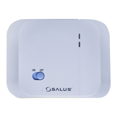
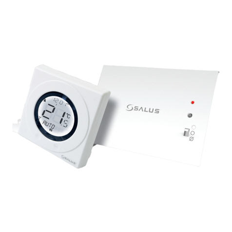
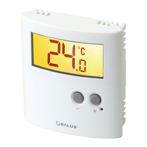
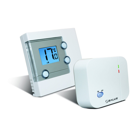
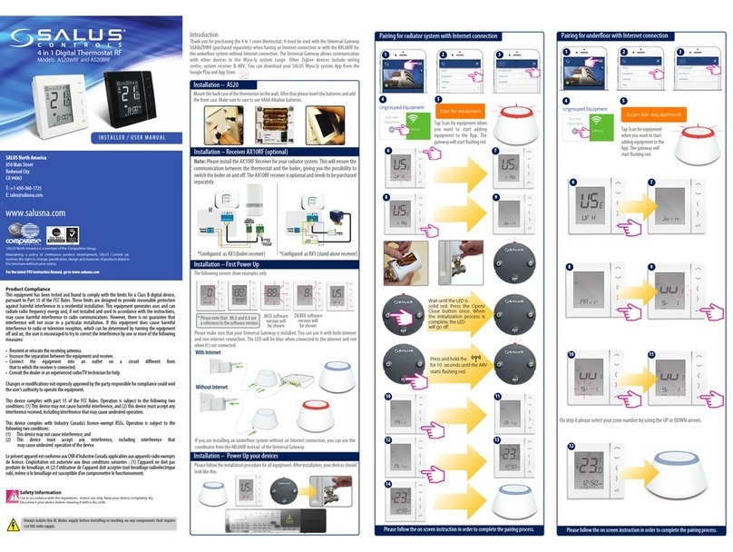
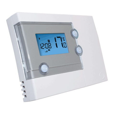
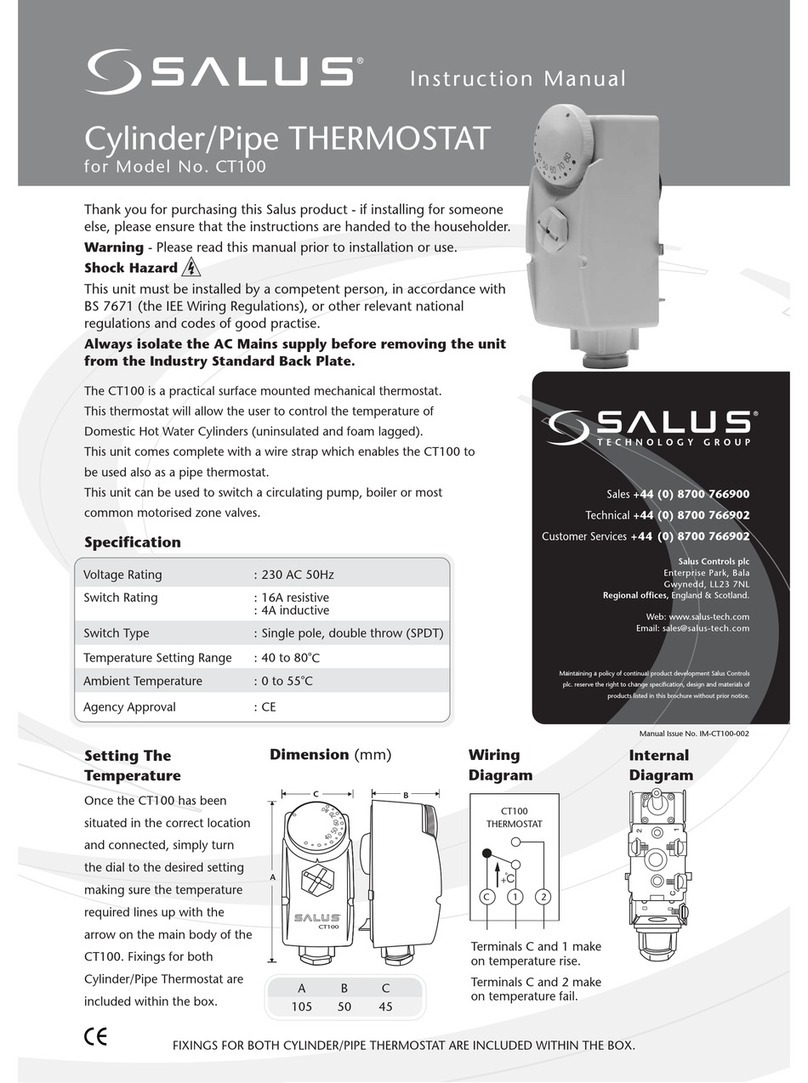
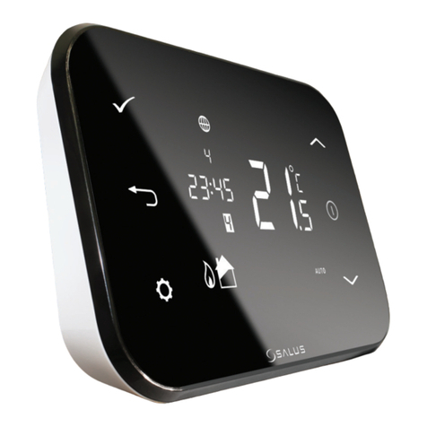
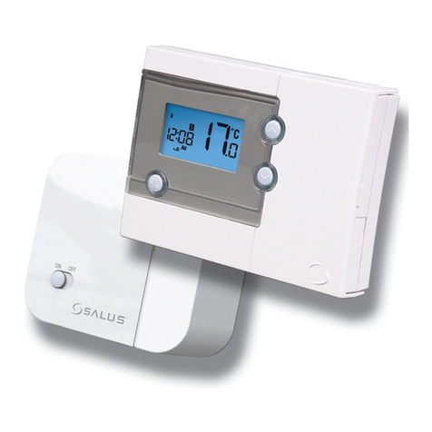
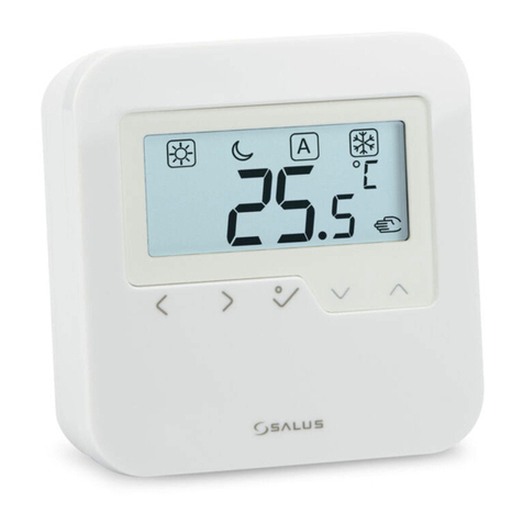
Salus VS20WRF User manual

1VS20WRF and VS20BRF Installer Manual
4 in 1 Digital Thermostat RF
Models: VS20WRF and VS20BRF
VS10WRF and VS10BRF
INSTALLER / USER MANUAL

2VS20WRF and VS20BRF Installer Manual
Contents
1 x Installer / User manual
4x AAA Batteries
VS20RF
Fixing screws
Contents
Box contents
Introduction
Product Compliance
System options overview
Installation
Parameter Settings
Error Codes
User Guide
Installers notes
Warranty
Box Contents
Icons used in this manual:
Safety
Important info
Your benefit
For latest PDF installation
guide please go to
www.salus-controls.com
VS10RF

3VS20WRF and VS20BRF Installer Manual
Product Compliance & Safety Information
INTRODUCTION
Thank you for purchasing the SALUS 4 in 1 room
thermostat. It must be used with the UG600/
UGE600 or with the CO10RF Zigbee Coordinator.
The Zigbee universal gateway/coordinator
allows communication with other devices in the
Salus SmartHome range. Other Zigbee devices
include wiring centre, system receiver & TRV.
Salus SmartHome Range
Safety Information
Use in accordance with the regulations. The
SALUS VS10RF/VS20RF is to be used for room
control of heating and hot water systems inside
the house.
SALUS Wiring Centre KL08RF
RX10RF
We hope you enjoy this product...
VS20 Thermostat
CO10RF
TRV10RFM
These instructions are applicable to the SALUS
model stated on the front cover of this manual
only.
Warning
This product must be fitted by a competent
person, and installation must comply with
the guidance, standards and regulations
applicable to the city, country or state where
the product is installed. Failure to comply with
the requirements of the relevant guidance,
standards and regulations could lead to injury,
death or prosecution.
UG600/UGE600

4VS20WRF and VS20BRF Installer Manual
Product Compliance & Safety Information
Installer parameter settings
The SALUS VS20 are equipped with installer parameter
section (see page 71) this must only be entered by
the installer or competent person. Changing these
parameters can have a serious effect on your heating
system
For the installer
Please enter any parameter changes in the installer
notes section (pages 111)
230V AC
Sources of danger
The thermostat must be disconnected from main
supply before removing the cover.
Emergency
Switch off the voltage to the individual thermostat
wring centre or complete system.
Warning
Always isolate the AC Main supply before
installing or working on any components that
require 230 VAC 50Hz supply.
This product complies with the essential requirements
and other relevant provisions of Directives 2014/30/
EU, 2014/53/EU (2014/35/EU forVS10WRF/VS10BRF)
and 2011/65/EU. The full text of the EU Declaration
of Conformity is available at the following internet
address: www.saluslegal.com.
Product Compliance

5VS20WRF and VS20BRF Installer Manual
System Overview - Configuration Options
Programmable Room
Thermostat (PRT)
* Grouping and timer option only available
when used with wiring centre.
1
UFH Manifold
Wiring Centre
Radiator
Boiler
Hot Water
TRV
Towel Rails
Group Control
Thermostat*
2
Group
Thermostat*
3
Timer
4
The unit can be configured to
either one of the following

6VS20WRF and VS20BRF Installer Manual
System Overview - Configuration Options
Programmable Room Thermostat (PRT)
When configured for PRT (see page 30) it mainly works by itself and allows the user to have separate Time
and Temperature control of each zone on the wiring centre, radiator valve or system receiver. Features
like Vacation , Party frost mode have to set on each individual thermostat. All PRTs paired with a wiring
centre can also use the global heat/cool changeover function if the your system supports this. This is
achieved by using the heat/cool changeover connection on the wiring centre (see wiring centre guide).
Group Control Thermostat
When configured for a PRT (see page 30) it can operate as a group control thermostat by assigning a
group when pairing with the wiring centre this allows central control of up to 7 group thermostats see
below, there can be a maximum of 2 groups per 8 zone wiring centre. Permanent temperature override,
Holiday, Party, Frost modes, can be selected centrally from the Group Control Thermostat. Holiday will
also be applied to a timer if applicable. The group thermostats can be also globally changed from heating
to cooling thermostats if you system supports this by using the switched input connection on the WC.
Group Thermostat
When configured as a digital thermostat and assigning a group when pairing with a WC it can operate as
a group thermostat (see page 29), in group mode the group thermostat will follow the time schedule and
any override modes of the group control thermostat. At least one group control thermostat is required for
grouping see above. The group thermostat can have its own programmed temperatures, manual override
and also be removed from the group temporarily or permanently.
Timer
When configured to timer the unit will operate as a timer with no temp control. This can be used for hot
water control. The timer will also follow Holiday mode from the group control thermostat if applicable.
SYSTEM
OVERVIEW
7VS20WRF and VS20BRF Installer Manual
System Overview - Zigbee Coordinator
Zigbee coordinator required for communication between these devices.
RX10RF
CO10RF TRV10RFM
KL08RF
VS20RF
UG600/UGE600

8VS20WRF and VS20BRF Installer Manual
System Overview - Salus SmartHome System
The thermostat can communicate with all these Salus SmartHome
devices.
System Receiver configured to boiler receiver.
Refer to system receiver manual RX10RF.
System Receiver
configured to one
room receiver RX2.
Refer to system
receiver RX10RF.
UNDERFLOOR HEATINGMANIFOLD
Max 6 TRV per thermostat
KL08RF or KL08NSB can be used
SYSTEM
OVERVIEW

9VS20WRF and VS20BRF Installer Manual
System Overview - Hot Water Option
Unit configured to
Hot Water Timer.
When the unit is configured as a hot water timer (see page 32)
there are two methods of connecting the cylinder thermostat.
Cylinder thermostat options
1Connected direct to WC (Default)
2Connected direct to VS20RF (requires additional parameter change. See page 71)

10 VS20WRF and VS20BRF Installer Manual
System Overview - Hot Water Option
1Connected direct to WC (Default)
For convenience there is a unique built in option allowing the cylinder
thermostat to be connected to either the HW Timer or Wiring Centre.
Please refer to Wiring Centre guide and pages 15, 20 for more information.
2Connected direct to VS20RF
(requires additional parameter change see page 32)
SYSTEM
OVERVIEW

11 VS20WRF and VS20BRF Installer Manual
Installation – Thermostat Mounting
Not to be positioned on an exterior wall.
For your benefit symbol
To ensure trouble free operation and efficient control. the room thermostat Nea
is best positioned behind a door and at 130cm from the floor.
(Pic)
Do not position the thermostat:
1. Near any heat source (pics)
2. Behind curtains(pic)
3. Direct Sunlight(pic)
4. In a bathroom or area of high humidity(pic)
Info symbol
· Not to be positioned on exterior wall
· Do not install the remote sensor (if applicable) in an empty tube
· Only the temperature at the position of remote sensor (if applicable) is measured
130cm
130cm
Mounting position and installation
To ensure trouble free operation and efficient control, the unit is best positioned
in a draft free area and at more than 1.5 m from the floor. Do not position the
thermostat near any heat source, behind curtains, direct sunlight or an area of
high humidity.
1.5 m

12 VS20WRF and VS20BRF Installer Manual
Carefully remove the front housing.
Installation – Thermostat Mounting VS20WRF
1 3
2
60mm
INSTALLATION

13 VS20WRF and VS20BRF Installer Manual
Installation – Terminal Connections VS20WRF
Understanding your terminal connections
Rear of unit
Sensor Terminals
Can be used for external AIR,
Floor sensor when configured
as thermostat. Can also be
used for Cylinder thermostat
when configured for HW.
See page 71.
1
1

14 VS20WRF and VS20BRF Installer Manual
Installation – Thermostat External Sensor VS20WRF
Note: If you are using an external sensor, the unit has to be configured for
External Air Sensor or Floor Protection Sensor please see device parameter
setting page 71.
SALUS External sensor (Sold separately)
INSTALLATION

15 VS20WRF and VS20BRF Installer Manual
Installation – Hot Water Timer Cylinder Thermostat VS20WRF
Note: The unit can be configured for Cylinder thermostat or connected to the
Hot Water Timer. Please see device parameters page 71. For additional Wiring
Centre information refer to note 1 on Wiring Centre guide.
HW Timer connected cylinder thermostatWC connected cylinder thermostat (Default)
ZONE1
SL N L SL N L SL N L SL N L SL N L SLN L SL N LSL N L
ZONE2ZONE3ZONE4ZONE5 ZONE6ZONE7 ZONE8
5x 20mm
5x 20mm
Link must be fitted
ZONE1
SL N L SL N L SL N L SL N L SL N L SLN L SL N LSL N L
ZONE2ZONE3ZONE4ZONE5 ZONE6ZONE7 ZONE8
5x 20mm
5x 20mm
Cylinder
thermostat
IN OUT
IN OUT

16 VS20WRF and VS20BRF Installer Manual
Installation – Thermostat Mounting VS20WRF
1 2
34
Once you have connected your choice of external sensor (if applicable)
Insert batteries
INSTALLATION

17 VS20WRF and VS20BRF Installer Manual
Carefully remove the front housing.
1 3
2
Installation – Thermostat Mounting VS10WRF
60mm
INSTALLATION

18 VS20WRF and VS20BRF Installer Manual
Installation – Terminal Connections VS10WRF
Understanding your terminal connections
Rear of unit Power Terminals 230 Vac
Used for supplying power
to the unit. 230V supply can
be sourced from the wiring
centre or any convenient
source.
Sensor Terminals
Can be used for external AIR,
Floor sensor when configured
as thermostat. Can also be
used for Cylinder thermostat
when configured for HW.
1
2
12

19 VS20WRF and VS20BRF Installer Manual
Installation – Thermostat External Sensor VS10WRF
Note: If you are using an external sensor, the unit has to be
configured for External Air Sensor or Floor Protection Sensor please
see device parameter setting page 71.
SALUS External sensor (Sold separately)
INSTALLATION

20 VS20WRF and VS20BRF Installer Manual
Installation – Hot Water Timer Cylinder Thermostat VS10WRF
Note: The unit can be configured for Cylinder thermostat or connected to
the Hot Water Timer. Please see device parameters page 71. For additional
Wiring Centre information refer to note 1 on Wiring Centre guide.
HW Timer connected cylinder thermostatWC connected cylinder thermostat (Default)
ZONE1
SL N L SL N L SL N L SLN L SL N L SL N L SL N LSL N L
ZONE2ZONE3ZONE 4ZONE5 ZONE6ZONE7 ZONE8
5x 20mm
5x 20mm
Link must be fitted
ZONE1
SL N L SL N L SL N L SLN L SL N L SL N L SL N LSL N L
ZONE2ZONE3ZONE 4ZONE5 ZONE6ZONE7 ZONE8
5x 20mm
5x 20mm
Cylinder
thermostat
SALUS CT100
IN OUT
IN OUT
Other manuals for VS20WRF
4
This manual suits for next models
3
Table of contents
Other Salus Thermostat manuals

Salus
Salus ST910WZ CA User manual

Salus
Salus RT300 User manual

Salus
Salus ST620VBC Owner's manual

Salus
Salus ST880ZB User manual

Salus
Salus 091FLRF User manual

Salus
Salus ST320RF User manual

Salus
Salus QUANTUM SQ610RF User manual

Salus
Salus RT 10 User manual

Salus
Salus HTR24 User guide

Salus
Salus EP110 User manual

Salus
Salus HTRS230 User guide

Salus
Salus RT305TX User manual

Salus
Salus ZigBee User manual

Salus
Salus 091FLRF User manual

Salus
Salus Optima S User manual

Salus
Salus Quantum SQ610 User manual

Salus
Salus RT500 User manual

Salus
Salus VS10WRF User manual

Salus
Salus FC600 User manual

Salus
Salus BTR230 User manual