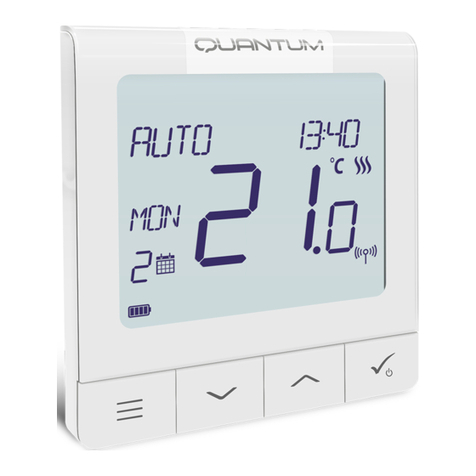
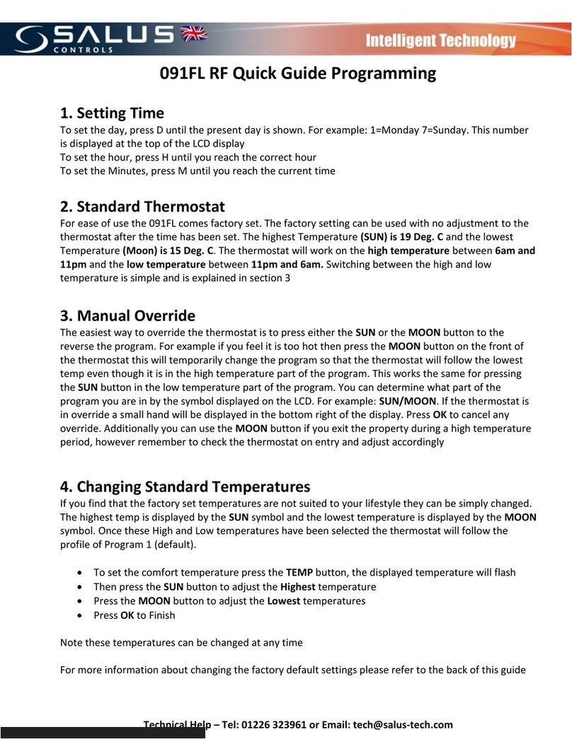
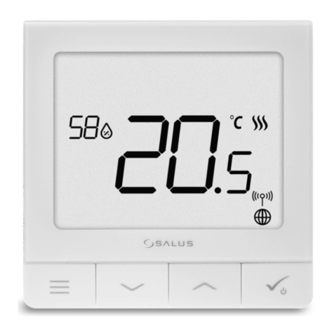
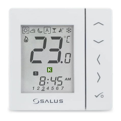
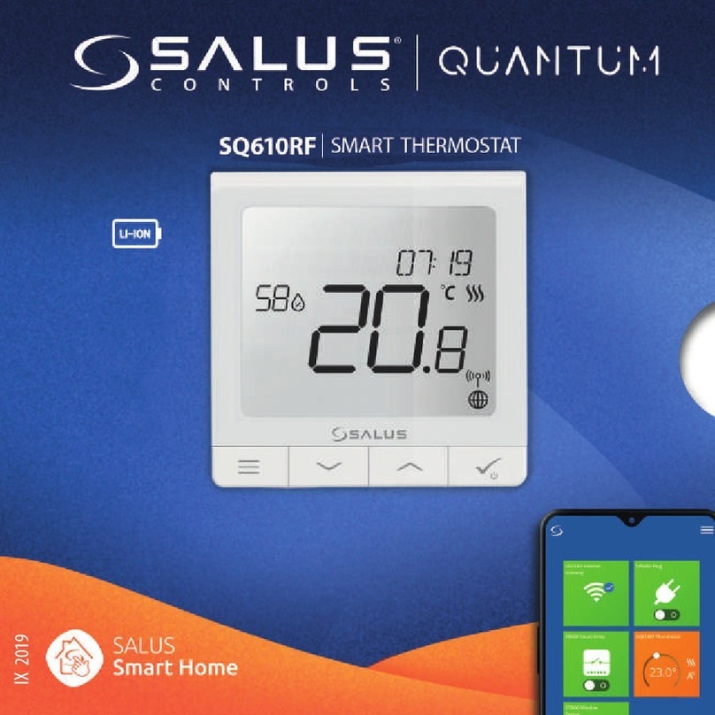
Salus QUANTUM SQ610RF User manual

IX 2019

2
Introduction
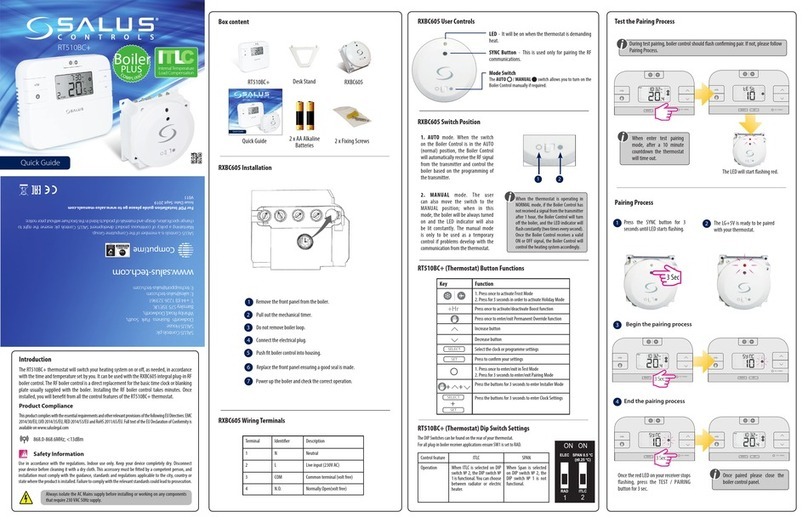
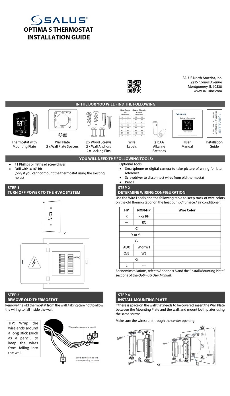
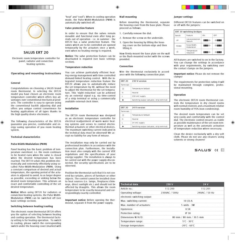
The SQ610RF Quantum is a ZigBee temperature controller for wireless control of iT600 series devices, such as
the KL08RF wiring centre, mini TRV head, RX10RF boiler control module.
In order to control SQ610RF over the Internet or via the SALUS Smart Home mobile app (ONLINE mode),
it must be installed together with the UGE600 Internet gateway (sold separately). From the application level,
it is possible to pair SQ610RF with other system elements, e.g. Smart Plug SPE600, Smart Relay SR600 or
window/door sensor OS600/SW600.
SQ610RF can be used locally without an Internet connection (OFFLINE mode), however, it’s communication
with other devices must be done using the CO10RF coordinator (sold separately).
Full manual in PDF format is available at www.salus-controls.eu site.
UseinaccordancetonationalandEUregulations.Usethedeviceasintended,keeping it in dry condition.Productfor
indoor use only. Installation must be carried out by a qualied person in accordance to national and EU regulations.
Disconnect your equipment before cleaning it with a dry cloth.
Product Compliance
Safety Information
This product complies with the essential requirements and other relevant provisions of Directives 2014/30/ EU,
2014/35/EU, 2014/53/EU and 2011/65/EU. The full text of the EU Declaration of Conformity is available at the
following internet address: www.saluslegal.com.
Package Content:
1) SQ610RF QuantumThermostat
2)Wall mounting plate
3) Self-adhesive mounting tape
4) Mounting screws
5) Manual instruction
3
Français Deutsch
Nederlands English
Before you start:
Charging to full battery level may take up to
24h maximum.
New SQ610RF Quantum Thermostat is partially
charged, however, we recommend you to fully
charge the battery before use.
Connect charger to micro-USB Port which is at
the bottom of SQ610RF Quantum Thermostat to
charge the device.
Wiring diagram (S1, S2 Input)
Symbols explanation:
S – volt-free contact
T – temperature sensor
S1,S2 Terminals:
- air or oor temperature sensor
- external volt-free contact to connect any
ON/OFF switch or occupancy sensor (Hotel card)
Mounting: to mount thermostat you can use
included accesories (mounting screws or
self-adhesive tape). Remove back cover
to mount the plate to the wall. After this just
attach thermostat to the plate (it has built-in
magnet).
Please note:
The ideal position to thermostat mounting is about
1,5m under oor level far from heating or cooling
sources. Thermostat can’t be exposed to sunlight
or any extreme conditions like for example draft.
1 2
3
S1
S2
T
S

4
1. Menu/Settings description + Clock
2. AM/PM
3. Temperature unit
4. Heating indicator (icon is animating when
there is heating demand)
5. Cooling indicator (icon is animating when
there is cooling demand)
6. RF Connection indicator
7. Internet connection indicator
8. Occupancy sensor (hotel card)
9. Key lock function
10. Standby mode icon
11. Current Temperature / Setpoint Temperature
12. Holiday mode
13. Temporary override mode
14. Settings icon
15. Baterry status indicator
16. External / Floor temp sensor indicator
17. Schedule program number
18. Schedule mode icon
19. Day indicator/ SET information
20. Current Humidity value
2
8
9
10111214
15
20
19
18
17
16
1
3
4
5
6
7
13
LCD Icon Description

5
Buttons DescriptionButtons Description
1) Menu button / Return button.
2) In the MAIN SCREEN: Press and hold for 3 sec to change the thermostat operating mode
(Schedule mode / Permanent mode /Temporary override mode).
3) In the SETTINGS SCREEN:
Press and hold for 3 sec to go back without saving the changes.
4) In the PAIRING SCREEN (in SYSTEM TYPE Menu): Press and hold for 3 sec to see other
pairing options.
+
In the MAIN SCREEN - press and hold these buttons together for 3 seconds to LOCK / UNLOCK
the Thermostat keys).
“Up”Button (Increase parameter value/moving on the menu in‘UP’direction)
„Down”Button (Decrease parameter value/moving on the menu in‘DOWN’direction)
1) Press and hold for 3 seconds to POWER UP new device
2)“OK /Tick”Button (Conrm parameter value / Go to the next menu / Save settings)
3) In the MAIN SCREEN: Press and hold for 3 seconds to enter Standby mode
4) In the SETTINGS SCREEN: Press and hold for 3 sec to go back to the MAIN SCREEN & SAVE all the changes.
5) During PAIRING process – hold button for 3 seconds to POWER OFF or REBOOT the thermostat.
Button Function
Français Deutsch
Nederlands English

6
COMPATIBILTY WITH OTHER SALUS CONTROLS DEVICES
QuantumThermostat can work in ONLINE or OFFLINE mode.QuantumThermostat can work in ONLINE or OFFLINE mode.
At rst step you need to decide in which mode your thermostat will work.At rst step you need to decide in which mode your thermostat will work.
ONLINE MODE OFFLINE MODE
Universal Gateway is
CONNECTED TO THE INTERNET
You can congure and use all your
devices in the Smart Home App
Download the Smart Home
App on your iOS or Android
device for remote access to your
SALUSequipment. SALUS
Smart Home
CO10RF Coordinator - You can use
standard ZigBee network coordinator
toinstallanduse yourdevices.
Universal Gateway is NOT
CONNECTED TO THE INTERNET
You can use your devices locally
without the SmartHome App.
Gateway works in this mode as
standard ZigBee coordinator.
OR
Compatibile devices:
KL08RF
Wiring Centre for 8-zone
underoor heating (UFH).
TRV
(Thermostatic
Radiator Valve) with
wireless communication.
RX10RF
receiver
SR600*
Smart Relay SPE600*
Smart Plug
*Only with Online Mode
GET IT ON
Download on the

7
First power up sequence
To power on the Thermostat hold
button for 3 seconds...
3 sec.
For easier installation, please make sure you have already added other devices to your ZigBee network, such as
Underoor Heating Control Box (KL08RF) or Radiator heads (TRV’s) etc.
Please note:
Now, choose your language by
„” or „ ” buttons. Conrm
your language by button.
...display will showall icons...
...then thermostat will display
the software version.
MENU / Press for 3 sec
to POWER UP
For more information
scan this code or visit:
www.salus-controls.com
3 sec
Removethe protection foil
3
2
5
1
4
Français Deutsch
Nederlands English

8
Installation in ONLINE mode
AfterLanguageselection followbelowstepstoadd your device to the SmartHome app andpair with other devices:
2
8
7
4
1
SALUS
SmartHome
Go to SALUS Smart Home app
3
Once your thermostat is added to
the app you will see above screen
on the LCD.
9
56

9
11 1210
13 14 15
Name this equipment
SQ610RF Thermostat
Connect equipment
Finish
3
After that thermostat will display
main screen.
Congratulations!You succesfully
congured SQ610RF Quantum
Thermostat.
Français Deutsch
Nederlands English

10
Installation in OFFLINE mode
Pairing with Wiring Centre / Control Box (Install the Wiring Centre / Control Box according to
the instructions included with product)
123
Open the ZigBee network
4
7
56
Select system type: UNDERFLOOR,
press button to conrm.
Using and buttons select theControl
Box number (press PAIR button on the Control
Box to see its address number). Press
button to conrm.
Use or buttons to select
the zone number and press
button to conrm.
8
Now you can pair your thermostat
with additional zones. Select one
more zone or nish the pairing process
by button.
OR
5 sec.
5 sec.
9
Close the ZigBee network
OR
3
3
5 sec.
5 sec.

11
7
54
3
6
Open the ZigBee network
Select system type:
RADIATORS
Now hold antenna button for 10
sec. on all TRV’s which you want
to pair with your Termostat.
Pairing with TRV radiator head (Install the TRV accordingto theinstructions includedwith
product)
On the LCD you will see the number of paired
TRV’s. Once all TRV’s are paired - press
button to nish the pairing process.
OR
5 sec.
5 sec.
10 sec
12
98
Close the ZigBee network
OR
5 sec.
5 sec.
You can pair up to 6 TRV’s with 1
Thermostat. All TRV’s have to within
the same room withThermostat.
3
3
Français Deutsch
Nederlands English

12
SQ610RF Full menu structure
Schedule settings
User settings
Admin settings
Language
TIME/DATE
HOLIDAY MODE
THERMOSTAT CALIBRATION
SHOW/HIDE DISPLAY HUMIDITY
SHOW/HIDE DISPLAY FLOOR
STANDBY TEMP SETPOINT
HEAT/COOL
RESET USER SETTINGS
TEMPERATURE SCALE
DISPLAYTEMPERATURE RESOLUTION
1.
HEAT CONTROL ALGORITHM 2.
COOL CONTROL ALGORITHM
S1/S2 INPUT 3.
MINIMUM SETPOINT
MAXIMUM SETPOINT
VALVE PROTECTION 4.
MINIMUM TURN OFF TIME 5.
OPTIMISATION FEATURE 6.
COMFORT WARM FLOOR 7.
PIN CODE
DEVICE INFORMATION 8.
FACTORY RESET 9.
ENGLISH
DANISH
POLISH
...
DISABLE
MO-FR+SA-SU
MO-SU
SINGLE DAYS
Main menu

13
Short description of some selected functions
(all functions are described in the full version of the SQ610RF manual):
1. DISPLAY TEMP RESOLUTION: This function determines the resolution of the displayed temperature -
User can temperature set by steps (every 0,5°C or 0,1°C).
2. CONTROL ALGORITHM: This function denes how to control the room temperature. Available options
are: ITLC for Underoor Heating / Radiators / Electrical Heating (that’s advanced algorithm for precise
maintenance of room temperature), hysteresis +/-0.5°C or +/-0.25°C, THB Actuator (option recommended
for systems withTHB auto balancing actuators).
3. S1/S2 INPUT: A oor sensor, an external temperature sensor or an occupancy sensor can be connected
to the S1/S2 input of SQ610RF. Additionally, by connecting a NO type of ON/OFF voltage-free contact, you
can use this input as a OneTouch rules trigger (programmed in the Salus Smart Home app) or as a Heat/
Cool changeover.
4. VALVE PROTECTION: This function activates all actuators once a week for 5 minutes (in summer, this
function helps to prevent the actuators stuck).
5. MIN TURN OFF TIME: Minimum switch-o time (thermostat will not send the signal for heating/
cooling more often than specied in this parameter).
6. OPTIMISATION FEATURE: Optimum Start and Optimum Stop functions are energy saving feature that
makes thermostat most cost eective (in combination with ITLC control algorithm).
8. DEVICE INFORMATION: In this menu user can check: SoftwareVersion, Battery Level, RF range value,
Paired devices or also user can activate Identication mode.
9. FACTORY RESET: Here you can RESET your device to factory settings. After successfull reset
device will be removed from ZigBee network and you will need to add / pair your device again.
7. COMFORT WARM FLOOR: This function helps to keep the oor warm, even if the room is warm enough
and there is no need to turn on the heating. User can select 3 levels of warm oor feature. Please note it is
not an economy feature, as your heating system may be ON even if there is no heating demand from the
room thermostat. It is COMFORT feature which keeps your oor warm all the time.
Français Deutsch
Nederlands English

14
Einleitung:
Der SQ610RF Quantum ist ein ZigBee-Thermostat für die Funk-Steuerung von Geräten der iT600-Serie, z. B. die
KL08RF-Klemmleiste, der Mini-TRV-Kopf und das Kesselsteuerungsmodul RX10RF.
Um den SQ610RF über das Internet oder über die mobile SALUS Smart Home-App (ONLINE-Modus) steuern
zu können, muss er zusammen mit dem Internet-Gateway UGE600 (separat erhältlich) installiert werden. Auf
Anwendungsebene ist es möglich denSQ610RF mit anderen Systemelementen zu koppeln, z.B. Smart Plug SPE600,
Smart Relay SR600 oder Fenster- /Türsensor OS600 / SW600.
Der SQ610RF kann lokal ohne Internetverbindung verwendet werden (OFFLINE-Modus). Die Kommunikation mit
anderen Geräten muss jedoch über den CO10RF-Koordinator (separat erhältlich) erfolgen.
Die vollständige PDF-Version der Bedienungsanleitung nden Sie unter www.salus-controls.com
Verwendung in Übereinstimmung mit nationalen und EU-Vorschriften. Verwenden Sie das Gerät wie vorgesehen,
haltenSiees in trockenemZustand.Produktnur für denInnenbereich.Die Installation muss von einer qualizierten
Person gemäß den nationalen und EU-Vorschriften durchgeführt werden.
Nur mit einem trockenenTuch reinigen.
Produktkonformität
Sicherheitsinformation
Dieses Produkt erfüllt die grundlegenden Anforderungen und sonstigen einschlägigen Bestimmungen
der Richtlinien 2014/30/EU, 2014/35/EU, 2014/53/EU und 2011/65/EU. Der vollständige Wortlaut der EU-
Konformitätserklärung ist unter folgender Internetadresse abrufbar: www.saluslegal.com.
Inhalt:
1) Der SQ610RF Quantum Thermostat
2) Montageplatte
3) Klebestreifen
4) Schrauben
5) Anleitung

15
Der Anfang:
Der Ladevorgang bis zur vollen
Akkukapazität kann bis zu 24 Stunden
dauern.
Schließen Sie das Ladegerät an den Micro-USB-
Anschluss an der sich an der Unterseite des
Quantumthermostats SQ610RF bendet, um das
Gerät aufzuladen.
Schaltplan (S1, S2 Eingang):
Symbolik:
S – potentialfreie Kontakte
T –Temperatur-Sensor
S1,S2 Anschlüsse:
- Fern oder Bodenfühler
- Externer potentialfreier Kontakt für jegliche
AN/AUS Schaltung oder Anwesenheitssensor
(Hotel-Schlüsselkarte)
Montage: Zur Montage desThermostats können Sie
das mitgelieferte Zubehör (Befestigungsschrauben
oder Klebeband) verwenden. Entfernen Sie die
hintere Abdeckung um die Platte an der Wand zu
befestigen. Danach einfach den Thermostat an
die Platte anbringen (er hat einen eingebauten
Magneten).
Bitte beachten:
Die ideale Position für die Thermostatmontage
ist etwa 1,5 m über dem Boden, weit entfernt von
Heiz- oder Kühlquellen. Thermostat darf weder
Sonnenlicht noch extremen Bedingungen wie
Zugluft ausgesetzt werden.
1 2
3
S1
S2
T
S
Der neue Quantenthermostat SQ610RF ist teilweise
aufgeladen. Wir empfehlen jedoch, den Akku vor
dem Gebrauch vollständig aufzuladen.
Français Deutsch
Nederlands English

16
1. Menü/Einstellung Beschreibung + Uhrzeit
2. AM/PM
3. Temperatur Einheit
4. Heiz-anforderung (Symbol ist animiert bei Heizan
foderung)
5. Kühl-anforderung (Symbol ist animiert bei Kühlan
foderung)
6. Funkverbindungs Indikator
7. Internetverbindungs Indikator
8. Anwesenheitssensor (Hotel Schlüsselkarte)
9. Tastesperre Funnktion
10. Standby-Modus-Symbol
11. AktuelleTemperatur / Sollwerttemperatur
12. Urlaubsmodus
13. Temporärer Override-modus
14. Einstellungssymbol
15. Baterrie-Statusanzeige
16. Externe / Boden-Temperatursensor-Anzeige
17. Programmnummer
18. Programm-Modus-Symbol
19. Tagesanzeige/ Einstell-Informationen
20. Aktueller Feuchtigkeitswert
2
8
9
10111214
15
20
19
18
17
16
1
3
4
5
6
7
13
LCD Symbol Beschreibung

17
Tasten BeschreibungTasten Beschreibung
1) Menütaste /Zurücktaste
2) In der Hauptanzeige: Für 3 Sek gedrückt halten um den Betriebsmodus zu ändern (Programm /
Manuell / kurzfristiger Override).
3) Im der Einstellungsanzeige: Für 3 Sek gedrückt halten um zurückzukehren ohne die Änderungen
zu speichern.
4) Im Verbindungsbildschirm (SYSTEMTYP Menü) : drücken und halten für 3 Sek um andere
Verbinndungsoptionen zu sehen.
+
In der Hauptanzeige - halten Sie diese Tasten zusammen für 3 Sekunden gedrückt um die
Tasten zu SPERREN / ENTSPERREN .
“Rauf”Taste (Wert erhöhen /Menü nach oben bewegen)
“Runter”Taste (Wert verringern/ Menü nach unten bewegen)
1) Für 3 Sec gedrückt halten um das neue Gerät zu starten.
2)“OK / Hacken”Taste (Wert bestätigen / Zum nächsten Menü gehen / Einstellungen speichern).
3) Im der Hauptanzeige:HaltenSie 3 Sekunden lang gedrückt, um in den Standby-Modus zu wechseln.
4) In der Einstellungsanzeige: Halten Sie für 3 Sek um alle Änderungen zu speichern und zur
Hauptanzeige zurückzukehren.
5)Während des Pairing-Prozesses – halten Sie die Taste für 3 Sekunden gedrückt, um denThermostat
auszuschalten oder neu zu starten.
Taste Funktion
Français Deutsch
Nederlands English

18
KOMPATIBILTY MIT ANDEREN SALUS CONTROLS GERÄTEN
QuantumThermostat kann im ONLINE- oder OFFLINE-Modus arbeiten.QuantumThermostat kann im ONLINE- oder OFFLINE-Modus arbeiten.
Im ersten Schritt müssen Sie entscheiden, in welchem Modus IhrThermostat funktioniert.Im ersten Schritt müssen Sie entscheiden, in welchem Modus IhrThermostat funktioniert.
ONLINE MODUS OFFLINE MODUS
Universelles Gateway ist
VERBUNDEN MIT DEM INTERNET
Sie können alle Ihre Geräte in der
Smart Home App kongurieren und
verwenden
Laden Sie die Smart
Home App auf Ihr iOS
- oder Android-Gerät
herunter, um Fernzugri
auf Ihre SALUS-Geräte zu
erhalten.
SALUS
Smart Home
CO10RF-Koordinator - Sie können
den Standardmäßigen ZigBee-
Netzwerkkoordinator verwenden,
um Ihre Geräte zu installieren und
zu verwenden.
Universelles Gateway ist NICHT
VERBUNDEN MIT DEM INTERNET
Sie können Ihre Geräte lokal ohne die
SmartHomeAppverwenden.Gateway
funktioniert in diesem Modus als
Standard-ZigBee-Koordinator.
ODER
Kompatible Geräte:
KL08RF
Klemmleiste für
8-Zonen-
Fußbodenheizung (UFH).
TRV
(Thermostatic Radiator
Valve) mit drahtloser
Kommunikation.
RX10RF
Empfänger
SR600*
Smart Relais SPE600*
Smart Plug
*Nur mit Online-Modus
GET IT ON
Download on the

19
Erste Einschaltsequenz
Um denThermosten einzuschalten
halten Sie dieTaste für 3
Sekunden gedrückt…
3 sek
Um die Installation zu erleichtern, stellen Sie bitte sicher dass Sie bereits andere Geräte in Ihr ZigBee-Netzwerk
hinzugefügt haben, wie Z. B. Fußbodenheizungsklemmleisten (KL08RF) oder Radiator-Köpfe (TRV ’s) usw.
Bitte beachten Sie:
Wählen Sie nun Ihre Sprache mit
„”oder„ ”Tasten.
Bestätigen Sie Ihre Sprache mit
Taste. .
... Anzeige zeigt alle Symbole an...
... dann wirdThermostat die
Software-Version anzeigen.
MENU / Press for 3 sec
to POWER UP
For more information
scan this code or visit:
www.salus-controls.com
3 sec
EntfernenSiedieSchutzfolie
3
2
54
1
Français Deutsch
Nederlands English

20
Installation im ONLINE Modus
Führen Sie nach der Sprachauswahl die folgenden Schritte aus, um Ihr Gerät zur Smart Home-App hinzuzufügen und mit
anderen Geräten zu koppeln:
SALUS
SmartHome
Zur SALUS Smart Home App
3
Sobald Ihr Thermostat der App
hinzugefügt wurde, sehen Sie
den obrigen Bildschirm auf der
LCD-Anzeige
9
2
7
45 6
8
1
Other manuals for QUANTUM SQ610RF
4
Table of contents
Languages:
Other Salus Thermostat manuals
Popular Thermostat manuals by other brands

Honeywell
Honeywell RTH7400 series installation guide

britech
britech TH115-AF-GB-10 owner's guide

Grasslin
Grasslin thermio essential BCP Operation instructions

AKO Electronica
AKO Electronica AKO-14721 Installation and user instructions

Honeywell
Honeywell RTH2510B1000/U operating manual

Honeywell
Honeywell RTH6400 Series operating manual